Rochester Institute of Technology
RIT Scholar Works
Theses
Thesis/Dissertation Collections
10-1-1998
Integrated simulation and control of servo-driven
end effector
Thomas LeBlanc
Follow this and additional works at:
http://scholarworks.rit.edu/theses
This Thesis is brought to you for free and open access by the Thesis/Dissertation Collections at RIT Scholar Works. It has been accepted for inclusion
in Theses by an authorized administrator of RIT Scholar Works. For more information, please contact
.
Recommended Citation
Integrated Simulation and Control of a
Servo-Driven End Effector
BY
THOMAS A. LEBLANC
A THESIS SUBMITTED
IN
PARTIAL FULFILLMENT
OF THE REQUIREMENTS FOR THE
MASTER OF SCIENCE
IN
MECHANICAL ENGINEERING
APPROVED BY:
PROFESSOR.
_
Dr. Michael P. Hennessey
PROFESSOR.
_
Dr. WayneW. Walter
PROFESSOR.
_
Dr. Mark H. Kempski
PROFESSOR.
_
Dr. Charles Haines, Department Head
DEPARTMENT OF MECHANICAL ENGINEERING
COLLEGE OF ENGINEERING
PERMISSION TO REPRODUCE
Thesis Title:
"rntegrated-Simulation and Control of a Servo-Driven End Effector"
I,
Thomas LeBlanc, hereby grant permission to the Wallace Memorial Library of the
Rochester Institute of Technology to reproduce my thesi,s in whole or part, Any
reproduction can not be used for commercial use or profit.
Acknowledgment
I
would
like
to take this
opportunity
to
express
my
sinceregratitude
to
my
parents
for
their
continued support and encouragement
throughout
my
academiccareer.
I
also
wouldlike
to thank
my
wife
for her
patience, understanding,
and
personal commitmentto
helping
me complete
this thesis.
Also,
sincere
thanks
to
Dr.
Michael
Hennessey
for
all of
his
guidance, persistance,
and encouragement
throughout
my
work on
this
paper.
Finally,
a
personal
thanks to
Dr. Mark Kempski
and
Dr. Wayne Walter for willingly
donating
their time
and use of equipment
whenI
needed
it
most.
The
authoracknowledges
partial
support
ofthis
projectby
Texas
mstruments
for
donation
ofthe
C3 1
Compiler,
and also
by
the
National
Science Foundation
undergrant
Table
of
Contents
ABSTRACT
1
1.0 INTRODUCTION
2
2.0 SYSTEM OVERVIEW
4
2.1 Design Process
6
3.0 HARDWARE
9
3.1 IBM-COMPATIBLE PC
11
3.2MX31 Development
System
11
3.3 TRI Gripper
13
3.4 Interface
Box
14
3.4.1 Motor Amplifier
15
3.4.2 Force Sensor Signal Filter / Amplifier
15
3.4.3 Manual Gripper Drive
16
4.0 SOFTWARE
18
4.1 Standard Software
:MATLAB Environment
18
4.1.1
MATLABToolbox
:SIMULINK
19
4.1.2
MATLABToolbox
:Signal
Processing
andControl
Systems
20
4.1.3
MATLABToolbox
:MX31
SIMULINK
Library
20
4.1.4
MATLABAdd-on
:Real-Time
Workshop21
4.1.5 RTLINK/MX31 C Libraries
21
4.1.6
Texas
Instruments'C31 Compiler
23
4.2 Custom Software
23
4.2.1 Custom
MATLABFiles
24
4.2.2
IMI Control Panel
24
4.2.3
Online
Help
26
4.2.4 TRI
Library
27
5.0 PLANT INTEGRATION
29
5.1 Software Force Sensor Filtering
29
5.2 Force Sensor Calibration
34
5.3 Force Sensor Utilities
37
5.4 Encoder Conversion Utilities
39
6.0 DEMONSTRATIONS
/
RESULTS
41
6.1 Open Loop Velocity Control
41
6.2 Determination
of thePlant Transfer
Function
45
6.3 PI Controller Simulation
49
6.4 Closed Loop PI Position Control
51
6.5 Closed Loop PI Force Control
55
6.6
Other
Demonstrations
60
7.0 CONCLUSIONS
61
List
of
Figures
Figure 1:
Controls
Lab
Station
with
TRI Gripper
4
Figure 2:
Controls
Lab Station Device Layout
5
Figure 3: Controls Lab Station
typical design
cycle7
Figure 4: Controls Lab Station
andPlant Interconnection
10
Figure 5: TRI EP 100/30
Servo-controlled
Gripper
13
Figure 6: Sample SIMULINK Block Diagram
19
Figure 7:
RTLINKCode Generation
Options
22
Figure 8: Custom Control Panel
25
Figure 9: TRI Library
27
Figure 10: Bode Plot
-2ndOrder Low-pass Butterworth Filter
32
Figure 11: Force Sensor Calibration Setup
35
Figure 12: Force Sensor Calibration
-LeftGripper Finger
36
Figure 13: Force Sensor Calibration
-RightGripper Finger
36
Figure 14: TRI Library Force Sensor Utility:
Volts
->Avg.GripperForce
39
Figure 15
:Open Loop Velocity Control
block diagram43
Figure 16: Plot
ofGripper Position
vs.Time
44
Figure
17: PI Controller
simulationmodel
50
Figure 18: PI Position
Controller
53
Figure
19: Theoretical
vs.
Experimental PI
Controller
Output
54
Figure
20: PI Force Controller
58
Figure
21:
Grasping
Performance
of
PI
force controller
59
List
of
Appendices
A
IMIMX31 DEVELOPMENT SYSTEM
SPECIFICATIONS
B
MX31 CONFIGURATION
C
TRI EP 100/30 GRIPPER
SPECIFICATIONS
D
HP ENCODER SPECIFICATIONS
E
INTERFACE
BOX WIRING DIAGRAM
F
ADVANCED MOTION DEVICES MODEL 5A5
AMPLIFIER
SPECIFICATIONS
G
BURR-BROWN INA1 14 INSTRUMENTATION
AMPLIFIER
SPECIFICATIONS
H
CUSTOMIZED MATLAB FILES
I
CUSTOM MATLAB FILES (Evil "REMOTE
CONTROL"
PANEL)
J
ON-LINE HELP FILES
K
SAMPLE FORCE DATA
L
TRI
CONVERSION
EQUATIONS
M
FORCE CONTROL
MAPPING EXAMPLES
N
OTHER CONTROL
DEMONSTRATIONS
Abstract
This
paper
discusses
the
development
of a
Controls Lab Station for
the rapid-prototyping
of
control
systems
and
hardware-in-the-loop
simulation.The
Controls Lab
Station
consists of an
IBM-compatible PC
and
the
MX3 1 Development System from Integrated
Motions,
Inc.
Functionality
is
achieved
through
a
mix of standard andcustom
softwarepackages.
The
proper use of
the
system
is
outlined
including
the
overalldesign
cycle
concept.
The
integration
ofsystem
components
is
summarized,
and specific controlexperiments
are
discussed using
a specific plant.
The
chosen plant
is
a servo-driven
gripper
withfinger-mounted force
sensors,
capable ofsupporting
both
position and
force
control.
The
custom
designed
gripper
interface box
and softwareutilities
arediscussed.
Several
"learn-by-example"control experiments
for
the
gripper are explained
in
detail,
and
the
results presented.1.0 Introduction
The
concept of rapid
prototyping has
historically
been
associatedwith mechanical
design
and
machining
technologies.
In
these
fields,
a
rapidprototyping implementation
typically
resulted
in
the
capability
to
quickly
produce
mock-up
partsthrough
such
means
as
stereolithography,
etc.
For
example,
apart
designed using
a state-of-the-art3-D
CAD
system could
easily be
realized
in
plastic
in only
a
few hours using
this technology.
This
was useful
for
testing
such
factors
asfunctionality, fit,
manufacturability
and
aesthetics.As
a result of
this
technology,
engineering
costs as
wellas cycle
times
could
be
reduced.
However,
recentdevelopments in
dynamic
simulation andDSP
technology
have
madepossible
the
extension of rapidprototyping
to
such arenasas
control systems and
controlalgorithms
[1]. Rapid prototyping in
this
sense
implies
that
newcontrol system concepts
can
be
designed,
implemented,
and
tested
long
before
the
physical
plant
has
been
developed. For
example,
an
automobile
fuel
injection
computer can
be designed
and
tested
using
only
a software model of
the
characteristics of
the
actual
injector
mechanism.
Once
the
hardware
has
then
been
decided
upon,
the
controller
can
be
readily
implemented.
A
specific subset of control system rapid
prototyping known
as
"hardware-in-the-loop
simulation"
has
also
recently
come
to
light.
In
this method, the
simulation model of
the
physical
plantin
the
control
scheme
is
replaced
withthe
actual
hardware.
An
implementation
ofthis
method can
be
realizedby
removing
the
simulation
modelfrom
the
control
algorithm,
and
replacing
it
with
hardware-specific
actuator
drivers,
sensors,
and other physical components.
This may
be
done
to
refinethe
control of
anexisting
device,
or
for
final
testing
ofa control algorithm
before
productionbegins.
The
advantages
ofapplying
the
rapid
prototyping
ideology
to
control
systemsare
obvious.
Previously,
simulation,
control
design,
and
controllerimplementation
werelargely
separate,
independent
tasks
performed
by
morethan
oneindividual,
and oftenimplemented in
a
prolonged,
serial
fashion.
The
above
mentionedtechnologies
offer
the
potential
to significantly
reduce controller
development
andinstallation
time
as well as
opportunities
for
improved understanding
ofthe
process undercontrol.
Furthermore,
the
cost of
these technologies
has dropped
significantly,
largely
due
to
vendor competitionand
continualimprovements,
thereby
increasing
the
number ofapplications
and
expanding
the
userbase. Example
commercial systems
ofvarying
capabilities and
priceare
offered
by
combinations of softwareproducts
from
the
Mathworks,
Inc.
and
compatible
hardware
and software products
from
dSPACE,
Inc.
or
Integrated
Motions,
Inc.
Alternatively,
Integrated Systems Inc.
offers an
integrated
one vendor solution.
The
following
sectionsinvestigate
the
development
and use of a
"Controls Lab
Station,"
a workstation which
utilizesthe
above mentioned rapid
prototyping
and
hardware-in-the-loop
simulation
technologies.
A
specific physical plant will
be
used as anexample,
and
several
controlscenarios
willbe
illustrated.
2.0 System Overview
The
Controls Lab Station is
the
culmination
of a
tight
integration
of several
recenthardware
and software
technologies.
The
result
is
an
environmentwhich allows
the
rapid
prototyping
of control systems on actual physical
devices (see Figures 1
and
2
below).
Specifically,
the
physical
plantunder
considerationis
a
servo-controlled
end
effector [image:11.571.123.449.275.498.2](Gripper),
equipped with
both
position
encoding
and
fingertip
force
sensors.
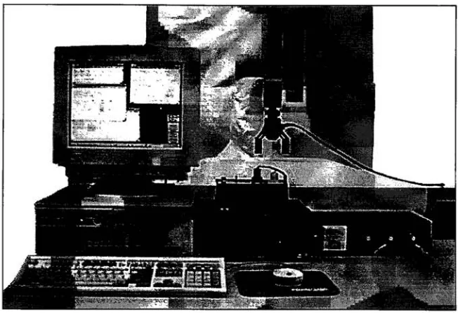
Figure 1
:
Controls Lab Station
with
TRI Gripper
Since
the
Controls
Lab
Station
is
capable
of
running
true
hardware-in-the-loop
simulations,
real-time
data
can
be
collected and
usedto
create
design improvements. In
this sense, the
system
allows
for
the
rapid-prototyping
ofcontroller
designs
for
the
Gripper.
However,
due
to this
rapid-prototyping
nature, the
Controls
Lab Station may
not
be
suitable
for
the
actual
implementation
of
the
proven
controller
design.
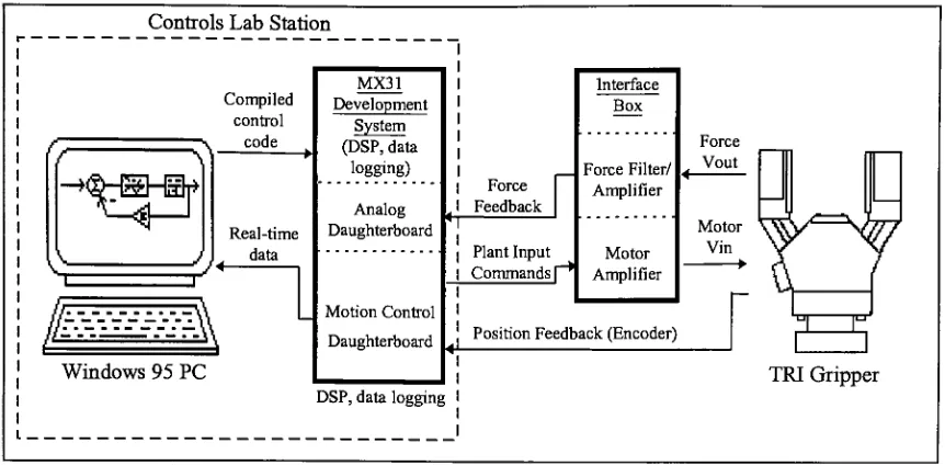
Controls Lab Station
^Hlr-irr>
Compiled
control v code
vi
?Real-time
data
Windows 95
PC
i
MX31
Development
System
(DSP,
data
logging)
Analog
Daughterboard
Motion
Control
Daughterboard
Force Feedback
Plant Input
Commands
[""*Interface Box
Force Filter/ Amplifier
Force Vout
Motor Amplifier
Motor Vin
Position
Feedback(Encoder)
DSP,
data
logging
r
i
[image:12.570.71.502.75.287.2]TRI
Gripper
Figure 2: Controls Lab Station Device Layout
One
ofthe
key
elementsin
rapid-prototyping
is
automatic
codegeneration
[2]. It
allows
the
userto
focus
on
controllerdesign,
without
having
to
be
concerned about
creating
the
algorithm which
implements it. This is especially
important
during
the
fine-luning
phaseof
controllerdesign,
wherethe
frequency
of
design iterations
tends to
increase.
The
automation of
the
code-generation
tasks
speeds
up
the
iteration
process,
and eliminates
the
chance
for
user
error.Software installed
onthe
Controls Lab Station PC
allows
exactly
this.
From
the
user's
graphical
block
diagram,
code
is automatically
created,
compiled,
and
downloaded
to the
MX31 Development System (see Figure 2). This is
accomplished
by
simply choosing
a
few
menu
items;
the
userneed not
be
knowledgeable
in
any
particularprogranrming
language.
A
second
important feature
of
a
rapid-prototyping
systemis
the
ability
to
log
and
analyze
data.
Essentially,
data
collectedduring
previous simulationsis
studied
in
orderto
facilitate
subsequent controller and/or
parameter revisions.This feature is
implemented
in
a
very
elegant
manner,
in
that
data
is
returnedin
the
same variablenames
called out
within
the
simulationblock diagram. In
otherwords,
collecteddata
is
readily
availablewithin
the
softwaredesign
environment,
withoutthe
needfor post-processing
orformatting
logged information.
Also,
this
enables macros or subroutinesto
be
set
up
to
perform
commonly
repeated
tasks
(i.e.,
graphing Time
vs.
Position,
etc.)
on
collecteddata.
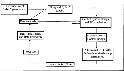
2.1 Design
Process
The
design
processitself
takes
on a cycle similarto that
shownin Figure 3 below. As
can
be
seen, the
design
process
follows
the
sameflow lines
regardless
ofthe
physical plant
being
used.This feature
means
that the
userneeds
to
become familiar
withthe
Lab
Station
equipmentonly
once,
andthen
use
it
for
various experiments without
the
needfor
re-training,
etc.Again,
this
permitsthe
userto
concentratemainly
onthe
design
aspects
of
the
cycle.
Determination
of"plant"
parameters.
Design
of "plant"model.
<
JData
Analysis.
[-Real-Time
Testing
and
Data
Collection.
A
Control
System Design
and
PC
simulation.Modifications
to
Control Design.
|
Download,
j
Add
specialI/O
blocks
for
hardware-in-the-loop
simulation.
Create Control Code
[<-Figure
3: Controls Lab Station
typical
design
cycle
Once
a planthas been
chosenfor study
and
aninitial
model
of
the
plant
dynamics
developed,
the
task
is
then to
design
a control
system whichgives
the
desired
plant
response.
Basically,
the
user creates aclosed-loop
controlsystem
around
the
plantmodel.
In
the
caseof
the
TRI
Gripper,
this control system can
be based
on either position
or
force
(grasping)
control.The
simulation
is
createdusing
the
various software packages
(MATLAB, SIMULINK,
etc.)
on
an
IBM-compatible PC.
Once
a
suitable
control
system
has been
built
(in
simulation
diagram
form in
SIMULINK),
automatic
code
generation
tools
are
used
(Real-Time
Workshop, RTLinkTM,
etc.)
to
transparently
translate the
simulation
diagram
into C
code.
This
code
is
then
automatically
compiled
using Texas
Instruments'
C31
compiler,
and
downloaded
to the
MX31
Development
System. The
userthen
chooses
when
to
start
and/or
stop
the
simulation.
When
the
[image:14.570.69.507.57.308.2]simulation
is
complete, any
stored
data is
automatically
uploaded
to the
PC.
MATLABcan
then
be
used
to
plot and analyze
the
data.
This
allowsthe
user
to
study
the
results of
the
current
controller
design,
and
make
adjustmentsif
necessary.The
updated
block
diagram
can
be
re-compiled,
and
the
process
begins
anew.3.0
Hardware
Although
comprised of
only
two
main
components, the
Controls Lab Station
representsthe
latest
in DSP-based
technology
for
control system
design
(see Figure 1). The
centraldevice is
the
MX31 Development
System
from
Integrated Motions Inc. This
unit containsthe
Texas
Instruments'C31 DSP
chip,
and other
motion controlhardware. The MX31
is
connected
to the
host PC
by
a standard
RS232
(serial)
cablethrough which
it
receivesthe
compiled control code.
These
two
components
together
define the Controls Lab Station.
Essentially,
any device
can
be
connected
to the
Controls Lab Station
transparently.
That
is,
the
userneed
not
makeany
changes
to
this
independent
systemin
orderto
accommodate a
specificdevice.
Ancillary
devices
are
then
attachedto the
MX31's I/O
ports
to
serve asthe
"plant"under
investigation
(see Figure 4).
In
this
instance,
the
device
being
driven
by
the
MX31
is
aTRI Corporation's EP 100/30 Servo End Effector. It interfaces
to the
MX31
via a custom
"Interface
Box"which
contains
a motor amplifier andforce
sensor signal amplifiers
andfilters. These
two elements, the
Gripper
and
Interface
Box,
together
will
be
considered
the
plant.
This
plantis mteresting in
that
it
providesthe
opportunity
to
develop,
simulate,
and analyze
both
positionand
force
control algorithms.Communications
between
the
Controls Lab Station
and
the
plantconsist of motor
drive
signals,
encoder
feedback,
and
force
sensor output signals.It
is important
to
again note
that the
Controls Lab Station
is
defined
as a
separateentity
from
the
plant
being
investigated.
However,
as
a
demonstration
of a complete
design
experiment, the
TRI
Gripper
and custom
interface
box
will also
be
discussed
here. The
following
subsections will
each
deal
with
the
details
ofone of
the
specific
hardware
components and
its
respective communications
flow.
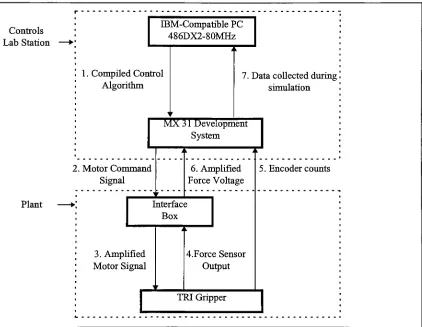
Controls
Lab
Station
IBM-Compatible PC
486DX2-80MHz
Plant
1
.Compiled Control
Algorithm
7. Data
collectedduring
!
simulationMX 3 1 Development
System
2. Motor
Command
Signal
6. Amplified
Force Voltage
Interface
Box
3. Amplified
Motor
Signal
4.Force Sensor
Output
5. Encoder
countsTRI Gripper
Figure
4: Controls Lab Station
and
Plant Interconnection.
Integrated
Simulation
andControl
of aServo-Driven
End Effector
[image:17.570.72.494.225.552.2]3.1
IBM-compatible
PC
Serving
as
the
user
interface
to the
Controls
Lab Station
is
an
IBM-compatible
486DX2-80 Mhz PC. It
is
equipped with
16 Megabytes
of
RAM
and a
720
Megabyte hard
drive.
The
current
operating
system
is
MicrosoftWindows
95.
Communications
withthe
MX31 Development System
are achieved
via a standardRS232
port.
The PC's RS232
(serial)
port
is
not
16550
UART-compatible;
this
limits
transmit
and
receiverates
to
9600
baud.
The
installation
ofsuch
a
serial
port
couldincrease
speeds
to
38000 baud.
However,
at
the
current
speed,
most
compiled models willdownload
to
the
MX3 1
in less
than
60
seconds.
Also,
onaverage,
2048
points of
collected real-timedata
will uploadback
to the
PC in less
than
30
seconds.
The PC
servesalso as
the
host
of
the
software
development
environment.
The
specifics
ofthe
software
packagesbeing
used will
be discussed later in Section 4.0
Software,
but
it is
important
to
mentionhere
that the
PC
providesthe
userinterface
to
allelements
ofthe
Controls Lab Station. For
example, the
main
development
environment, compiler,
MX3 1
build
parameters,
download
protocol,
and
instruction
setsfor
the
MX3 1
all reside on
the
PC.
3.2
MX31
Development
System
The
MX31
Developer's
System
provides
a
turn-key
solution
for
running
DSP
applications
such as signal
processing
and motion
control.The
systemis
equipped with
Integrated Simulation
andControl
of aServo-Driven End Effector
an
MX31 Motion Control
(MC)
daughterboard,
currently
used
to
interface
to the
TRI
Gripper
via
the
custom
Interface Box. The
outputlimits
ofthe
MC daughterboard
are
fixed
at
+/-10 Vdc
maximum.
An
additionalMX31
Analog
I/O daughterboard
(AIO
12/2)
adds another
2
inputs
and
2
outputs.
These
extra connectionsare utilized
by
the
force
sensors
installed
in
the
Gripper fingers. Inputs
to the
AIO
12/2
board
must
be
within
the
rangeof
+/-10Vdc.
Complete
specificationsfor
the
MX31
System
anddaughterboards
can
be found
in
Appendices A
and
B.
One
of
the
mostuseful
analysiscapabilities of
the
MX31
is
the
ability
to
log
real-timedata. While
the
setup
and analysis of collecteddata falls into
the
softwaredomain,
there
are
certain
system andhardware
considerations
worthy
of
notehere.
The
base MX31
system
contains64 Kilowords (128
KB)
of volatile
RAM. For
a
moderate sized
model,
16Kw
is
used
by
the
Real-Time
Workshopand
MX31
kernels,
kernel-dedicated memory,
and model code
[3]. This
leaves
no morethan
48 Kw
of
RAM
available
for data logging. As
anexample,
a
typical
modelmay be setup
to
log
time
(T)
and
three
outputs
(Y),
using four 12 Kw buffers. With
a
standardsample
time
of
1
msec,
this
meansthat
12.287
secondsof
data
could
be
stored.
The
mimmumsample
time
is
largely
dependent
on
the
complexity
and size of
the
model.
However,
if
a model employs
the
AIO
12/2
(Analog
I/O
daughterboard),
sample
time
can
Integrated
Simulation
andControl
of aServo-Driven End Effector
be
noless
than
.2msec.
In
the
case
ofa
larger
model,
expectsample
times to
be
noshorter
than
1
msec.
3.3 TRI Gripper
A
servo-controlled end effector equipped
withfinger-mounted
force
sensors provides
anideal
plant
for
the
userto control,
as
both force
and
position control canbe implemented.
In
this case,
aTRI
Corp. EP 100/30 Gripper is
utilized.Vendor
specifications are given
in
[image:20.571.198.375.317.530.2]Appendix C. Figure 5 below
shows
apicture
ofthe
EP
100/30.
Figure 5: TRI EP 100/30 Servo-controlled
Gripper
The
Gripper
is
equipped with a non-backdriveable screw
drive
transmission,
so
finger
position
is
maintained withoutan applied motor
input
voltage.For
position
encoding,
a
Hewlett-Packard
HEDS-9100
optical
incremental
encoder
is
utilized
which
is
self-contained
withinthe
TRI Gripper
main
body.
The
encoder
uses astandard
two
channel
Integrated
Simulation
andControl
of aServo-Driven
End Effector
quadrature
output
to
detect
the
rotary
motion
of
the
screw
drive. Resolution
of
the
encoder
is dependent
upon
the type
of
codewheelused;
the
suppliedHEDS-5120
codewheel
has
a resolution of
512 Counts/Revolution. The 5Vdc
power
requirementsof
the
encoder are supplied
by
the
MX31's
Analog
I/O daughterboard (see Appendix B for
wiring
details).
Complete
encoder specifications are
givenin
Appendix
D.
Force sensing
is
accomplished via
the
use of ananalog force
sensorin
each
finger. The
force
sensor output
is
approximately
+/-125
mVdc/Vdcof supplied voltage.
Since
a
+/-10 Vdc
power
supply
is
used
for
the
force
sensors,
actual output voltage
is
approximately
+/-
1.25 Vdc
at
full
scale
for
each
sensor.This
voltageis
obtained
withan
appliedmaximum
load
of60 lbs
persensor,
as per
the
vendor'sspecifications.
An
independent
supply
was usedfor
the
force
sensors
in
an
attemptto
minimize
noiseeffects
from
the
main
motor powersupply.
3.4 Interface Box
An interface box
was
designed
and
built
to
provide
a
seamless,
hassle-free
means
of
connecting
the
TRI Gripper
to the
MX3 1 Development System. It
provides
three
main
functions:
amplification of
the
Gripper
motor
input
signal,
filtering/amplification
of
the
Gripper force
sensor
outputs,
and
a
manual
Gripper drive. Each
function
will
be
discussed
in
detail in
the
following
subsections,
and a complete
wiring
diagram
of
this
subsystem
is
given
in
Appendix E.
Integrated
Simulation
andControl
ofaServo-Driven End Effector
3.4.1 Motor Amplifier
A
motor amplifier
is
required
to
step up
the
voltage outputof
the
MX3 1
in
order
to
match
the
drive
requirements of
the
Gripper
motors.
The TRI Gripper
requires voltage
in
the
range of
+/-12-48
Vdc,
while
the
MX31 MC daughterboard
canonly supply
a range of
+/-0-10 Vdc.
An
Advanced
Motion
Controls'(AMC)
Model
5A5
amplifierand
MC1X510
mounting
card were chosen
because
oflow
price,
small
footprint,
easeof
setup
and
low
power
requirements.
See Appendix F
for
specificationsand
setup
directions
for
this
device. It
is designed
to
drive brush
type
DC
motors,
and
for
this
application
is
setup
to
runin
voltage mode.
In
this mode, the
output voltage
follows
the
input
voltage.
Pot
3
onthe
amp
card
(See Appendix
F)
sets
the
current
limit;
this
has been
adjusted
to
limit
motorinput
current
to
3.5
amps as per
TRI's
specifications.
Pots 1
and
2
can
be
adjustedto
set
the
reference offset and
gain,
respectively.3.4.2 Force Sensor Signal Filter / Amplifier
A
simplefilter/amplifier
wascreated
in
order
to
step up
the
output voltage of
the
Gripper
force
sensors.This
acts
to
add resolution
to the
signal since
the
full
range of
the
sensor
output now almost matches
the
limits
of
the
MX31
Analog
daughterboard's inputs.
Since
the
Gripper
usestwo
independent force
sensors, two
separate
amplifier circuits were
built.
Shown
in
Appendix E
is
the
wiring
diagram
of
the
device.
Integrated Simulation
andControl
of aServo-Driven End Effector
The
main
component
of
the
filter/amplifier
circuitry
is
a
Burr-Brown
INA114
Instrumentation
Amplifier
8-pin DIP
chip.
This device
was chosenbased
on a
numberof
factors,
the
major ones
being
low
cost,
excellentaccuracy,
largely
variable
gain,
and
small power requirements.
Specifications
for
this
componentare
listed
in Appendix
G.
The
circuit
is
mounted
ona
breadboard
inside
ofthe
Interface Box. The 10KQ
trim
potshave
eachbeen
setto
8
KQ,
yielding
again
of7.25 for
eachof
the
INA114
chips.
Therefore,
withfull load
output of
the
force
sensors
at1
.25Vdc,
the
MX3 1
Analog
daughterboard
will see an amplified voltage of
9.0625 Vdc.
By
using
the
entire range
ofthe
Analog
daughterboard's
input
voltage(+/-
lOVdc),
it is
possible
to
gain
the
highest
possible
precisionin force
sensor
load detection.
3.4.3 Manual Gripper Drive
Since
the
MX31
is
a
rapid-prototyping
system,
wherea single model
is
run and
then
removed
from
the
volatile
memory, the
Gripper
fingers
cansometimes
be
left in
an
undesired
position whenthe
model
terminates.
Or,
mistakes
in
the
model parameters can
cause undesired results.
Thus,
it
was
necessary
to
provide
a manual
override
for
the
Gripper.
The
manual
Gripper drive
was
realized
by
using
three
electrical switches.
The
first,
an
SPST
type switch,
simply
cuts
high
power
to the
AMC
5A5
motoramplifier.
This
acts as
an
Emergency-Stop
to
immediately
halt
Gripper
finger
motion
in
case of an accident or
Integrated
Simulation
andControl
of aServo-Driven
End Effector
undesired
operation
due
to
model error.
The
secondswitch,
another
SPST
type,
allowsthe
user
to
select
between
"computer"or
"manual"
control.
Gripper
motion caused
by
the
MX31
is
enabled with
the
switch
in
"computer"
mode.
In
"manual"
mode, the
MX31
is
prevented
from
driving
the
Gripper,
and control
is
passedto the third
switch.
This
last
switch,
a
DPST
momentary-contact
type,
has
no
effect whenin
"computer"
mode.
However,
when
in
"manual"
mode, the
switch can
be
usedto
drive
the
Gripper
fingers
slowly in
either
direction
when
it
is
thrown
from
its
center-off position.Essentially,
a
minimal
voltage(+/-
lOVdc)
is
applied
to the
Gripper
motor.Holding
the
switch
in
oneposition
will openthe
Gripper
fingers;
holding
it in
the
other
positionreverses voltage
polarity
and
thus
causes
the
Gripper fingers
to
close.This
"manual"
mode
feature
allows
the
userto
ready
the
Gripper
for
another
trial
of anewly
downloaded
model.
For
example,
if
testing
a simplegrasping
model, the
user willwant
to
have
the
fingers in
a
common open
positionbefore
each run.
Integrated
Simulation
andControl
of aServo-Driven
End
Effector
4.0 Software
The
software of
the
Controls
Lab Station
not
only
providesa user
interface for
creating
a
control
system,
but
also performs
the
compilationand
downloading
of
the
controlcode.
This
software which allows
the
Controls Lab Station
to
function
as an
integrated
system
is
a mix of standard purchased software
packages,
as wellas
customMATLAB
files,
SIMULINK
libraries,
and utilities.
Each
will
be discussed
below,
with
an emphasis onthe
custom
softwaredeveloped for
this
application.4.1
Standard Software
:
MATLAB Environment
The
Mathworks'MATLAB,
SIMULINK,
and
Real-Time
Workshop[4-6]
provide
the
foundation for
the
Controls Lab
Station
software environment.These
packages
worktogether
with softwarefor
the
LMI
MX3 1
to
givethe
user
accessto the
necessary
tools
for
creating
and
analyzing
controlalgorithms
for any
given
plant.The
MATLABpackage
is
a powerfulsoftware
applicationdeveloped
initially
for
matrix
manipulation.
It
is
an
interactive
system whosebasic data
element
is
a matrix which
does
not require
dimensioning.
MATLAB
has
been
used
for
general numerical
computation,
applied
linear
algebra,
and
algorithmprototyping
as
wellas
problem
solving for
automatic control
theory
anddigital
signal processing.
MATLABalso
has
an
inherent
upgrade
capability
in
the
form
of application-specific
toolboxes.
Toolboxes
consist of
collections
of
MATLAB
functions,
which
are
invoked
transparently
to
expand
Integrated Simulation
andControl
of aServo-Driven End Effector
MATLAB's
capabilties.
The
toolboxes
which are
usedby
the
Controls
Lab Station
will
be
discussed in
the
following
paragraphs.
4.1.1
MATLABToolbox
:
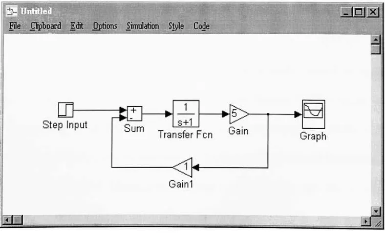
SIMULINKSTMULINK
is
a
dynamic
system
simulation
package whichextends
MATLAB's
capabilities
by
using
a graphical
"drag
&
drop"type
interface
to
createblock diagrams.
A
simulationmodel can
be
created
by
simply choosing
the
appropriate
function
blocks,
and
interconnecting
the
blocks
withdirectional flow
arrows.Inputs
to the
simulation can
come
from
the
MATLABworkspace
(as
matrices),
and
simulatedoutputs
can
be
displayed
as
graphs
or
stored
in
MATLAB variables.This
method
is
the
basis for
creating
and
simulating
control
systems,
priorto
implementation
on real world
hardware.
-
nixi
File
Clipboard
ErBt
Options
irarJation
Style
Code
Step
Input
Sum
8+1Transfer Fen
Gain
Gain
\*
[image:26.571.97.473.412.644.2]Graph
Figure 6:
Sample
SIMULINK
Block
Diagram
Integrated
Simulation
andControl
of aServo-Driven End Effector
4.1.2
MATLABToolbox
:
Signal
Processing
and
Control
Systems
The
Signal
Processing
and
Control Systems
toolboxes
add
functionality
required
during
the
design
and
analysis
of
block
diagrams
for
plant control.The
Signal
Processing
toolbox
adds
functions for digital
filters,
time-series analysis,
and
FFT
analysis.
The
Control Systems
toolbox
includes
functions for
controlengineering
and systemstheory.
These
toolboxes
appear
asadditional
block libraries in SEVIULINK.
Any
individual
block
canbe
usedin
a givenmodel
simply
by
dragging
anddropping
it from
the
library
to the
current model.
4.1.3
MATLABToolbox
:MX31
SIMULINKLibrary
Included
asa
part ofthe
IMI Developer's System
package, the
MX31
SIMULINKLibrary
containsa set of
device driver blocks built specifically
to
communicate
to the
MX31.
These
blocks
represent
the
link between
the
MX31
hardware
and
the
SIMULINK
graphical model.
This
allows
the
user a symbolic method of
controlling
data flow
to
and
from
the
MX31. The
Analog
I/O
and
Motion Control
daughterboards
each
have
an
independent
subset offunction blocks. Specific
examples of
the
use of
the
blocks
withinthis
library
willbe discussed in Section 6.0 Results
and
Demonstrations.
For
reference, the
MX31
SIMULINK
Library
is
contained
in
the
file
MX31LIB.M
within
the C
:\MATLAB\TOOLBOX\CODEGEN
subdirectory.
Integrated Simulation
andControl
of aServo-Driven End Effector
4.1.4
MATLABAdd-on
:
Real-Time
WorkshopThe Real-Time
Workshopcan
be
run
directly
from
SIMULINK,
and
allowsthe
userto
compile
the
current
block
diagram
using
an
external compiler.In
this way,
a
sampleblock
diagram
can
be
compiled
and
downloaded
to
use
in
an
embedded controlapplication.
The Real-Time
Workshopessentially
providesa
link
between
the
compilerand
SIMULINK,
without
the
need
to
exit
the
MATLABenvironment.4.1.5
RTLINK/ MX31 C Libraries
RTLINK
and
the
MX31
C
Libraries
workin
conjunction withthe
Real-Time
Workshop
to
create code which will run
specifically
on
the
MX31 Development
System. At
this point,
RTLINKis
still "beta"
software,
meaning it
is
still
in
the
testing
phase,
andall
features
are
not
yetsupported.
RTLINK worksin
the
background,
simply modifying
the
functionality
of
the
Real-Time Workshop. While
the
Real-Time
Workshop
interfaces
SIMULrNKto the compiler,
RTLINKessentially
customizes
the
actions ofthe
Real-Time
Workshopto
usethe
MX31
Library
routines and create
code
specifically for
the
MX3 1
.Integrated
Simulation
andControl
of aServo-Driven End Effector
,JOlx|
_
Integration
Options
Algorithm:
^Ntme
Step
Size:
Data
Logging
Options
P
Time
ft)
H
Scopes
ates
(X)
T
Outputs
(YJ
Output File:
File
Format:
Template
Makefile:
mx31_pc.tmfTarget Makefile:
j$model.mk
Build Command:
[image:29.571.165.406.54.378.2][make
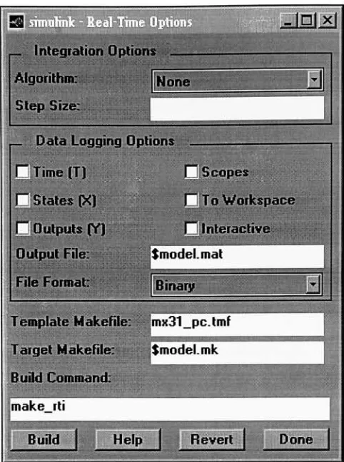
rtiFigure 7:
RTLINKCode Generation
Options
The
main
RTLINK screen(see Figure
7)
appears whenthe
Real-Time
Workshopis
invoked from any
SIMULINK model window.This
presents
the
user
with
several
choices,
such
asthe type
of
discrete-time
algorithms
to use,
as
well
as
data
logging
parameters.
Since
the
current release ofRTLINKis
still
in
the
beta
testing
phase,
only
Time(T)
and
To
Workspace
variables
can
be
chosen
for
data
logging.
Future
revisions
of
RTLINKwill
enablethe
other options plus additional
features.
Integrated
Simulation
andControl
of aServo-Driven End Effector
4.1.6 Texas
Instruments'C31 Compiler
The
compiler required
to
create code
for
the
MX31 is Texas
Instruments'C31
compiler.
This
valuable
tool
resides on
the
host
PC independent
of
the
Controls
Lab Station
design
environment
(MATLAB,
etc.)
and
is
a
fully
functional
complete versionof
a
C
compiler.
However,
several
MATLABinitialization
files
were
modifiedin
order
for
this
compiler
to
become
the
default
when
creating
code
using
RTLINK(see Section 4.2.1
Custom
MATLABFiles
below). It
should
be
notedthat
Texas
Instruments graciously
provided
the
C31 Compiler free
of charge as an educational
tool.
4.2 Custom
Software
Several
piecesof customized
software
were createdin
orderto
tightly
integrate
the
standard
software packagesdiscussed
above.
This
results
in
a
user-friendly
environment,
where
the
user can concentrate effortson
the
design
experiment,
without
the
need
to
develop
extensivecode
for
a given application.
In
addition,
acustom
SIMULINKTRI
Library
was created
by
the
authorin
order
to
simplify
the
use of
the
TRI
Gripper. Since
this
planthas
such
widespreaduses
and
educational
value, this
library
was
built
to
provide
users
withcommonly
usedtools
in
asimple
drag-and-drop
style
library.
Integrated Simulation
andControl
of aServo-Driven End Effector
4.2.1 Custom
MATLABFiles
In
order
to
create a
user-friendly
design
environmentfor
the
Controls Lab
Station,
severalMATLAB
standard
initialization files
were
slightly
modified.By doing
so, the
out-of-the-box
MATLABsoftware
package
became better
suitedto
actas
the
design
environment
for
the
Controls
Lab
Station.
Although
the
basic
functionality
and
feel
of
MATLAB
was
retained, the
customization
enableda
design
environmentfocused
around simulation and
development
for
the
IMI MX31 Developer's System.
The
custom
files
perform actions
necessary
to
integrate
the
many
software
components,
as
well as setup
pointers andvariables
necessary for
codegeneration
for
the
MX3 1
.Two
main
files
are
involved
in
this
custominitialization:
STARTUP. M
and
MATLABRC.M.
The
first
of
these
files informs
MATLABto
use
RTLINKwhen
compiling,
while
the
latter loads
the
custom
IMI
Control Panel
and
TRI
Gripper
libraries.
Also,
a
default
model sample
time
of.001 secis
set
up in
the
variable
Ts.
Both
ofthese
files
exist
in
the
C
:\MATLAB\
subdirectory.For
reference,
alisting
of
these
files
is included in Appendix
H. It
is
suggested
that
backup
copies
of
these
files be
maintained,
especially before
attempting any
modifications.
4.2.2 IMI
Control Panel
The
IMI
Control
Panel
was created
in
order
to
group
several
commonly
used
commands
together
in
a graphical
interface.
This
gives
the
user quicker access
to
commands needed
Integrated
Simulation
andControl
of aServo-Driven End
Effector
when
using
the
Controls
Lab
Station.
The
windowwas
created
using
standardMATLAB
script
syntax,
and
the
file is
storedas
IMI.M
in
the
C:\MATLAB\
subdirectory
on
the
host
PC. A
listing
of
this
scriptis
given
in Appendix
I.
File
Edit
Windows
Help
'Remote
Control'Demos...
H E LP!
About
TRI
Library
MX31
Library
MX31
monitor
Simulink
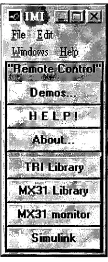
Figure
8: Custom Control Panel
The
DVII Control Panel
popsup automatically
when
MATLABis
started on
the
host
PC. Figure 8
above shows
the
available
commands which can
be
invoked
simply
by
clicking
the
appropriate pushbutton.As
canbe
seen
from
Figure
8,
options range
from
online
help
and
demos
to
commands
andfunctions
for
the
MX3 1
and
the
TRI
Gripper.
It
shouldbe
notedthat
any
commands
listed
on
the
Control Panel
can also
be
invoked
by
giving
the
appropriatecommand at
the
MATLABprompt.
However,
in
keeping
with
the
Integrated
Simulation
andControl
of aServo-Driven End Effector
[image:32.570.229.341.166.437.2]goal of a
user-friendly environment,
an
organized point-and-clickinterface
was
deemed
to
be
more
desirable.
If
additional
functionality
is
needed, the
contents
ofthe
Control
Panel
window can
be
modified
simply
by
editing
the
scriptcontained
withinthe
file
IMI.M.
4.2.3 Online
Help
As
an additional
feature
to
help
new users avoid
commonmistakes, the
Controls Lab
Station
is
equipped with online
help
files.
By
clicking
on
the
appropriate
button
on
the
IMI
Control Panel (see Figure
8),
aDOS
window
opens anddisplays helpful information.
The
HELP!
button
will
display
data
in
a
familar
question-and-answertype
format. The
About.
..button displays
important
background information
aboutthe
Controls Lab
Station,
as well as
a"quick
start"guide
to
creating
controlalgorithms
in
SIMULINK.
When
finished,
the
DOS
window closes
automatically
and
the
useris
returned
to the
MATLAB
design
environment.This
is
convenient
in
that
the
userdoes
not need
to
save
data
and
exitMATLABin
order
to
gain
accessto the
help
files.
By
having
basic helpful
tips
availablefrom
withinMATLAB,
the
user canlearn
more
quickly
and
create
working
controlalgorithms
in
a shorter
period of
time.
The
help
files
are
simpleDOS
text
files
contained within
the C
:\MATLAB\
subdirectory.
The
file
namesare
IMIHELP
.M
and
IMIABOUT
.M.
Complete listings
of
these two
files
have been
placedin
Appendix J
as
a
reference.
Also,
see
the
MATLABscript
in
Appendix I for details
on
how
the
files
are
invoked from
the
Control Panel.
Integrated
Simulation
andControl
of aServo-Driven End Effector
4.2.4 TRI
Library
The TRI
Library
is
a set of custom
SIMULINKblocks
that
provide
unit conversion
utilities
for
use with
the
TRI Gripper
plant.
Two
mainfunctions
can
be
performed:1)
convert encoder counts
to
inches,
and
2)
convert
force
sensor
voltageto
average
grasping
force. Shown in Figure 9 below is
the
library
as
it
appears
when calledfrom
the
Control
Panel.
?jxj
File
Clipboard
Edit
Option;
Simulation
Style
Co/Je
These blocks
convertEncoder Counts
to
Inches
ofopening for
the
TRI Gripper.
=0
T3
Counts
>lnches
Inches>Counts
For
the
detailed
relationships usedto
createthese
blocks,
seetrilib2.rn
These blocks
convertforce
sensor voltageto
Lbf Measurements.
0
Volts->Force
Left Sensor
>%>
Volts->
Avg. Gripper Force
pg
Volts->Force
Right Sensor
[image:34.571.113.460.304.585.2]Created 9/27/96
by
Thomas LeBlanc
Figure 9: TRI
Library
Integrated
Simulation
andControl
of aServo-Driven
End
Effector
The
purpose of
this
library
is
to
allow
the
userto
use convenient units while
creating
controllers
for
the
TRI
Gripper
plant.
For
example,
ratherthan
attempting
to
use encoder
counts as
the
feedback in
a position control
experiment, the
Counts>
Inches block
can
be
used
to
convert
the
values
into
actual
inches
of
opening
ofthe
Gripper
fingers.
The
blocks
can
be
used
in
any
SDVIULINKmodel,
and
are
simply
a
1
-input,1
-outputstyle.
Essentially,
amathematical
function
is
applied
to the
input
port and
sentthru the
outputport.
Section 5.0 Plant Integration
will
describe in detail how
the
blocks
were created
for
the
TRI
Gripper
plant.
Also,
the
related
file
names willbe
provided as a reference.
It
should
be
noted
that the
TRI
Library
is intended
to
be
used
only
when
the
TRI
Gripper
and
Interface Box
is
the
plant
being
investigated.
The
equations used
to
perform
the
conversions
are
only
valid
for
the
geometry
and
sensor characteristics of
the
TRI EP
100/30
Gripper,
when used
withthe
Interface Box. The TRI
Library
was created
to
not
only
provide convenient utilities
for
the
Gripper
plant,
but
alsoto
serve as an example of
how
this type
of
utility
canbe
implemented.
If
another plant
is
to
be
used, this
library
will,
at
the
very
least,
need
to
be
modified.
Since
allblocks in
the
TRI
Library
were
created
using SIMULINK's
maskfunction,
the
user canchoose
to
unmask
any
ofthe
blocks
to
see
the
underlying
equations.
Any
modifications should
be
made on a
copy
of
the
TRI
Library,
not
the
original
itself.
Integrated
Simulation
andControl
of aServo-Driven End Effector
5.0
Plant Integration
In
order
to
seamlessly
interface
the
TRI
Gripper
plantto
the
Controls Lab
Station,
severalother software
issues
were
taken
into
consideration.These include further
filtering
ofthe
force
signal
through software,
force
sensor
calibration,
and conversionutilities
for
the
force
sensors and
Gripper
encoders.
The
result
is
a
set ofSIMULINK
blocks
whichcan
be
used
in
a
systemmodel
to
greatly
enhance
any
controlalgorithm
for
the
TRI Gripper
plant.
It
should
be
notedthat these
software
tools
and proceduresare
dedicated
to the
TRI
Gripper;
the
use of another plantmay
require
similardevelopment in
order
to
integrateit
with
the
system.Also,
due
to the
very
nature
ofthe
MX31,
the
Controls
Lab
Station is
intended
to
be
used as
adevelopment
and analysis
tool
for
the
design
of control systems
for
real-worldhardware. The
authordoes
not
recommendusing
the
Controls
Lab Station
with
the
TRI Gripper in
a
fully-automated
robotic
application.5.1 Software Force Sensor
Filtering
During
preliminary
testing
ofthe
Force
Sensor
inputs
to the
MX31,
it
was
discovered
that
noise was still apparent
in
the
force
signal
despite
the
filtering
done
at
the
Interface
Box.
This
was
determined
to
be
causedby
the
close physical
proximity
of
the
PC, MX31,
Interface
Box,
and
DC
powersupplies.
Thus,
it
was
necessary
to
further filter
the
force
Integrated Simulation
andControl
of aServo-Driven
End
Effector
signal
to
eliminate noise.
This
was
accomplishedby
using
a
SIMULINKFilter
block,
specifically
a
Low-Pass Butterworth
Filter.
A
second-order
Low-Pass Butterworth Filter
was
chosendue
to
its
flat
responseand
minimal phase
shift
(time
delay)
at
low frequencies.
Also,
sincethe
filter is entirely
software
(i.e.,
filtering
occurs at
runtime),
it
is
more
precisethan
a
hard-wired
filter,
and
there
will no
opportunity for
noiseto
re-enterthe
signal.This
allows us
to
effectively
filter
out
the
signal with anessentially
transparent
"device."That
is,
no
further
degradation
of
the
force
signalshould occur
through this
filtering
process.Although
the
SIMULINKlibraries
contain
a ready-to-useButterworth Filter
block,
the
derivation
willbe
presentedhere
as an exercise.
Using
a standard
Butterworth
form
[7],
a
second-order
low-pass
filter has
a
transfer
function
representedby:
H(ja>)
=(Eqnl)
!-(/
J2+j(V2)(a>/a)J
w