PARAMETRIC PLASTIC COLLAPSE LOADS
AND THEIR VALIDATION FOR
HORIZONTAL SADDLE SUPPORTED STORAGE VESSELS
D H Nash and J Spence
Department of Mechanical Engineering, University of Strathclyde, 75 Montrose Street, Glasgow G1 1XJ
ABSTRACT
Recent work by the present authors on the collapse conditions for horizontal cylindrical saddle supported storage vessels is described and reviewed. Attention is directed to a range of geometries, typically R/t < 200, where plastic collapse type failure may be relevant. A series of forty tests on end-supported model cylinders loaded centrally by a rigid saddle were performed and a variety of theoretical methods were used for comparison with the test results. It was found that the best agreement was obtained by using an elastic-plastic finite element analysis approach. The results of a parametric survey based on the elastic-elastic-plastic finite element method are summarised. The paper reports some validation checks, which have been performed to support the parametric results.
NOTATION
A Longitudinal distance to the saddle support centre line from the end of the cylindrical shell (mm)
b1 Width of saddle (mm)
L Barrel length of the vessel (mm)
LS Longitudinal distance between saddle supports (mm)
R Mean radius of vessel (mm)
t Shell thickness of vessel (mm)
y Tensile yield strength of shell material (N/mm2) 2 Saddle embracing angle (degrees or radians)
P Parametric collapse load by elastic-plastic analysis (kN)
Pex Experimental collapse load (kN)
Pmin Upper bound limit load by limit analysis (kN)
Pinc Inscribed yield solution by limit analysis (kN)
Pkrup Krupka's simplified solution by limit analysis (kN)
Plb Lower bound limit load by elastic compensation method (kN)
1. INTRODUCTION
Horizontal vessels are widely used as storage vessels for liquids or gaseous products. Such vessels are commonly supported above ground by twin saddles, Fig. 1a. The saddles may be either fitted loosely or welded to the vessel. Current design rules tend to limit the maximum stress in the saddle region to a particular value or to employ a Design-by-Analysis approach. The two approaches differ little in the final design. However, in the absence of a fatigue requirement it may be appropriate to base the design of the vessel on the plastic collapse load of the vessel. In this way the designer can find an allowable load directly from the collapse load by dividing by an appropriate factor, usually 1.5. This has the merit of avoiding the calculation or the categorisation of the stresses.
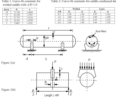
Plastic collapse loads have been investigated by the authors [1,2,3] and by Krpka [4,5,6,7,8] in a range of simple experimental tests on end supported steel cylinders loaded centrally by an external saddle load, Fig 1b. It was found that there are two main modes of collapse, a gradual plastic collapse and a more sudden elastic-plastic buckling failure. Plastic collapse occurs when the vessel radius to shell thickness is relatively small [typically R/t < 200] and is characterised by the sequential formation of plastic hinges which cause the eventual collapse of the vessel.
A typical cylindrical vessel is shown in Fig. 1a and assumed to be fluid filled as this represents the worst loading case. The vessel is unstiffened and has two saddle supports each with a saddle reaction force of P. If a portion of the vessel is isolated and inverted it can be considered to be loaded through one saddle with force P as in Fig. 1b. The force P can be treated as an applied force which represents the specific weights of the liquid and vessel material. The ends of the model were supported on saddles. This represents a convenient test arrangement. However this approach assumes the saddle effect is a local problem. Thus the model test results may not be fully representative of real vessel behaviour.
The work reported here is essentially based on the work of the late Professor A.S. Tooth and his researchers, particularly Moses Chan, at the University of Strathclyde.
2. EXPERIMENTAL RESULTS
The results of a programme of 40 experimental results on steel vessels using this inverted configuration, including both welded and loose saddles are reported in [1]. The models covered a range of R/t ratios from 62 to 455 and length to radius ratio of c4.2. These were brought together with other similar experimental results to give a total experimental base for comparison of 70 tests. The collapse load is simply the highest load sustained in the test.
The formation of plastic hinges is different for saddles which are welded to the vessel than for those where the vessel is placed loosely on the saddle. In the case of welded saddles the hinges occur at the horns and [usually] on one side of the nadir close to the saddle. Loose saddles, on the other hand, have symmetric hinges which form round the periphery of the saddle/vessel interface; this ultimately results in a localised indentation on the shell surface under the saddle, referred to, by Krpka, as a ‘foot print’ [8]
3. THEORETICAL ANALYSES
The following methods of analyses were used [3] to give estimates of the collapse loads for both welded and loose saddles.
a) Rigorous upper bound analysis [9].
b) As above, with an inscribed yield surface [9]. c) A simplified upper bound solution [5,6].
d) An elastic compensation method, lower bound [10,11]. e) An elastic compensation method, upper bound [10,11]. f) An elastic-plastic finite element method.
A comparison of the six approaches above indicates that the elastic-plastic finite element method gave the best comparison with the experiments on the model tests. The finite element approach was thereafter used to explore the effect of various geometric parameters and subsequently to conduct a full parametric study on realistic geometry configurations appropriate to ‘real’ vessels rather than the test models.
4. COMPARISON OF THEORY AND EXPERIMENT
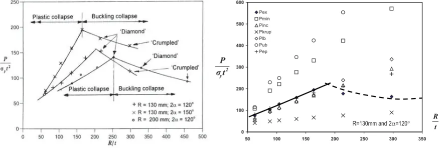
Typical results for welded saddles are shown in Fig. 3 for comparison with one of the data sets in Fig. 2. All of the theoretical results are shown. Although the theoretical values are valid only for plastic collapse, results have been included throughout the whole range of R/t for completeness. This serves to emphasise the transition in the buckling behaviour. Some of the comparisons are disappointing although individual theoretical approaches may be useful in some cases. For example, the simplified upper bound solution from Krpka [5,6] gives good agreement with the tests on loose saddles, but not for welded saddles. Further details are given in [3]. The main observation is that the elastic-plastic finite element collapse load gives the best approximation to the experimental results. Subsequently, it was decided to use this method to conduct a parametric survey on actual vessel configurations. Essentially the above work assumes that collapse is a local phenomenon and a model length of approximately 4R is sufficient to avoid interaction effects from the ends of the model [3]. While these results are useful for comparisons between theory and experiment, the values need to be treated with care when considering actual vessels.
5. PARAMETRIC STUDY
It will be appreciated that all of the above theoretical results are restricted since they either treat the saddle-supported problem as a local problem (the first three cases), or they have been configured to suit the experimental set-up. In order to conduct a parametric survey which is appropriate to actual vessels, it is necessary to include all of the factors which influence the collapse of horizontal vessels supported on twin saddle supports and, of course, to modify the finite element model: these include,
(a) the fixture of the saddle and vessel, i.e. welded or loose (b) saddle embracing angle (2)
(c) saddle width (b1)
(d) total length of the vessel (L)
(e) distance of the saddle centre profile from the vessel "head" (A)
Preliminary work established that the length L=4R was not adequate for assessing the load on actual vessels i.e. of L>>4R. For longer lengths of cylinder, the collapse load could be substantially lower than those of the model tests especially for welded saddles [13]. Based on some limited finite element studies, Krpka [12] has also noted that the length, specifically the distance of the saddle from the stiffened end, is of greater importance for the limit carrying capacity on welded saddles than for loose saddles.
symmetrical FE model used to evaluate the experiments. The welded cases were approximately two thirds those found previously although the loose saddle results were not much different. Thus the model experiments, while useful as a database of tests, should not be considered representative of collapse or buckling loads for actual vessels of corresponding geometric dimensions especially for welded saddles. Vessels of A/R ratio equal to 0.5, 1.0, 2.0 and 6.0 and values of R/b1 (where is in radians) of 2.0, 3.5, 5.0, 7.5 and 10.0 were examined. Various vessel radii of 130mm, 500mm, 1000mm and 4000mm were used. The saddle location was restricted to the quarter point on the vessel but with the vessel's total length varying from 2R, 4R, 8R and 24R (representing A/R of 0.5, 1.0, 2.0 and 6.0). The saddle-embracing angle was restricted to between 120 and 150. The saddle width, saddle embracing angle and the vessel's radius were varied to include a range of values of the ratio R/b1 namely 2, 3.5, 5.0, 7.5 and 10.0. The thickness of the vessels was such that the R/t ratio does not exceed 300 to adequately ensure the cases correspond to plastic collapse. The material property of the shell is assumed to be elastic-perfectly plastic with a yield strength of 300N/mm2. A total of 105 vessels with welded saddles and 113 vessels with loose saddles were analysed to determine the various collapse loads. All of the results are detailed in [13].
Fig. 4 shows some typical results for a welded saddle for a fixed value A/R = 1.0. There is a slight scatter in the results due to the combined geometrical parameter involving b1/R and R/t. Results for loose saddles are generally similar but tend to be slightly lower for a given geometry. All the results for other values of A/R
are given in [13]. The collapse loads reduce as A/R increases so that when A/R = 6 the values are approximately 1/3 of those shown in Fig. 4.
From the point of view of application in design situations, it may be useful to have the parametric results in a more directly useable form. Accordingly the best fit curves for all of the data, have been characterised in terms of a simple power law of the form,
n y b R K t P ¸¸¹ · ¨¨© § 1 1 2 D
V [5.1]
Values of K1 and n are given in Table 1 for the welded saddle cases for A/R = 1.0. Values for other A/R
ratios are given in [13]. It is in fact possible to further condense the parametric collapse load results by increasing the combination of geometric parameters, albeit this results in some additional scatter. The results are shown in Figures 5 and 6 for typical welded and loose saddle cases against the grouped parameter
¸¸¹ · ¨¨© § 1 1 b R Rt
b D . This has the merit of allowing all the results to be shown neatly on one graph. Again these may
be fitted with a simple power law of the form,
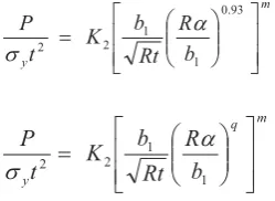
m y b R Rt b K t P » » ¼ º « « ¬ ª ¸¸¹ · ¨¨© § 0.93
1 1 2 2
D
V 5.2]
for the welded case and
m q y b R Rt b K t P » » ¼ º « « ¬ ª ¸¸¹ · ¨¨© § 1 1 2 2 D
V [5.3]
for the loose saddle case. The values of K2 and m are given in Table 2 for both the welded and loose saddle cases (with the values of q identified in Fig. 6 for the loose case).
VALIDATION
boundary conditions [1] where there was a degree of radial restraint imposed by thin rings inserted into the open ends of the test cylinder. The analyses in d) e) and f) above were conducted using ANSYS [14]. As the original finite element work was conducted about 9 years ago, and the original investigators are not available for consultation, it was decided to undertake some simple validation runs. Fortunately the plastic collapse condition is relatively insensitive to the total number of elements or even the boundary conditions remote from the saddle. When the original calculations were repeated, slightly lower collapse loads were obtained when using the same finite element model, albeit with a more recent version of ANSYS. The differences were not considered to be significant. Changing the end boundary conditions to radial restraints, which seem appropriate to the experimental arrangement, gave virtually identical results. However, it should be understood that these conditions relate to a relatively stiff end. Similar results were obtained for the modified finite element model employed for the parameter study. Typical disparities were of the order of 5% which seems acceptable considering the approximations and the scatter associated with the reduction of the data in order to arrive at the simplified results in the parameter study.
CONCLUDING COMMENTS
The parametric study results should be useful in determining the collapse load of twin saddle supported vessels that may fail by plastic collapse. The validity of these curves is restricted to vessels supported by saddles with embracing angles of 120 to 150 and to the range of parameters covered. It should be borne in mind that the results were constructed for vessels with relatively stiff ends, however this is of less importance as A/R increases. It must be emphasised that they are only valid for failure by plastic collapse; they are not relevant to situations where elastic buckling or fatigue are likely failure modes.
Although the parametric results are for vessels that are supported by twin saddles at the quarter points, they may also be used for vessels which are not supported at the quarter points. A simple approach would be to use the A/R ratio for that particular vessel since the distance between the supports does not greatly influence the collapse load [13].
For design purposes, an approach would be to reduce the collapse load obtained from the design curves by a factor, say 1.5, to obtain a working load. The total load (fluid and vessel weight) acting on one saddle should therefore be less than this working load.
Obviously in the reduction of the data to produce the simple parametric curves and the simple design equations (5.2 and 5.3) approximations have been made in addition to those those associated with the finite element work. Broadly it is considered that the values from the parameter study should be sufficiently accurate for design purposes, generally within 5% but in some cases perhaps up to 10%.
ACKNOWLEDGEMENTS
The authors acknowledge the use of the ANSYS software through an educational license from ANSYS Inc. Special thanks are due to Professor Tooth, the initiator of this research work, who died on 11 April 2001. REFERENCES
[1] Chan G.C.M., Tooth A.S. and Spence J., ‘An experimental study of the collapse of horizontal saddle supported storage vessels.’ Proc. Inst. Mech. Engrs, Vol. 212, Part E, pp. 183-195.
[2] Chan, G.C.M., Tooth, A.S., and Spence, J., ‘A study of the buckling behaviour of horizontal saddle supported vessels’ Thin Walled Structures, Vol. 30, Nos. 1-4, pp. 3-22, 1998, Elsevier Applied Science.
[4] Krpka, V., ‘Buckling and limit carrying capacity of saddle loaded shells.’ ECCS Coll. on Stability of plate and shell structures. Ghent Univ., 1987, pp. 617-622
[5] Krpka V., ‘Saddle supported unstiffened horizontal vessels.’ In Acta Technica CSAV, No. 4, Prague, 1988, pp. 472-492.
[6] Krpka V., ‘Plastic squeeze of circular shell due to saddle or lug.’ IUTAM Symp., Prague, 1990. [7] Krpka, V., “Buckling and plastic punching of circular cylindrical shells due to saddle or lug
loads.”, in Buckling of shell structures, on land, in the sea and in the air [Ed. J.F. Jullien], 1991, Elsevier, London, pp. 11-20
[8] Krpka, V., ‘Saddle and lug supported tanks and vessels.’ Proc. of the IMechE, J. of Process Mech. Eng., Vol. 208, No. E1, 1994, pp. 17-22
[9] Tooth A.S. and Jones, N., ‘Plastic collapse loads of cylindrical pressure vessels supported by rigid saddles.’ J. of Strain Analysis, Vol. 17, No. 3, 1982, pp. 187-198.
[10] Mackenzie D. and Boyle J.T., ‘A method of estimating limit loads by interactive elastic analysis I - Simple examples.’ Int. J. Pres. Ves. and Piping, Vol. 53, 1993, pp. 777-96.
[11] Mackenzie D, Boyle J.T. and Hamilton R., ‘The elastic compensation method for limit and shakedown analysis: a review.’ J. of Strain Analysis, Vol. 35, No. 3,2000, pp. 171-188.
[12] Krpka, V. and Sf. I., ‘Collapse loads of saddle – loaded unstiffened cylindrical shell’, Proceeding of International Conference on Carrying Capacity of Steel Shell Structures, Brno, Czech Republic. Ed. Krpka. V. and Schneider, P. 1997., pp. 152-156.
[13] Tooth, A.S., Chan, G.C.M., Spence, J. and Nash, D.H., ‘Horizontal saddle supported storage vessels: A parametric study of plastic collapse loads’, In Pressure Vessel Technology: Theory and Practice, IMechE, May 2003. Eds. Banks, WM and Nash, DH.
[14] ANSYS Finite Element Program, ANSYS Inc. Houston, PA.
Table 1. Curve-fit constants for Table 2. Curve-fit constants for saddle condensed data welded saddle with A/R=1.0
Welded Loose
A/R K2 m K2 m
0.5 2.58 1.56 5.07 1.363 1.0 3.00 1.47 4.89 1.340 2.0 3.22 1.30 4.25 1.233 6.0 3.08 1.08 2.66 1.126
RD/b1 K1 n
10 71.198 1.4604 7.5 45.598 1.5391 5 27.737 1.4136 3.5 16.301 1.4558
2 7.6067 1.4741
d
fluid filled
2D
b1 2R
t
P P
t
P 2 P
2
x
b1 d
L
L A
Figure 1(a)
Figure 1(b)
Length t 4R
[image:6.595.93.474.406.727.2]0 100 200 300 400 500 600
50 100 150 200 250 300 350
Pex Pmin Pinc Pkrup Plb Pub Pep
Figure 2. Normalised collapse and Figure 3. Theoretical and experimental buckling loads for welded saddles collapse loads for welded saddles
0 20 40 60 80 100 120 140 160 180 200
[image:7.595.97.536.132.280.2]0 1 2 3 4 5 6 7 8
Figure 4. Collapse curves for welded saddle vessels for A/R=1.0
0 20 40 60 80 100 120 140 160 180 200
0 2 4 6 8 10 12 14 16 18 A/R=0.5 A/R=1.0 A/R=2.0 A/R=6.0 0 20 40 60 80 100 120 140 160
0 2 4 6 8 10 12 14 16 18 A/R=0.5
[image:7.595.165.493.341.490.2] [image:7.595.313.547.530.682.2]A/R=1.0 A/R=2.0 A/R=6.0
Figure 5. Condensed plot of collapse loads for Figure 6. Condensed plot of collapse loads for
vessels with welded saddles vessels with loose saddles
2 yt
P
R=130mm and 2D=120q Rt
5 . 7 1 b RD 0 . 5 1 b RD 5 . 3 1 b RD 0 . 2 1 b RD 10 1 b RD t R R
b/ ) /
(1 2 t P y V 2 t P y V 93 . 0 1 1 ¸¸¹ · ¨¨© § b R Rt b D 2 t P y V
q=0.7 q=0.7