interactions of cytoskeletal components
.
White Rose Research Online URL for this paper:
http://eprints.whiterose.ac.uk/119249/
Version: Accepted Version
Article:
Barreto, S., Clausen, C.H., Perrault, C.M. orcid.org/0000-0003-2230-6994 et al. (2 more
authors) (2013) A multi-structural single cell model of force-induced interactions of
cytoskeletal components. Biomaterials, 34 (26). pp. 6119-6126. ISSN 0142-9612
https://doi.org/10.1016/j.biomaterials.2013.04.022
Article available under the terms of the CC-BY-NC-ND licence
(https://creativecommons.org/licenses/by-nc-nd/4.0/).
Reuse
This article is distributed under the terms of the Creative Commons Attribution-NonCommercial-NoDerivs (CC BY-NC-ND) licence. This licence only allows you to download this work and share it with others as long as you credit the authors, but you can’t change the article in any way or use it commercially. More
information and the full terms of the licence here: https://creativecommons.org/licenses/
Takedown
If you consider content in White Rose Research Online to be in breach of UK law, please notify us by
A multi-structural single cell model of force-induced interactions
of cytoskeletal components
Sara Barretoa,b,d, Casper H. Clausenc,d,e, Cecile M. Perraulta,b, Daniel A. Fletcherc,d,e, and
Damien Lacroixa,b,*
aDepartment of Mechanical Engineering, University of Sheffield, Mappin Street, Sheffield S1 3JD,
United Kingdom
bInstitute for Bioengineering of Catalonia, Baldiri Reixac, Barcelona 08028, Spain
cBiophysics Graduate Group, University of California, Berkeley, CA 94720, United States
dBioengineering Department, University of California, Berkeley, CA 94720, United States
ePhysical Biosciences Division, Lawrence Berkeley National Laboratory, Berkeley, CA 94720,
United States
Abstract
Several computational models based on experimental techniques and theories have been proposed to describe cytoskeleton (CSK) mechanics. Tensegrity is a prominent model for force generation, but it cannot predict mechanics of individual CSK components, nor explain the discrepancies from the different single cell stimulating techniques studies combined with cytoskeleton-disruptors. A new numerical concept that defines a multi-structural 3D finite element (FE) model of a single-adherent cell is proposed to investigate the biophysical and biochemical differences of the mechanical role of each cytoskeleton component under loading. The model includes prestressed actin bundles and microtubule within cytoplasm and nucleus surrounded by the actin cortex. We performed numerical simulations of atomic force microscopy (AFM) experiments by subjecting the cell model to compressive loads. The numerical role of the CSK components was corroborated with AFM force measurements on U2OS-osteosarcoma cells and NIH-3T3 fibroblasts exposed to different cytoskeleton-disrupting drugs. Computational simulation showed that actin cortex and microtubules are the major components targeted in resisting compression. This is a new numerical tool that explains the specific role of the cortex and overcomes the difficulty of isolating this component from other networks in vitro. This illustrates that a combination of cytoskeletal structures with their own properties is necessary for a complete description of cellular mechanics.
Keywords
Cytoskeleton; Finite element modeling; Actin cortex; Actin bundles; Microtubules; AFM (atomic force microscopy)
HHS Public Access
Author manuscript
Biomaterials
. Author manuscript; available in PMC 2017 July 17.Published in final edited form as:
Biomaterials. 2013 August ; 34(26): 6119–6126. doi:10.1016/j.biomaterials.2013.04.022.
A
uthor Man
uscr
ipt
A
uthor Man
uscr
ipt
A
uthor Man
uscr
ipt
A
uthor Man
uscr
1. Introduction
In living tissues, adherent cells are constantly exposed to a variety of mechanical forces. Cells interact with their extracellular environment, from which they gather information that influences their behavior. These mechanical interactions are involved in changes in cell physiology, shape, gene expression and cell fate [1]. The cyto-skeleton (CSK) provides a bridge between the extracellular matrix and the intracellular environment, and enables cell morphological changes through cytoskeletal remodeling. However, the central mechanism of intracellular components as either passive contributors or enhancers for force transmission remains unclear. It has been suggested that the CSK components may have distinct mechanical roles in the cell and that they might form the structure that provides stiffness in the cell [2]. In order to investigate the role of the CSK fibers as mechanoreceptors for whole cell integrity, it is important to know the real mechanical properties of the individual fibers of the CSK in different cell types. However, there is a force balance between CSK networks, focal adhesions and other cellular components [3]. Due to this integrated system in cells, isolating individual component of the cell and identifying their role for force transmission is challenging.
CSK-disrupting drugs have been used in combination with different cell stimulation techniques to study the mechanical role of each CSK component by selectively disrupting actin, intermediate filaments and/or microtubules. Experimental results for different cell types have reported that disruption of all CSK components showed a decrease in force when measured with different single-cell stimulating techniques such as, traction force microscopy [4], magnetic twisting cytometry (MTC) [5], and atomic force microscopy (AFM) [6,7]. However, the same general understanding regarding the effect of disruption of each CSK fibers on cellular force balance is not yet clear. For example, increase in traction force was observed in smooth muscle cells after microtubule disruption [8–10], while the elastic modulus of skeletal muscle cells [11] and osteoblasts [12] was not affect after microtubules disruption using AFM. Moreover, 20% decrease in cell stiffness was measured after microtubule disruption in endothelial cells using MTC [5] and 30% stiffness decrease in smooth muscle cells during quasi-in situ tensile testing [13]. In the previous mentioned studies, a decrease in force is observed for disruption of actin structures. However, it was not possible to isolate the role of the actin cortex from other actin networks to study its
contribution for cell integrity.
Numerical simulation can provide a better control over the structure and modulation of individual CSK components, thus providing unique information for whole-cell mechanics [14–21]. Experimental work with force measurements has shown discrete propagation of force in cells, although these results were highly specific on the stimulation technique used [22,23]. The overall evidence on the generation and transmission of force in the CSK is in favor of the discrete theory to describe the structural mechanics of cells [24]. The most prominent discrete model developed so far is tensegrity. The main characteristics are that force transmission is locally discrete in the actin cables and microtubules struts [2,25], yet globally integrated in a continuous cytoplasm and in contact with the extracellular matrix. This concept has been put together with finite element (FE) analysis to investigate the mechanisms for force generation and propagation considering a wide range of cellular
A
uthor Man
uscr
ipt
A
uthor Man
uscr
ipt
A
uthor Man
uscr
ipt
A
uthor Man
uscr
processes at various time-scales [15,21,26]. However, these tensegrity models, in which the structural organization for cell integrity relies on prestress and interdependence of the CSK components, do not elucidate the role of individual CSK components in generating and propagating forces.
This critical aspect for the understanding of cellular mechanics thus calls for a modification of the FE models based on tensegrity. A new concept would give us the opportunity to investigate the discrepancies from the different single cell stimulating techniques studies combined with CSK disruptors. Therefore, a new theoretical multi-structural model is needed for delineation of the contribution of each intracellular component to whole-cellular mechanical properties and force balance.
In order to characterize and compare the biophysical and biomechanical differences in the observed cellular responses from diverse single-cell stimulation techniques, we proposed a multi-structural 3D FE cell model as a fusion of continuous and discrete formulations, including cytoplasm, nucleus, microtubules, actin cortex and actin bundles. The key features of this mechanical model keep fundamental principles of tensegrity (prestress and interplay of the discrete components) but the elements are free to move independently of each other. It also includes a more accurate morphological representation of the CSK that can be
corroborated with AFM measurements of cell forces for a given applied displacement. The model assumes that individual CSK components can change form and organization without collapsing the cell shape when they are removed and therefore, can investigate how the particular CSK components contribute to the mechanics of adherent cells.
2. Materials and methods
2.1. FE model and material properties
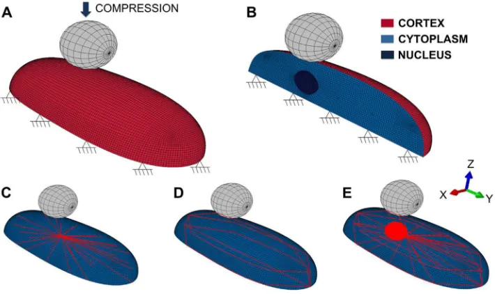
Indentation of one bead on the top of a single-adherent cell was simulated with Abaqus (Simulia, USA). For the 3D finite element single cell model, different components including the cytoplasm, the nucleus and the elements of the cytoskeleton, actin and microtubules, were considered (Fig. 1). In the model, continuous and discrete elements were used to represent the continuum media and the fibers of the cytoskeleton, respectively. The
simplified architectural structure of the elements inside the cell model was created based on microscopic observations of actin and microtubules distributions in adherent cells, therefore actin observed at the cell edge were defined as the cell cortex and interior actin fibers were defined as discrete actin bundles. The shape of the cell was defined as a semi-ellipsoidal form, 19 μm diameter long and about 8 μm wide. The nucleus was modeled with an ellipsoidal shape, which is consistent with measures reported by Caille and coworkers [27] and it is located 2.5 μm from the center along the longer axis of the cell. Hexahedral solid elements were used to represent cytoplasm and nucleus, and material properties (Table 1) were assumed to be continuous, homogeneous, isotropic and elastic. Discrete beam elements were used to model the microtubules structure originating from one common node near the nucleus, representing the centrosome to the cortex (Fig. 1). Microtubules are arranged in a star-shape and experimental observations showed that they grow until they reach the cortex where they interact with actin fibers [17,28]. The cortex, a thin layer at the periphery of the cell, is represented in the current cell model as a 0.2 μm thick shell. The cell membrane was
A
uthor Man
uscr
ipt
A
uthor Man
uscr
ipt
A
uthor Man
uscr
ipt
A
uthor Man
uscr
not considered in this model since it is softer and thinner than the adjacent cortex of actin and thus, its material properties were not considered to have a significant impact to resist mechanical deformation. In many cells actin is also present in long groups of individual actin fibers that are parallel to each other and joined by actin binding proteins, known as actin bundles. These bundles are normally localized around the cell periphery and are referred to as dense peripheral bands [29]. In this model, they are arranged in the whole cell above the cortex and both ends are anchored to it (Fig. 1). The actin bundles were modeled as discrete truss elements. The mechanical behavior of the actin bundles is reported to resist only to tensional forces and thus, this property was taken into account in the model. Material properties of all of the components used in this FE model are specified in Table 1. The mechanical behavior of living cells is mainly defined by the polymer fibers of the CSK that contribute to the mechanical stiffness of the cell [16,17,30,31]. Some of these fibers are internally prestressed even without application of an external load and that tensile stress is inherent to some filamentous structures. Previous experimental studies reported preexisting strain values of 0.24 ± 0.18 and a preexisting force level of 4.08 nN [29]. The force–strain relation was used to calculate the mechanical properties for the actin bundles of our model. The UMAT subroutine of Abaqus (Simulia, USA) was modified to define the stress–strain relationship for actin bundles taking into account the initial state of stress caused by the 24% of the initial strain of the filaments. Prestress defines cell contractility and was calculated to be 82 kPa. In this FE model, prestress is a key parameter to generate initial force and maintain cell shape.
2.2. Loads and boundary conditions
A 4.5 μm diametrical bead was modeled on the top of the cell (Fig. 1) to exert a stimulus and measure the reaction force and deformation of the cell for the different forces. The bead was moved toward the cell in the axial direction to establish the contact and further compression. This axial applied displacement was 0.5 μm, the same indentation depth applied during AFM experiments. Contact fully bonded properties were established between the cell surface and the microbead to guarantee that the bead can never detach from the cell. Zero displacement was applied to the bottom of the cell as a boundary condition, simulating full cell attachment to a rigid substrate (Fig. 1).
2.3. FE simulations
Eight different models were built to study the contribution of the individual CSK elements and their interconnectivity to cell response. For that, the elements of the cytoskeleton were removed one by one, as well as in combination of two. A model considering cytoplasm nucleus and the components of the CSK (actin cortex, actin bundles and microtubules) was used for control and compared with models where the different components of the CSK were removed from the cell one by one (to study interactions between components) and in combination of two (to evaluate the individual contribution of each component to cell integrity). Results were evaluated in terms of reaction force of the cell, which can be related to the cell stiffness, and in terms of deformation of the individual components to measure their contribution to the response of the whole cell. For direct comparison with experimental results, Young’ s modulus was calculated from the computed force-indentation curves using Hertz theory [32].
A
uthor Man
uscr
ipt
A
uthor Man
uscr
ipt
A
uthor Man
uscr
ipt
A
uthor Man
uscr
Cell culture of Fibroblasts (3T3-NIH) and osteosarcoma cells (U2OS-GFP actin), drug treatment with CSK-disruptors and AFM force-measurements methodology is described in detail in the Supplementary information.
3. Results
3.1. Implementation of computational approach and corroboration with AFM
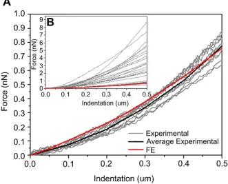
The single-cell FE model, which includes the cellular components of mechanical interest: actin cortex, actin bundles, microtubules, cytoplasm and nucleus, was used to predict force and deformation of a cell under compression (Fig. 1). Different material properties are considered for each cellular component (Table 1) to predict force and deformation from which the average numerical Young’ s modulus (E) was calculated using a modified Hertz model. The average Young’ s modulus obtained from the FE analysis was compared to the Young’ s modulus of two cell types with different morphologies, the U2OS-osteosarcoma cells and 3T3 fibroblasts (Fig. 2). From this composite numerical cell an average Young’ s modulus of 0.7 kPa was obtained for the whole cell. The average apparent Young’ s modulus calculated from AFM experiments was 3.8 ± 1.6 kPa for 3T cells and 1.3 ± 0.8 kPa for U2OS cells (with 0.1 Hz indentation rate, 0.5 μm indentation depth, N = 34).
The numerical predicted force-indentation curve matches the non-linear behavior of experimental data obtained with AFM for 3T3 fibroblasts (R2 = 0.98) and for U2OS cells (R2 = 0.99) (Fig. 2B). The average of the AFM force measurements for the two types of cells was calculated and compared to the numerical simulation. Statistical differences using unpaired t-Test were found for 3T3 fibroblasts (N = 16). However, no statistical differences were found between computational force prediction and average of force for U2OS cells (N = 18) and thus validates the proposed multi-structural model (Fig. 2A). Further
quantification of numerical CSK disruption was made with respect to this giving model organization and mechanical properties. The concept implemented to define the CSK structure in this FE model defines prestress as an essential parameter to generate initial force and maintain cell shape, although not essential to define the interplay between discrete components. Therefore, the simplified spatial morphology for the CSK structure resembles that of a living cell and the interplay between discrete components can be disrupted for the study of the role of individual components of the CSK inside cells.
3.2. Numerical study of the role of the individual CSK components to resist compression
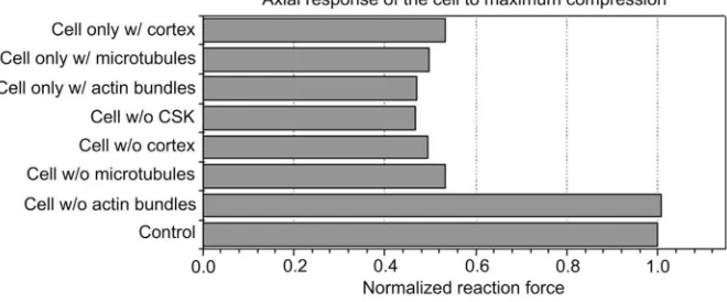
The contribution of each component of the CSK, actin bundles, actin cortex and microtubules to the cellular behavior was evaluated using the FE model (Fig. 3). The reaction force of a cell with complete CSK, considered as the control, was 5.3-times higher than a “cell without CSK”. The axial reaction force of a “cell without actin bundles” was similar to the axial reaction force of the control, showing minimal effect of this component to cell rigidity during compression. When the cortex was removed the reaction force was 5-times lower when microtubules were removed. None of the three components was capable of maintaining cell rigidity by itself, demonstrating that their response must be dependent on the presence of other components. Therefore, during compression, microtubules and actin cortex were essential to maintain cell force and rigidity.
A
uthor Man
uscr
ipt
A
uthor Man
uscr
ipt
A
uthor Man
uscr
ipt
A
uthor Man
uscr
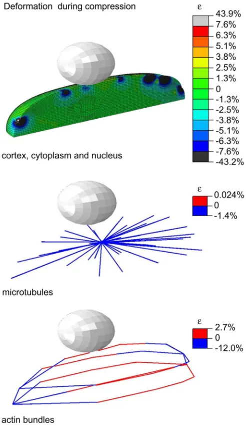
Deformation of cortex, nucleus and cytoplasm reached a maximum of about 40% (Fig. 4) for a 0.5 μm compression. These high strains are due to localized deformation of the nodes caused by the attached discrete elements of the cytoskeleton. Low strains in microtubules were predicted by the model which can be explained by microtubules’ high rigidity. As mentioned above, the interaction between microtubules and cortex is important for resisting deformation. Higher strains were observed for the actin bundles compared to strains observed in microtubules, highlighting the effect of this component on cell deformation although they do not propagate compressive forces for this amount of indentation due to the level of prestress they are subjected to.
3.3. AFM measurements and imaging
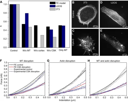
Force-indentation measurements using AFM were performed on 3T3 and U2OS cells before and after chemical disruption of the CSK components and apparent E was calculated (Fig. S1). After treatment with cytochalasin-D to disrupt actin, the apparent E of 3T cells was measured to be 4.5 ± 2.2-times lower than the control (N = 6) and 2.2 ± 0.7-times lower for U2OS cells (N = 7). After microtubule disruption with nocodazole, the E of 3T cells was 2.5 ± 1.1-times smaller than the control (N = 5) and 1.2 ± 0.2-times smaller for the U2OS cells (N = 5). After disruption with both drugs, apparent E of 3T cells was 7.7 ± 4.7-times smaller (N = 5) and 2.4 ± 0.3-times smaller for U2OS cells (N = 6). A paired sample t-Test indicated that all last set of measurements with drug for each cell were significantly different from control (p < 0.05, using a paired t-Test), except for the U2OS cells after disruption with nocodazole.
Fluorescence images of the cytoskeleton of both cells were taken before and after CSK disruption to confirm disruption and to evaluate differences in the CSK structure of the two cell lines. F-actin in the 3T cells was visualized with rhodamine-phalloidin, and F-actin in the U2OS cells were visualized with GFP-actin (Fig. 5B– E). Less quantity of stress fibers in the interior of the cells and more actin located at the edge of the cells was observed for the 3T cells (Fig. 5B) compared to the U2OS (Fig. 5D). In the U2OS, actin is arranged in stress fibers. When subjected to the same concentration of cytochalasin-D, actin networks were affected differently for the two cell lines. Treatment of 3T cells with cytochalasin-D disrupted mainly the actin networks at the cell edge (Fig. 5C), while the same concentration of drug disrupted the entire structure of F-actin in the U2OS cells (Fig. 5E).
3.4. Comparison between the model and AFM measurements for CSK disruption
The average apparent Young’ s modulus of cells with different rigidities is compared with the cell rigidity of the computational model (Fig. 5A). AFM measurements showed a decrease in cellular rigidity when the different CSK components were disrupted, as predicted by the current FE model (Fig. 5A). Since the model validation was previously shown, for accurate validation of the model after CSK disruption, computational predictions and experimental force-indentation relationship of U2OS cells were compared during control and then for each case of CSK component disruption (Fig. 5F–H). For statistically significance of the match between computational and experimental force-indentation curves, the p-value was calculated using an unpaired t-Test. The force-indentation curve of untreated U2OS cells (control) matches the curve predicted computationally, as seen in Fig. 2A. After CSK
A
uthor Man
uscr
ipt
A
uthor Man
uscr
ipt
A
uthor Man
uscr
ipt
A
uthor Man
uscr
disruption using the different drugs, the force-indentation curves obtained experimentally for these cells also match the predicted computational results for all the different conditions of the CSK disruption. The experimental range of curves obtained after cytochalasin-D exposure showed the largest variability. Only one of the force-indentation curves after microtubules disruption did not match the decrease in force predicted computationally (Fig. 5F).
4. Discussion
A key feature of this model is the structural stability defined for the CSK that accounts for the interconnectivity between the elements as well as allows changes of form and
organization of the individual components without collapsing the cell shape if they are removed. This type of fusion of models was previously done by McGarry et al., 2004 [18], by integrating continuum models with the tensegrity theory, where the CSK was represented to behave as a prestressed interconnected network. However, in order to have a stable structure, all the elements of the tensegrity model must bear either pure compression, such as the microtubules, or pure tension, as the actin filaments. Thus, no bending or torsion is allowed in these elements, as they all have to be straight and the loads can exclusively be applied to the joints of the interconnection between the elements. Although the tensegrity structure provided understanding of the relation between cell mechanics and biological functions [33], the molecular structure of the individual components of the CSK, that is essential for several cellular processes, is not taken into account. The current model improves this structural concept, as there is no restriction on the spatial distribution of the fibers. The application of forces is not restricted to the nodes of interconnection between discrete elements and a more realistic representation of the application of loads as in the experimental methods is achieved. The structure of actin cortex and bundles are
interconnected with the structure of microtubules and therefore, forces sensed in the entire CSK structure are transmitted to the continuous elements of the cytoplasm and nucleus. The role of the nucleus for signaling transmission is not considered in this model since the nucleoskeleton is not taken into account. Similarly, intermediate filaments, another CSK component, are not considered in the current model. Though they impart mechanical integrity to cells [5,34] for higher deformations [35,36], their mechanics are still under investigation [37].
The current model assembles information on how cells respond to force and deform under compression, and how force is transferred through CSK components and cytoplasm, into a single framework. Discrete elements, representing CSK fibers, are merged with the continuum and as a consequence localized high strains are obtained in the continuous elements of the cytoplasm and cortex, caused by the attached discrete elements of the CSK. The location of these high strains is on the nodes of interaction between CSK components at the cortex level. Therefore, it is important to see if these large strains that are equivalent to large stresses do not introduce discontinuities for the model accuracy: if the tension in the shell cortex in the current model is below the surface tension measured in cell membranes, then the shell would withstand those deformations without breaking or collapsing. The value of maximum von Mises measured in the cortex of the model cell was 433.3 Pa, which is far below the documented values of 2400 Pa for membrane surface tension [38]. Strains in the
A
uthor Man
uscr
ipt
A
uthor Man
uscr
ipt
A
uthor Man
uscr
ipt
A
uthor Man
uscr
remaining cytoplasm and nucleus are low, and above 5%. Low strains were also registered at the other components of the CSK. Putting together numerical quantification of cell
deformation and force on the different actin networks of the model help us understand experimental findings on force generation. When actin bundles are removed from our cell model, the force generated is about the same of an intact cell with all CSK components. At the same time, when present in the model these actin bundles sustain high deformation to resist compression, which is related to the fact that these elements are pre-stretched for the purpose of modeling prestress. From these results, we identify the prestress in the actin bundles as a requirement for force generation and the actin cortex essential to maintain cell rigidity. With this numerical approach the mechanical properties of the actin cortex can be distinguished from the role of actin bundles and microtubules under compression. Our results showed that the actin cortex together with microtubules, are the main components to resist compression.
Simulation of CSK disruption quantified the changes in the overall reaction force of the cell: when the bead is displaced 0.5 μm in compression, about 53% of the cell force is reduced when all three components of the CSK were removed. The results of our model during compression were corroborated with AFM experiments for the same amount of indentation. The apparent Young’ s modulus, when CSK was disrupted with nocodazole and
cytochalasin-D during our AFM experiments, decreased 58 ± 6% for U2OS cells and 76 ± 13% for 3T cells. The differences might be related to variation of the amount of CSK fibers of the two cell types, as well as to the concentration of drugs used in this study, which affect the initial rigidity (E) of the cells tested and therefore, the way their CSK is disrupted. For a more accurate analysis of the quantitative study during compression we need to take into account the disruption of the different actin networks for each cell type and the concentration of drug used. Fluorescence images of 3T cells with phalloidin-stained F-actin showed a large disruption of the actin in the cortex region, while inner actin fibers remained partially intact (Fig. 5B, C). The inner fibers that were not disrupted maintain their pre-stretched state to maintain cell shape and the effect of cell contractility is seen at the actin fibers at the cell edge. Computationally, 50% decrease in force is predicted for actin cortex disruption during compression while 71 ± 14% decrease in force was found for the apparent E of 3T cells with cytochalasin-D actin disruption. Fluorescence images of U20S cells with GFP-actin showed disruption of the entire assembly of actin networks when exposed to 0.5 μM of cytochalasin-D (Fig. 5D, E), with a decrease in apparent E of 49 ± 17% which matches the 50% decrease in force obtained with the FE model when actin cortex and actin bundles are removed from the cell. For both cell types, a decrease in cell elasticity is registered when microtubules are disrupted. The 53% decrease in force from the cell model matches the 52 ± 17% decrease in the apparent E of 3T cells but does not match the 21 ± 7% decrease found for U2OS cells. Further studies using fluorescence microscopy with
microtubules labeling will be required to relate with the numerical results and understand which mechanical properties of the microtubules (density, diameter of the fibers, E or spatial distribution) affect the rigidity of different cell lines. Despite these limitations, the model predicts the overall role of the fibers during compression and is in good agreement with evidences from AFM experiments, showing the major role of actin cortex as well as microtubules. Our compression results, where disruption of actin cortex is one of the main
A
uthor Man
uscr
ipt
A
uthor Man
uscr
ipt
A
uthor Man
uscr
ipt
A
uthor Man
uscr
contributors in the decrease in cell stiffness, are also in accordance with previous experimental studies that show the concentration of cytochalasin-D affects the actin structures disrupted in the cell and is cell type dependent. Together with AFM imaging, this numerical simulations can be used for targeting specific mechanical properties of the actin located at the cell edge that were believed to correspond to the actin cortex mechanical changes [7,39,40].
Distinct mechanical properties have been measured for different cell types, which can be related to their specific roles in a tissue. This includes variations in the thickness and rigidity of the cell cortex or the mechanical behavior of the microtubules or differences in the amount of stress fibers depending on the cell type. Nervous cells were shown to have single actin filaments without stress fibers and myocytes and osteoblasts have actin filaments bundled in differently thick stress fibers [41]. The material properties of each cellular components of this cell FE model could not be corroborated by experiments on one cell type. This is due to the difficulty of accurately measuring thickness and rigidity of cellular components in living cells. Computational force-indentation curve using material properties from Table 1, which gives a whole cell rigidity of 0.7 kPa, matched force-indentation curve of U2OS AFM measurements. A brief sensitivity analysis was also performed to evaluate the effect of the material properties of the cortex on cell response and to understand mechanical features from different cell types. Increasing either E of the cortex from 2 to 10– 18 kPa or cortex thickness from 0.2 to 1 μm computationally, matches AFM
force-indentation curves of 3T3. This cortex reinforcement of 3T cells predicted by the current model matches microscopic images of this cell type that showed higher actin distribution in the edge of 3T cells (Fig. 5B). Increasing either cortex elasticity or thickness provided information about forces generated by stiffer cells with rigidities in the range measured for 3T3 fibroblasts.
Future work will be conducted to model the dynamic behavior of CSK including the non-linear response of the cell in terms of stress–strain relationship demonstrated experimentally [42,43]. Experimental evidences of contribution of microtubules to maintain viscosity [5] and to define the time of recovery to equilibrium of a cell after external stimuli [44,45] are the basis to extend our study for time-analysis of the relaxation time of cells using these multi-structural cell model and CSK remodeling.
5. Conclusions
The multi-structural cell model explains the previously reported differences for the
mechanical role of each CSK component. This numerical approach isolates the specific role of the actin cortex for cell integrity from the remaining CSK networks. Changes in the mechanical properties of each CSK components allow us to have numerical information of the amount of force transmitted by each CSK component in different cell types. The model specifies the elementary nature of the mechanics of cell components to resist external stimuli and is the basis to integrate remodeling of the CSK during application of forces as a
superstructure onto this model. In conclusion, this new approach yields a unique perspective on studying the correlation of cellular mechanical properties and stress distribution within particular CSK components, and on the mechanisms of force propagation by cells.
A
uthor Man
uscr
ipt
A
uthor Man
uscr
ipt
A
uthor Man
uscr
ipt
A
uthor Man
uscr
Supplementary Material
Refer to Web version on PubMed Central for supplementary material.
Acknowledgments
This study was supported by Fundação para a Ciência e Tecno-logia (FCT) of Portuguese Ministry of Science and Technology (SFRH/BD/47264/2008), the European Research Council (ERC grant agreement No. 258321) and Villum Kann Rasmussen foundation (Grant no. 495289). We thank to W. P. Ng and Dr. K. Webster for helpful suggestions and discussion, and to Dr. H. Khayyeri for critical reading of the manuscript.
References
1. Janmey PA. The cytoskeleton and cell signaling: component localization and mechanical coupling. Physiol Rev. 1998; 78(3):763–81. [PubMed: 9674694]
2. Ingber DE, Tensegrity I. Cell structure and hierarchical systems biology. J Cell Sci. 2003; 116(7): 1157–73. [PubMed: 12615960]
3. Huang H, Kamm RD, Lee RT. Cell mechanics and mechanotransduction: pathways, probes, and physiology. Am J Physiol Cell Physiol. 2004; 287(1):C1–11. [PubMed: 15189819]
4. Pelham RJ, Wang YL. High resolution detection of mechanical forces exerted by locomoting fibroblasts on the substrate. Mol Biol Cell. 1999; 10(4):935–45. [PubMed: 10198048]
5. Wang N. Mechanical interactions among cytoskeletal filaments. Hypertension. 1998; 32(1):162–5. [PubMed: 9674654]
6. Charras GT, Horton MA. Single cell mechanotransduction and its modulation analyzed by atomic force microscope indentation. Biophys J. 2002; 82(6):2970–81. [PubMed: 12023220]
7. Kasas S, Wang X, Hirling H, Marsault R, Huni B, Yersin A, et al. Superficial and deep changes of cellular mechanical properties following cytoskeleton disassembly. Cell Motil Cytoskeleton. 2005; 62(2):124–32. [PubMed: 16145686]
8. Wang N, Tolić-Nu˛rrelykke IM, Chen J, Mijailovich SM, Butler JP, Fredberg JJ, et al. Cell prestress. I. Stiffness and prestress are closely associated in adherent contractile cells. Am J Physiol Cell Physiol. 2002; 282(3):C606–16. [PubMed: 11832346]
9. Wang N, Naruse K, Stamenović D, Fredberg JJ, Mijailovich SM, Tolić-Nųrrelykke IM, et al. Mechanical behavior in living cells consistent with the tensegrity model. Proc Natl Acad Sci U S A. 2001; 98(14):7765–70. [PubMed: 11438729]
10. Stamenović D, Mijailovich SM, Tolić-Nųrrelykke IM, Chen J, Wang N. Cell prestress II. Contribution of microtubules. Am J Physiol Cell Physiol. 2002; 282(3):C617–24. [PubMed: 11832347]
11. Collinsworth AM, Zhang S, Kraus WE, Truskey GA. Apparent elastic modulus and hysteresis of skeletal muscle cells throughout differentiation. Am J Physiol Cell Physiol. 2002; 283(4):C1219– 27. [PubMed: 12225985]
12. Takai E, Costa KD, Shaheen A, Hung CT, Guo XE. Osteoblast elastic modulus measured by atomic force microscopy is substrate dependent. Ann Biomed Eng. 2005; 33(7):963–71. [PubMed: 16060537]
13. Nagayama K, Matsumoto T. Contribution of actin filaments and microtubules to quasi-in situ tensile properties and internal force balance of cultured smooth muscle cells on a substrate. Am J Physiol Cell Physiol. 2008; 295(6):C1569–78. [PubMed: 18923059]
14. Mijailovich SM, Kojic M, Zivkovic M, Fabry B, Fredberg JJ. A finite element model of cell deformation during magnetic bead twisting. J Appl Physiol. 2002; 93(4):1429–36. [PubMed: 12235044]
15. Vaziri A, Gopinath A. Cell and biomolecular mechanics in silico. Nat Mater. 2008; 7(1):15–23. [PubMed: 18066070]
16. Karcher H, Lammerding J, Huang H, Lee RT, Kamm RD, Kaazempur-Mofrad MR. A three-dimensional viscoelastic model for cell deformation with experimental verification. Biophys J. 2003; 85(5):3336–49. [PubMed: 14581235]
A
uthor Man
uscr
ipt
A
uthor Man
uscr
ipt
A
uthor Man
uscr
ipt
A
uthor Man
uscr
17. Maurin B, Cañadas P, Baudriller H, Montcourrier P, Bettache N. Mechanical model of cytoskeleton structuration during cell adhesion and spreading. J Biomech. 2008; 41(9):2036–41. [PubMed: 18466907]
18. McGarry JG, Prendergast PJ. A three-dimensional finite element model of an adherent eukaryotic cell. Eur Cell Mater. 2004; 7:27–33. [PubMed: 15095253]
19. Ujihara Y, Nakamura M, Miyazaki H, Wada S. Proposed spring network cell model based on a minimum energy concept. Ann Biomed Eng. 2010; 38(4):1530–8. [PubMed: 20108165] 20. Viens D, Brodland GW. A three-dimensional finite element model for the mechanics of cell-cell
interactions. J Biomech Eng. 2007; 129(5):651–7. [PubMed: 17887890]
21. McGarry JG, Klein-Nulend J, Mullender MG, Prendergast PJ. A comparison of strain and fluid shear stress in stimulating bone cell responses – a computational and experimental study. FASEB J. 2005; 19(3):482–4. [PubMed: 15625080]
22. Bischofs IB, Schmidt SS, Schwarz US. Effect of adhesion geometry and rigidity on cellular force distributions. Phys Rev Lett. 2009; 103(4):048101:1–048101:4. [PubMed: 19659402]
23. Hu S, Chen J, Fabry B, Numaguchi Y, Gouldstone A, Ingber DE, et al. Intracellular stress tomography reveals stress focusing and structural anisotropy in cytoskeleton of living cells. Am J Physiol Cell Physiol. 2003; 285(5):C1082–90. [PubMed: 12839836]
24. Jonas O, Duschl C. Force propagation and force generation in cells. Cytoskeleton. 2010; 67(9): 555–63. [PubMed: 20607861]
25. Ingber DE. Cellular tensegrity: defining new rules of biological design that govern the cytoskeleton. J Cell Sci. 1993; 104(Pt 3):613–27. [PubMed: 8314865]
26. Prendergast P. Computational modelling of cell and tissue mechanores-ponsiveness. Gravit Space Biol. 2007; 20(2):43–50.
27. Caille N, Thoumine O, Tardy Y, Meister JJ. Contribution of the nucleus to the mechanical properties of endothelial cells. J Biomech. 2002; 35(2):177–87. [PubMed: 11784536]
28. Kaverina I, Rottner K, Small JV. Targeting, capture, and stabilization of microtubules at early focal adhesions. J Cell Biol. 1998; 142(1):181–90. [PubMed: 9660872]
29. Deguchi S, Ohashi T, Sato M. Tensile properties of single stress fibers isolated from cultured vascular smooth muscle cells. J Biomech. 2006; 39(14):2603–10. [PubMed: 16216252] 30. Stamenović D, Ingber DE. Models of cytoskeletal mechanics of adherent cells. Biomech Model
Mechanobiol. 2002; 1(1):95–108. [PubMed: 14586710]
31. Laurent VM, Hénon S, Planus E, Fodil R, Balland M, Isabey D, et al. Assessment of mechanical properties of adherent living cells by bead micromanipulation: comparison of magnetic twisting cytometry vs optical tweezers. J Biomech Eng. 2002; 124(4):408. [PubMed: 12188207] 32. Rosenbluth MJ, Lam WA, Fletcher DA. Force microscopy of nonadherent cells: a comparison of
leukemia cell deformability. Biophys J. 2006; 90(8):2994–3003. [PubMed: 16443660] 33. Ingber D, Heidemann SR, Lamoureaux P, Buxbaum RE. Opposing views on tensegrity as a
structural framework for understanding cell mechanics. J Appl Physiol. 2000; 89(4):1670–8. [PubMed: 11183860]
34. Fletcher DA, Mullins RD. Cell mechanics and the cytoskeleton. Nature. 2010; 463(7280):485–92. [PubMed: 20110992]
35. Janmey PA, Euteneuer U, Traub P, Schliwa M. Viscoelastic properties of vimentin compared with other filamentous biopolymer networks. J Cell Biol. 1991; 113(1):155–60. [PubMed: 2007620] 36. Wang N, Stamenović D. Contribution of intermediate filaments to cell stiffness, stiffening, and
growth. Am J Physiol Cell Physiol. 2000; 279(1):C188–94. [PubMed: 10898730]
37. Fudge DS, Gardner KH, Forsyth VT, Riekel C, Gosline JM. The mechanical properties of hydrated intermediate filaments: insights from hagfish slime threads. Biophys J. 2003; 85(3):2015–27. [PubMed: 12944314]
38. Lim CT, Zhou EH, Quek ST. Mechanical models for living cells – a review. J Biomech. 2006; 39(2):195–216. [PubMed: 16321622]
39. Callies C, Fels J, Liashkovich I, Kliche K, Jeggle P, Kusche-Vihrog K, et al. Membrane potential depolarization decreases the stiffness of vascular endothelial cells. J Cell Sci. 2011; 124(Pt 11): 1936–42. [PubMed: 21558418]
40. Oberleithner H, Callies C, Kusche-Vihrog K, Schillers H, Shahin V, Riethmüller C, et al.
Potassium softens vascular endothelium and increases nitric oxide release. Proc Natl Acad Sci U S A. 2009; 106(8):2829–34. [PubMed: 19202069]
41. Gardel ML, Shin JH, MacKintosh FC, Mahadevan L, Matsudaira P, Weitz DA. Elastic behavior of cross-linked and bundled actin networks. Science. 2004; 304(5675):1301–5. [PubMed: 15166374] 42. Pourati J, Maniotis A, Spiegel D, Schaffer JL, Butler JP, Fredberg JJ, et al. Is cytoskeletal tension a major determinant of cell deformability in adherent endothelial cells? Am J Physiol. 1998; 274(5 Pt 1):C1283–9. [PubMed: 9612215]
43. Trepat X, Deng L, An SS, Navajas D, Tschumperlin DJ, Gerthoffer WT, et al. Universal physical responses to stretch in the living cell. Nature. 2007; 447(7144):592–5. [PubMed: 17538621] 44. Ofek G, Wiltz DC, Athanasiou KA. Contribution of the cytoskeleton to the compressive properties
and recovery behavior of single cells. Biophys J. 2009; 97(7):1873–82. [PubMed: 19804717] 45. Rosenbluth MJ, Crow A, Shaevitz JW, Fletcher DA. Slow stress propagation in adherent cells.
Biophys J. 2008; 95(12):6052–9. [PubMed: 18805929]
46. Guilak F, Mow VC. The mechanical environment of the chondrocyte: a biphasic finite element model of cell–matrix interactions in articular cartilage. J Biomech. 2000; 33(12):1663–73. [PubMed: 11006391]
47. Stricker J, Falzone T, Gardel ML. Mechanics of the F-actin cytoskeleton. J Biomech. 2010; 43(1): 9–14. [PubMed: 19913792]
48. Pampaloni F, Florin EL. Microtubule architecture: inspiration for novel carbon nanotube-based biomimetic materials. Trends Biotechnol. 2008; 26(6):302–10. [PubMed: 18433902]
Appendix A. Supplementary data
Supplementary data related to this article can be found at http://dx.doi.org/10.1016/ j.biomaterials.2013.04.022.
A
uthor Man
uscr
ipt
A
uthor Man
uscr
ipt
A
uthor Man
uscr
ipt
A
uthor Man
uscr
Fig. 1.
FE model of a single cell, boundary conditions and displacement applied with the bead on the top of the cell. (A) Cell model with boundary conditions and representation of the movement of the bead for compression; (B) Section of the cell with the continuous elements; (C) Microtubules distribution; (D) Actin bundles distribution; (E) Interaction of actin bundles and microtubules and position with respect to the nucleus.
A
uthor Man
uscr
ipt
A
uthor Man
uscr
ipt
A
uthor Man
uscr
ipt
A
uthor Man
uscr
Fig. 2.
Validation of the model comparing numerical and AFM force-indentation curves of untreated cells. (A) The average of the force-indentation curves obtained for U2OS cells (black) with average rigidity of 1.3 ± 0.8 kPa (N = 18) matches the numerical prediction (red). The two curves are not statistically different (p > 0.05). Force-indentation curves obtained experimentally for those cells are consistent with the computed force-indentation relationship of the model. (B) Force-indentation curves of all the cells tested (N = 34) considering 3T cells (N = 16) and U2OS cells (N = 18) are presented. (For interpretation of the references to color in this figure legend, the reader is referred to the web version of this article.)
A
uthor Man
uscr
ipt
A
uthor Man
uscr
ipt
A
uthor Man
uscr
ipt
A
uthor Man
uscr
Fig. 3.
Contribution of each component of the cytoskeleton during compression and effect of interaction between the elements of the cytoskeleton. Axial force for maximum compression is compared for the different models.
A
uthor Man
uscr
ipt
A
uthor Man
uscr
ipt
A
uthor Man
uscr
ipt
A
uthor Man
uscr
Fig. 4.
Distribution of strain (major principal strains) in the cortex, cytoplasm and nucleus during maximum compression and in the discrete elements representing microtubules and actin bundles.
A
uthor Man
uscr
ipt
A
uthor Man
uscr
ipt
A
uthor Man
uscr
ipt
A
uthor Man
uscr
Fig. 5.
(A) Comparison of overall Young’ s modulus (E) obtained numerically and with AFM, before and after CSK disruption for 3T3 and U2OS cells. The E calculated for the living cells is an average of the E of all cells measured. The results for the control are normalized with respect to the average value obtained for each cell type in order to analyze the changes in cell rigidity when CSK components are disrupted. Fluorescence images of actin structures of 3T3-NIH fibroblasts (phalloidin staining) are used for (B) control with intact actin structures and high concentration of actin in the cell edge that can be related to the cortex, and (C) actin disruption after being exposed for 30 min to cytochalasin-D. Microscopic images of GFP-actin for U2OS cells (D) before and (E) after exposure to cytochalasin-D, during AFM experiments. Comparison of numerical and experimental force-indentation curves of U2OS cells with the same rigidity before and after disruption with (F) nocodazole, (G) cytochalasin-D and (H) both drugs.
A
uthor Man
uscr
ipt
A
uthor Man
uscr
ipt
A
uthor Man
uscr
ipt
A
uthor Man
uscr
A
uthor Man
uscr
ipt
A
uthor Man
uscr
ipt
A
uthor Man
uscr
ipt
A
uthor Man
uscr
[image:19.612.79.232.121.206.2]ipt
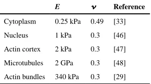
Table 1
Material properties of the continuous and discrete elements of the model cell.
E Reference
Cytoplasm 0.25 kPa 0.49 [33]
Nucleus 1 kPa 0.3 [46]
Actin cortex 2 kPa 0.3 [47]
Microtubules 2 GPa 0.3 [48]