i
DESIGN AND DEVELOPMENT OF ENERGY CONVERSION SYSTEM BY
USING THERMOELECTRIC GENERATOR (TEG)
MOHAMAD AIDIL BIN MOHAMAD SOHID
This Report Is Submitted In Partial Fulfillment of Requirement For The
Bachelor Of Electronic Engineering (Industrial Electronics)
Faculty of Electronics & Computer Engineering
University Technical Malaysia Melaka
v
ACKNOWLEDGMENT
First of all, thanks Almighty Allah for giving me strange and spirit to complete this thesis and my final year project “Design and Development of Energy Conversion System by Using Thermoelectric Generator (TEG)”.
Further, I would like to express my deepest gratitude and appreciations to Mr Hazli Rafis Bin Abdul Rahim and Madam Yusmarnita Binti Yusop lecturer of Universiti Teknikal Malaysia Melaka for being my supervisor for full support and invaluable guidance to ensure my final year project complete according to planning. I would like to say thank you for all lab technicians, for their accommodating in helping me if I have any problems during to completing my final year project in lab.
I am especially indebted to all classmates because give me full support. Other than that, I am very grateful to my parent and my family for helping me and support me during to completing my final year project and thesis. Without support from them, I cannot fulfil my final year project.
vi
ABSTRACT
vii
ABSTRAK
viii
TABLE OF CONTENT
CHAPTER CONTENT PAGE
INFRONT OF REPORT
ACKNOWLEDGEMENT
ABTRACT & ABTRAK
TABLE OF CONTENT
LIST OF FIGURES
LIST OF TABLES
LIST OF ABBREVIATIONS
i - iv v vi & vii
viii-x xi-xiii xiv
xv
I INTRODUCTION
1.1 Project Overview 1.2 Objective of Project 1.3 Problem Statement 1.4 Scope Of Project 1.5 Project Methodology 1.6 Thesis Outline
1 2 3 3 4 5
II LITERATURE REVIEW
2.1 Overview 2.2 Case Study 2.3 Boost Converter
2.4 Thermoelectric Generator Module
ix
2.5 PIC Microcontroller (16F877A) 2.6 MOSFET Switching
2.7 Temperature Sensor LM35 2.8 LCD Display
16 17-18 19-20 21-23
III METHODOLOGY
3.1 Overview
3.2 Data Collection Method 3.3 Gantt chart
3.4 Workflow 3.5 Block Diagram
3.6 Print The Circuit on PCB 3.7 Etching Circuit
3.8 Drilling Process
3.9 Installation the Component 3.10 Circuit testing
3:11 Soldering process
3:12 The steps to solder the component 3:13 Equipment on Soldering Step
24 25 25-26 26-28 29 30 30 31 31 31 31-32 32 33
IV RESULT AND DISCUSSION
4.1 Overview
4.2 Circuit Analysis
4.2.1 Thermoelectric module. 4.2.2 Boost Converter
4.2.3 Temperature Controller 4.3 Result
x
5.0 CONCLUSION & RECOMMENDATION
5.1 Project Conclusion 5.2 Recommendation
54-55 55
REFERENCES
APPENDIX A
APPENDIX B
APPENDIX C
APPENDIX D
xi
LIST OF FIGURES
NO TITLE PAGE
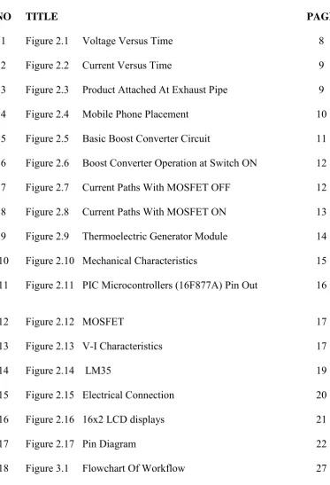
1 Figure 2.1 Voltage Versus Time 8 2 Figure 2.2 Current Versus Time 9 3 Figure 2.3 Product Attached At Exhaust Pipe 9 4 Figure 2.4 Mobile Phone Placement 10 5 Figure 2.5 Basic Boost Converter Circuit 11 6 Figure 2.6 Boost Converter Operation at Switch ON 12 7 Figure 2.7 Current Paths With MOSFET OFF 12 8 Figure 2.8 Current Paths With MOSFET ON 13 9 Figure 2.9 Thermoelectric Generator Module 14
10 Figure 2.10 Mechanical Characteristics 15 11 Figure 2.11 PIC Microcontrollers (16F877A) Pin Out 16
12 Figure 2.12 MOSFET 17
13 Figure 2.13 V-I Characteristics 17
14 Figure 2.14 LM35 19
15 Figure 2.15 Electrical Connection 20
16 Figure 2.16 16x2 LCD displays 21
17 Figure 2.17 Pin Diagram 22
[image:11.595.141.515.225.773.2]xii
[image:12.595.141.520.41.779.2]19 20
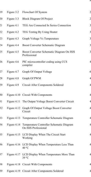
Figure 3.2 Flowchart Of System Figure 3.3 Block Diagram Of Project
28 29 21 Figure 4.1 TEG Are Connected In Series Connection 36 22
23
Figure 4.2 TEG Testing By Using Heater Figure 4.3 Graph Voltage Vs Temperature
36 37 24 Figure 4.4 Boost Converter Schematic Diagram 38 25 Figure 4.5 Boost Converter Schematic Diagram On ISIS
Professional 39
26 Figure 4.6 PIC microcontroller coding using CCS
compiler 40
27 Figure 4.7 Graph Of Output Voltage 40
28 Figure 4.8 Graph Of PWM 41
29 Figure 4.9 Circuit After Components Soldered 42
30 Figure 4.10 Circuit With Components 42 31 Figure 4.11 The Output Voltage Boost Converter Circuit 43 32
33
Figure 4.12 Graph Of Output Voltage Boost Converter Circuit
Figure 4.13 Temperature Controller Schematic Diagram
44
45 34 Figure 4.14 Temperature Controller Schematic Diagram
On ISIS Professional 46
35 Figure 4.15 LCD Display When The Circuit Start
Working 47
36 Figure 4.16 LCD Display When Temperature Less Than
40 ºC 47
37 Figure 4.17 LCD Display When Temperature More Than
39 ºC 48
xiii
40 Figure 4.20 Temperature Controller Display Result 50 41 Figure 4.21 Model Thermoelectric Device 51 42 Figure 4.22 Lamp Powered With Thermoelectric Device 52 43 Figure 4.23 Mini Speaker Powered With Thermoelectric
Device 52
44 Figure 4.24 Charging Smartphone With Thermoelectric
Device 53
45 Figure 4.25 Charging Powerbank With Thermoelectric
xiv
LIST OF TABLES
NO TITLE PAGE
1 Table 2.1 Experiment Result 8
2 Table 2.2 Performance values 15
3 Table 2.3 LM35 Parameter 20
4 Table 2.4 Pin Description 23
xv
LIST OF ABBREVIATIONS
CHAPTER I
INTRODUCTION
1.1 Project Overview
2
1.2 Objective of Project
There are several objectives involved in this project that should be focused to in order to achieve the design of the project.
i. To design a reliable portable device that can generate electricity by using the thermoelectric generator.
ii. To design the boost converter to step up small voltage. iii. To design the temperature controller for devices system.
The first objective is to design a portable device that can generate by using the thermoelectric generator and operate effectively. Thermoelectric module was used in this device system to convert thermal energy into electrical energy which it can be utilized at certain temperatures to operate and produce small voltage.
The second objective is use boost converter to increase small voltage generated by the thermoelectric module. The voltage generated from thermoelectric module too small and the boost converter is design based on the desired input and output. The PIC Microcontroller used to control the switching of MOSFET. The Pulse width modulation (PWM) is important where it will determine the output of boost converter based on input from thermoelectric module.
The third objective is to design the temperature controller for devices system. The thermoelectric module concept, it will operate when it has a temperature difference of hot and cold. The temperature controller is design to overcome the overheat problem.
3
1.3 Problem Statement
Nowadays, cause of the increasing awareness of global warming, we are finding ways to cut down their greenhouse gases emission. Thermoelectric is one of possibilities to recover wasted heat and convert it back to useful form of energy like electricity. This wasted energy can be used as an alternative energy to keep electronic equipment running.
Most of peoples facing problem to electronic devices when no electricity source. The source of electricity is very important for us to keep electronics device running every time and everywhere. As for this project, the proposed solution is to design and development of fire thermoelectric device for alternative energy can overcome the problem where it will be good option to cut down their greenhouse gases emission.
1.4 Scope of Project
In order to achieve the objective of the project, several scopes need to be identified. The scope of the project includes:
i. Develop the TEG converter system that able to produce an output in the range of 2V to 4V.
ii. Design and fabricate boost converter circuit. The boost converter circuit is fixed but still need to redesign to get the circuit comfortable with application.
4
1.5 Project Methodology
In order to complete this project, a number of methods used to ensure that projects are produced to achieve the target. It is divided into five phases:
Phase 1: Software Design
The software design for the project is to design the boost converter circuit and temperature controller by using Proteus software. The PIC simulation is used for analysis the outcome expected result and to control the PWM signal for boost converter circuit
Phase 2: Hardware Development
Construct thermoelectric converter and assemble the component for boost converter circuit and temperature controller circuit.
Phase 3: Hardware Testing
In this phase, testing functionality of each hardware
Phase 4: Hardware and Software Implementation
This phase involve each circuit having connection each other.
Phase 5: Data Analysis
5
1.6 Thesis Outline
This thesis report contains five chapters, consist introduction, literature review, methodology, result and discussion and last the conclusion of project. Each chapter explains detail about entire project to provide the understanding of the whole project.
Chapter one is introduction about the project. This chapter explain an overview overall of the project, objective of project, problem statement of project, scope of project, project schedule and thesis outline.
Chapter two present the literature review on the component that used in this project. The theory of all components, equipment and programming language that is used in this project also included. This chapter discuss all the source of article that related to this project and also reveals the product that been appeared in the market.
Chapter three discusses detail about projects methodology. It is also include project planning, and project finishing. All the progress is keep running follow the project planning. In this chapter, a flow chart is built to show the progress clearly and also use the Gantt chart for semester 1 and semester 2.
Chapter four is contain of the result and discussion overall for this final year project. In this chapter discuss about theory of thermoelectric concept and boost converter system that an important part to build this project. These chapters also discuss the result of thermoelectric temperature and output, boost converter output and the temperature controller function.
6
CHAPTER II
LITERATURE REVIEW
2.1 Overview
7
2.2 Case Study
The project is about Heat Energy Harvesting for Portable Power Supply (PosHEAT). This project designs a portable and compact thermoelectric generator that can be carried and used anywhere since we have the source of heat needed to convert .The energy produced by the waste heat will used to charge mobile phones and was stored in rechargeable batteries. The project concept, from waste heat will produces electrical energy as a renewable energy [1].
PosHEAT was designed with has attractive futures such as completely silent, no emission to produce electricity and no moving part, and reduced maintenance. The project use thermocouple concept, where voltage is produces in the presence of a temperature difference between two different metals. Seebeck made from Bismuth Telluride (Bi2Te3) are used where it the good material to generate more power. PosHeat will function generate electrical energy from heat energy when there is the different of temperature between the two sides of Seebeck. The project is use the temperature to produce power as an input [1].
8
[image:23.595.123.518.183.284.2]The results for the prototype are presented in Table 2.1. The table shown the difference temperature can produce difference value of voltage, current and power.
Table 2.1: Experiment Result No Difference Temperature
(ᴼC) Voltage (V) Current (A) Power (P)
1 15 1.9 0.35 0.67
2 30 2.5 0.40 1.00
3 45 3.0 0.48 1.44
4 60 3.8 0.52 1.97
5 75 4.4 0.62 2.73
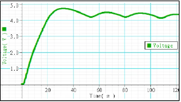
[image:23.595.204.493.418.581.2]Figure 2.1 show the output graph of voltage versus time. The voltage increase and stable above 4V for a long time.
9
[image:24.595.206.491.159.350.2]Figure 2.2 show the current versus time. The TEG start heating and the highest current will be on 0.6 A and it will drop to 0.4 A and stable.
Figure 2.2: Current Versus Time
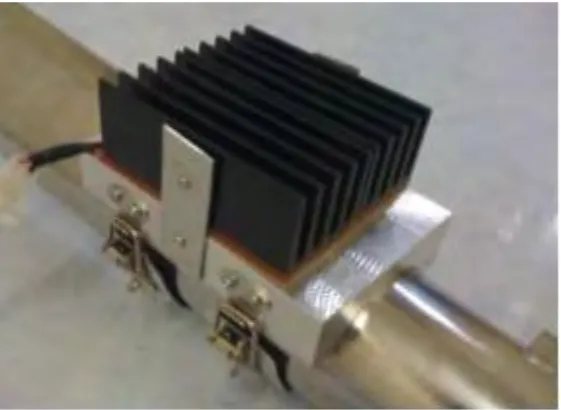
Figure 2.3 show the TEG device body come with heat sink was installed on the motorcycle exhaust pipe. The exhaust pipe can produce wasted heat and enough to heating the TEG.
[image:24.595.205.486.527.732.2].