i DECLARATION
“I, hereby declare that this thesis with title DEVELOPMENT OF PORTABLE
ELECTRICITY GENERATOR USING PELTIER FOR SMALL APPLICATIONis
a result of my own research idea concept for works that have been cited clearly in the references.”
Signature :………
ii
APPROVAL
This report is submitted to the Faculty of Engineering Technology of UTeM as a partial fulfilment of the requirements for the degree of Bachelor of Electrical Engineering Technology (Industrial Power) with Honours. The member of the supervisory committee is as follow:
………
iii
ABSTRACT
iv
ABSTRAK
v
DEDICATION
I dedicate this thesis to my family and friends who involved in sharing knowledge and support me doing my thesis.
vi
ACKNOWLEDGEMENT
The completion of this project could not been possible without the guidance and participation of so many people who sincerely helping me. Their contribution are sincerely appreciated and gratefully acknowledged. I would like to extent this appreciation to those who have helped me directly or indirectly in the completion of this project.
Special thanks to Puan Emy Zairah Binti Ahmad who is my supervisor for patiently helping and guiding me in completing this project as well as providing me necessary information regarding to my project which is “Development of Portable Electricity Generator using Peltier for Small Application”. Thank you for the knowledge and time spent in guiding me.
I would also like to thank my friends for their endless support, kind and understanding spirit during completing this project. Lastly, not to be forgotten, my special thanks go to my parents for their support, either morally, financially and physically, thank you.
vii
TABLE OF CONTENT
Declaration i
Approval ii
Abstrak iii
Abstract iv
Dedication v
Acknowledgement vi
Table Of Content vii
List Of Figures x
List Of Tables xiii
List Of Abbreviations, Symbols and Nomenclature xiv
CHAPTER 1: INTRODUCTION
1.0 Project Background 1
1.1 Problem Statement 2
1.2 Objectives 3
1.3 Scope 4
1.4 Project Significant 4
CHAPTER 2: LITERATURE REVIEW
2.0 Introduction 6
viii
2.1.1 Influence of Heat Leakage 9
2.2 Specification and Properties of thermoelectric generator (TEG) 10
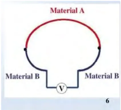
2.3 Thermoelectric generator (TEG) effect 11
2.3.1 Basic Concept of Thermocouple 13
2.4 Efficiency of Thermoelectric Power Generator 14
2.5 Application of Thermoelectric Generators 15
2.5.1 The experimental 17
2.6 Summary 17
CHAPTER 3: METHODOLOGY
3.0 Introduction 19
3.1 Flow Chart 19
3.2 Thermoelectric generator development of Seebeck effect 21
3.3 Full System Designed of Thermoelectric Generator Flow Chart 23
3.3.1 Thermoelectric Generator (TEG) 24
3.3.2 Step up USB DC 24
3.3.3 Rechargeable Battery and Switch 25
3.3.4 Load (small application) 26
3.4 Preliminary Result and Analysis 26
CHAPTER 4: RESULT AND ANALYSIS
4.0 Introduction 32
4.1 System Overview 32
ix
4.3 Hardware Result 33
4.4 Experimented Result 34
4.5 Discussion Result 44
CHAPTER 5: CONCLUSION AND RECOMMENDATION
5.0 Introduction 45
5.1 Conclusion 45
5.2 Recommendation 46
x
LIST OF FIGURES
2.1 Power generation mode 8
2.2 Seebeck effect 8
2.3 Generating Electricity from Thermoelectric Generator (TEG) 9
2.4 Operating principle of thermocouple 12
2.5 One Seebeck device "couple" consist of one N-type and one P-type 13
Semiconductor pellet.
2.6 A thermoelectric power generator 16
2.7 Experimental of Seebeck Effect 17
3.1 Flow chart of the project 20
3.2 An example Seebeck voltage generator 21
3.3 Full system designed of thermoelectric generator 23
3.4 Thermoelectric Generator (TEG) 24
3.5 Step-up USB DC 25
3.6 Example of Rechargeable Battery 25
3.7 Load 26
3.8 Data of one peltier- hot side placed with small candle and cold side 27
is room temperature
3.9 Data of one peltier- hot side placed with small candle and the cold side 28
placed with metal glass filled by water
3.10 Data of 4 cascaded peltier- hot side placed with small candle and 29
xi
3.11 one peltier- hot side placed with small candle and cold side is 30
room temperature
3.12 one peltier- hot side placed with small candle and the cold 31
side placed with metal glass filled by water
3.13 4 cascaded peltier- hot side placed with small candle and 31
cold side placed with metal glass filled by water
4.1 Step up USB 5V connected with source from peltier 33
4.2 Graph analysis all type of connection 35
4.3 Graph voltage produced (V) versus time (s) for 1 peltier 36
stand alone
4.4 Graph difference temperature (°C) versus time (s) for 1 36
peltier stand alone
4.5 Graph voltage produced (V) versus time (s) for 2 peltier 38
connected in series
4.6 Graph difference temperature (°C) versus time (s) for 2 38
peltier connected in series
4.7 Graph voltage produced (V) versus time (s) for 3 peltier 41
connected in series
4.8 Graph difference temperature (V) versus time (s) for 3 41
peltier connected in series
4.9 Graph voltage produced (V) versus time (s) for 4 peltier 43
connected in series
4.10 Graph difference temperature (°C) versus time (s) for 43
xii
xiii
LIST OF TABLES
2.1 References for data output from SP1848-27145 (ideal) 10
3.1 Data of one peltier- hot side placed with small candle and cold 27
side is room temperature
3.2 Data of one peltier- hot side placed with small candle and the cold side 29
placed with metal glass filled by water
3.3 Data of 4 cascaded peltier- hot side placed with small candle and 30
cold side placed with metal glass filled by water
4.1 Data analysis all type of connection 34
4.2 Data analysis for 1 peltier stand alone 35
4.3 Data analysis for 2 peltier connected in series 37
4.4 Data for 2 peltier connected in series with picture 39
4.5 Data analysis for 3 peltier connected in series 40
xiv
LIST OF ABBREVIATIONS, SYMBOLS AND
NOMENCLATURE
TEG = Thermoelectric Generator
TE = Thermoelectric
TEM = Thermoelectric Module
∆T = Difference Temperature
∆V = Difference Voltage
DC = Direct Current
Emf = Electromotive Force
1
CHAPTER 1
INTRODUCTION
1.0 Background
Electricity is one of the most important where science has given to mankind. Electricity has become useful and changed everyone’s life since the day it was discovered. The way to get electricity have a few of sources. There are from photo voltaic energy, non-renewable fuels, hydroelectric energy, nuclear energy and wind energy. Photo voltaic energy arise from sun’s sun rays. Fossil fuel arise from material that might be burned for instance coals. Hydroelectric arise from the produced energy in the water falls. Nuclear energy arise from the produced consequence of the nuclear energy station. Lastly, wind energy produced from wind mills.
2 across thermoelectric material can be converted directly into electrical power. Inside the peltier, the materials are made up from more than one pairs of p-type and n-type elements.
In other words, thermoelectric generate the electricity from a temperature difference and it is about how electrons move in a metal. Metals are good conductors because electrons can move freely within them, same as fluid in a pipe. When raised the pipe it will increased the potential energy and the water will flow downhill. In a thermoelectric material the same things happen to the fluid-like electrons when it is heated. These effects are not at all specific to semiconductors. However, semiconductors are particularly suitable for thermoelectric applications. The reason is that the nature of the current carriers in semiconductors can be manipulated. That is done by doping the material. In an n-type doped semiconductor, currents are carried by mobile electrons. In a p-type doped semiconductor, the currents are carried by mobile holes, quantum states from which electrons are missing. Electrons are negatively charged particles, but holes act as positively charged ones. That is because a negatively charged electron is missing from a hole.
Throughout the process of how peltier effect works, it shows that the thermoelectricity phenomenon have a big potential for green technology. Because, the source of this energy is from thermal energy where it arise from sun’s radiation. Green technology is very useful for the future of environment.
1.1 Problem Statement
3 of energy. Through this situation, people’s problem can be solved by changing their life style by using renewable energy for instance, use the thermal energy sources. In this project, thermoelectric generators (TEG) is used as a device for producing electricity. This thermoelectric generator (TEG) will produce current when there are temperature difference occur between both sides of the peltier. The higher the differences between both sides of temperature, the higher the electricity can be produced from the thermoelectric device.
This project focused on green technology which is produced energy without using fuels or any source that can harm environment. In addition, this project able to be a portable power generator for small application for example, lamp, charger battery and etc. Moreover, if someplace inland facing with problem to get power source to light up a lamp, this project can help to give an alternative for this issue.
1.2 Objectives
The objectives of this project are:
(a) to develop an electrical energy generator device using the concept of peltier for small application.
4 1.3 Scope
There are a few of objectives need to be achieved in this project, so it has some scope and limitation. For implementing this project, first step is designing the portable electricity generator sizing that use peltier or thermoelectric generator (TEG). The design of this project is very important to consider for suitable size because it is a portable device. Since it is a device that produce low energy, it is not suitable to have a large size. Then, the overall system and circuit will be designed by incorporate the peltier device with other element for a complete circuit. Failed of designing circuit will effected the operation of this project. Simulation for the design circuit will be presented before implementing the project. Other elements that used for this project are battery, switch, metal plate, regulator and load. If the circuit functioned as well, this project will moving on developing the project guided by the design of the overall system. For limitation of this project, if perhaps the circuit not work as expected. Finally, this project will be tested due to its performance for generating electricity.
1.4 Project Significant
6
CHAPTER 2
LITERATURE REVIEW
2.0 Introduction
7 In addition, the general utilization of fossil powers utilization by human exercises has influenced a difficult issues for air and ecological issues. Subsequently, a worldwide temperature alteration, nursery gas discharge, environmental change, exhaustion of ozone layer and corrosive rain pulverizing our surroundings. To stop the above effect of fiasco, thermoelectric (TE) vitality converters is proposed as one of the conceivable route to its capacity in changing over the warmth radiated from vehicles, electrical instruments and sun beams which is a non-renewable vitality that is not contaminated. The merits of this conversion lies in the solid-state operation, the gas-free emission, the vast scalability, the maintenance-gas-free-operation without any moving parts and chemical reactions, no damage to the environment and also a long life-span of reliable operation. As thermoelectric devices consist of solid-state materials and not have moving parts, they are silent, reliable, and scalable (Ken-ichi et al, 2016). However, the TE devices are still in the limited application because of the low energy-conversion efficiency and the corresponding high material cost.
2.1 Energy produced by Thermoelectric (TE)
A thermoelectric generator (TEG) also called as Seebeck generator is a device that convert heat which is a temperature difference directly into an electrical energy through a phenomenon called the Seebeck effect that is a form of thermoelectric effect (Uchida et al, 2016). Thermoelectric materials generate electricity while in temperature gradient. Keeping in mind the end goal to be a decent thermoelectric, materials utilized must have the one of a kind blend of both high electrical conductivity and low warm conductivity. What is more, so as to set up high voltage while in temperature angle, its warm conductivity must be low.
8 generated that is proportional to the temperature gradient (∆T) between the ends of the couple. Since, Seebeck effect is the basis for power generation.
Figure 2.1: Power generation mode
[image:22.595.212.424.443.636.2]9 How thermoelectric generator (TEG) produce electricity? When heat is applied to one of the two conductors or semiconductors, heated electrons will flow towards the cooler one side. If the pair is connected through an electrical circuit, direct current (DC) flows through that circuit. Figure 2.3 shown how electricity produce from thermoelectric when it was heated. The thermoelectric (TE) materials enable the conversion of the temperature difference into electrical energy through Seebeck effect (Wei et al, 2014). To improve the performance of the thermoelectric module, it’s being integrated with coolant to decrease the temperature of the bottom surface (Dr.K.Rathnakannan et al, 2014).
Figure 2.3: Generating Electricity from Thermoelectric Generator (TEG)
2.1.1 Influence of Heat Leakage
10 2.2 Specification and Properties of thermoelectric generator (TEG)
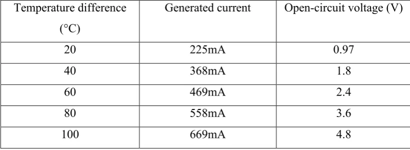
[image:24.595.113.523.448.598.2]The size of thermoelectric used in this report has small size with 40*40mm, light weight and long life. In the structure of thermoelectric, it has no moving parts. Besides, it is a device that high reliability and not pollute environment. Thermoelectric have two sides that need different temperature to generate any values of current. Higher the difference temperature between both sides, higher current can be generated by thermoelectric. From thermoelectric, it have two wires out from it. There are red wire and black wire. Red wire is for positive polarity and black wire is for negative polarity. It generate current when the temperature difference happened. The module of thermoelectric generator used in this report is SP1848-27145 with colour of white. For references, the generated current and open-circuit voltage for thermoelectric of this module as Figure 1 below:
Table 2.1: References for data output from SP1848-27145 (ideal)
Temperature difference (°C)
Generated current Open-circuit voltage (V)
20 225mA 0.97
40 368mA 1.8
60 469mA 2.4
80 558mA 3.6
100 669mA 4.8