UNIVERSITI TEKNIKAL MALAYSIA MELAKA
OPTIMIZATION OF STACKING SEQUENCE AND PLY THICKNESS
FOR COMPOSITE OF AEROSPACE USING DESIGN OF EXPERIMENT
This report submitted in accordance with requirement of the Universiti Teknikal Malaysia Melaka (UTeM) for the Bachelor Of Mechanical Engineering Technology
(Maintenance Technology) With Honours
by
WAN AMIRUL SAFWAN BIN W. MOHAMAD B071310354
910830-06-5093
i
ABSTRAK
ii
ABSTRACT
iii
DEDICATIONS
Most Elevated Exceptional Grateful To Both My Father and Mother Mr. W. Mohamad @ Wan Awang and Mrs Maimon binti Ismail.
iv
ACKNOWLAGEDGMENTS
Firstly, millions of thankful wishes to ALLAH S.W.T because with his permissions, I’m able to complete my final year project report.
Also, I am using this opportunity to express my gratitude to everyone who assist me throughout the course of this project. I am thankful for aspiring guidance from Mr. Saiful Naim bin Sulaiman and Mdm. Nor Hamizah binti Miswan, for providing me with invaluably constructive criticism and advice during the project work.
v
TABLE OF CONTENT
Abstrak i
Abstract ii
Dedication iii
Acknowledgement iv
Table of Content v-vi
List of Tables vii
List of Figures viii- ix
List of Abbreviations, Symbols and Nomenclature x
CHAPTER 1: INTRODUCTION
1.1 Project Background 1-2
1.2 Problem Statements 2-4
1.3 Objective of the Project 4
1.4 Scope of the Project 4
CHAPTER 2: LITERATURE REVIEW
2.1 Composite 5-7
2.2 Type of composite 7
2.3 Polymer Matrix Composite 7-9
2.3.1 Laminated composite 9-12
2.4 Design of Experiment (DOE) 12-14
2.4.1 Two-level Factorial Design 14-15
2.4.2 Box Behnken Design 16-17
2.4.3 Miscellaneous 18
2.5 Laminated composite manufacturing technique 18-23
2.6 Type of Engineering Test
vi
2.6.2 Bending Test 26-28
2.7 Simulations 28-29
CHAPTER 3: METHODOLOGY
3.0 Introduction 30-31
3.1 Choice of Design 32
3.2 Actual Test 33
3.2.1 Resin Infusion method (specimen preparation) 33-36
3.2.2 Tensile test 38
3.2.3 Bending Test 39
3.4 Statistical Analysis 40-41
CHAPTER 4: RESULT & DISCUSSION
4.0 Introduction 42
4.1 Result of Actual Experiment 42-44
4.2 Analysis of Result. 44-51
4.3 Optimization of the output data 51-52
CHAPTER 5: CONCLUSIONS
5.0 Introduction 53
5.1 Conclusion of Study. 53-54
5.2 Recommendation for further studies. 54
REFERENCES 55-58
vii
LIST OF TABLES
Table 2.1 Coded factor levels for a Box-Behnken design of 17
a three-variable system
Table 2.2 Tensile Specimen Geometry Requirements 24 Table 2.3 Tensile Specimen Geometry Recommendations 25
Table 3.1 Two-factor Miscellaneous experimental designs 32 Table 3.2 Equipment list of Resin Infusion method 34 Table 3.3 Planned dimension for specimen preparations based on Miscellaneous. 37
Table 4.1 Result for Tensile Actual test. 43
Table 4.2 Actual test data (input to design Expert). 44 Table 4.3 ANOVA table for Ultimate Tensile strength. 45
Table 4.4 ANOVA table for Max bending load. 45
viii
LIST OF FIGURES
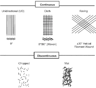
FIGURES 2.1 Typical reinforcement types 6
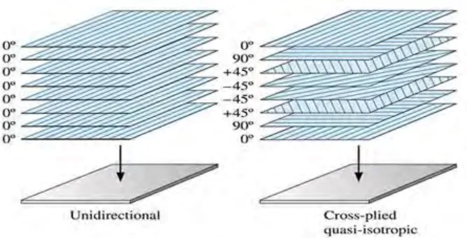
FIGURES 2.2 Type of Laminated composite ply arrangement 8
FIGURES 2.3 Schematic of Honeycomb Sandwich 9
FIGURES 2.4 Schematic of laminated composite 10
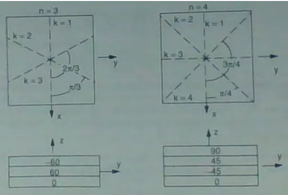
FIGURES 2.5 Bidirectional and unidirectional material properties 10 FIGURES 2.6 Example of Balance and symmetrical laminate 11 FIGURES 2.7 Example of Quasi isotropic laminate 12
FIGURES 2.8 Example of 22 design 15
FIGURES 2.9 The 23 factorial design 15
FIGURES 2.10 A three interlocking 22 factorial designs and central point 17 FIGURES 2.11 Schematic representation of a hand lay-up process. 19
FIGURES 2.12 Resin Infusion method 20
FIGURES 2.13 Autoclave molding process 22
FIGURES 2.14 Typical curing cycle for carbon/epoxy composites 22
FIGURES 2.15 Sample/coupon without tabs 24
FIGURES 2.16 Tensile Test Failure Codes/Typical Modes 25
FIGURES 2.17 A three-point loading system 26
FIGURES 2.18 Standard Flexural Test Specimen Drawing (SI) 27 FIGURES 2.19 Flexure Test Specimen Three-Part Failure Identification Code 27
FIGURES 3.1 Methodology flow chart 31
FIGURES 3.2 Resin Infusion set up diagram and actual pics. 35
FIGURES 3.3 Universal testing machine 38
FIGURES 3.4 Three-Point Bending Machine 39
FIGURES 3.5 Example of Half-normal plot of the factor effects 40
from the 24 factorial.
ix FIGURES 4.1 Specimen condition after test. 43 FIGURES 4.2 Normal probability plot of Ultimate Tensile strength 46 FIGURES 4.3 Normal probability plot of Max bending load. 46 FIGURES 4.4 Plot of residual vs predicted for Ultimate Tensile strength. 47 FIGURES 4.5 Plot of residual vs predicted for Max bending load. 47 FIGURES 4.6 Plot of predicted vs Actual for Ultimate Tensile strength. 48 FIGURES 4.7 Plot of predicted vs Actual for Max bending load. 48 FIGURES 4.8 Plot of Interaction for Ultimate Tensile strength. 49 FIGURES 4.9 Plot of Interaction for Max bending load. 49 FIGURES 4.10 Plot of 3D surface for Ultimate Tensile strength. 50 FIGURES 4.11 Plot of 3D surface for Max bending load. 50 FIGURES 4.12 Final Equation for Ultimate Tensile strength. 51 FIGURES 4.13 Final Equation for Max bending load. 51 FIGURES 4.14 3D plot of number of ply and stacking sequence 52
x
LIST OF ABBREVIATIONS, SYMBOLS AND
NOMENCLATURE
ANOVA - Analysis of Variance
UTeM - Universiti Teknikal Malaysia Melaka FTK - Fakulti Teknologi Kejuruteraan
No. - Number
N - Newton
DOE - Design of experiment UTM - Universal testing machine
σ - Stress
P - Pressure
A - Area
σ - Stress
ϵ - Strain
UTS - Ultimate Tensile strength MBL - Max bending load
L - Support span, mm
δ - Mid-span deflection
b - Width
1
CHAPTER 1
INTRODUCTION
1.1 PROJECT BACKGROUND
Composite in term of composite material signifies that two or more materials are combined on a macroscopic scale to form a better third material (Jones, 2008). In contrast to metallic alloys, each material retains its separate chemical, physical, and mechanical properties. The matrix, normally a form of resin, keeps the reinforcement in the desired orientation. It protects the reinforcement from chemical and environmental attack, and it bonds the reinforcement so that applied loads can be effectively transferred.
The primary reason composite materials are chosen for components is because of weight saving for its relative stiffness and strength (high strength and stiffness, combined with low density) also combination of the reinforcement and the matrix can be changed to meet the required final properties of a component. Ability to manipulate the resultant properties is the special features in composite materials.
Its high strength and light weight remain the best combination that entice a lot of industries such as aerospace, marine and automotive industries to used them, Moreover in those industries. It’s important to keep strength to weight ratio as high as possible
Composites material can be classified to few groups, there are three main groups of most common man-made composites; fiber reinforced polymer (FRP), metal matrix composites (MMC) and ceramic matrix composites (CMC). This study focuses on the influence of fiber architecture to the flexural and tensile properties of FRP specifically laminated materials. FRP are composite materials composed of heat-hardening or room temperature curing resins as matrix together with reinforcement materials.
2 lightweight structural applications and there are many cases in which the mechanical properties of composite materials are notably reliant on the strain rate. The maximum strength for composite materials show significant increment compared to the value under static loading conditions.
1.2 PROBLEM STATEMENTS
Firstly, the study is about an analysis of composite materials, and it is one of the hardest and complex processes (K.Kaw, 2006). A single result analysis and impact event can produce several different damage modes simultaneously. In the composite material the damages can hardly been detected, so, it is important to identify the factor that contributes to the damages. In automobiles and aerospace application it is very important because it would be very dangerous if it’s cannot be functional properly. To ensure its strength, tensile and bending strength test will be carried out.
The modern use of composite materials in manufacturing is not new, spanning several decades, the combination of fiber with a liquid matrix has been employed in a variety of applications, ranging from tried and true dried mud and straw (adobe bricks). Nonetheless, compared to legacy materials like steel, aluminum, iron and titanium, composites are still coming of age, and only just now are being better understood by design and manufacturing engineers. Further, composites are hindered by their non-isotropic nature, which makes them difficult to model and simulate (Isaac M.Daniel, 2006). However, composites physical properties, combined with unbeatable light weight make them undeniably attractive. Especially to Automotive and Aeronautics Companies. The chance to be able to produce a material with same properties with legacy materials but with less weight is enticing.
3 bending and tensile strength with minimum weight, similar study had been done by (Jane Maria Faulstich de Paivaa, 2005) the focus of its study is to compared the value of tensile strength of Different Carbon Fabric Reinforced Epoxy Composites.
The design and analysis of fibre-reinforced polymer composite structural members requires a detailed knowledge of the properties of the constituent materials which form the structural members. This presented the most problem in this study, where deep understanding of material properties and other knowledge needed to be learned to complete this studies. A composite material especially laminated composite is a type of material that the value of mechanical and physical properties could be manipulated by manipulating the composite parameter (thickness, orientation, materials, stacking sequence and etc) this made them more complicated then legacy materials, because legacy material mechanical properties cannot be change as long as it’s the same type. Unique nature of laminated composite materials have not been fully addressed in commercially available software. Composite materials are unique due to their ply-level, anisotropic, nonlinear stress-strain response (Jeffrey M. Staniszewski, 2012)
4 1.3 OBJECTIVES OF THE PROJECT
The project objectives are:
i. To design composite FEA model. In hyperworks for tensile and bending testing. ii. Varies design parameter and create DOE run based on Miscellaneous method
(Design Expert).
iii. Run actual testing based on DOE for tensile and bending strength.
iv. To analyze and optimize the DOE result and determine the importance of every parameter and its relations.
1.4 SCOPE OF THE PROJECT
The research is subjected to the following scopes:
i. Designing by using CAD software (CATIA/Solidwork). Design and simulation of composite using hyperworks.
ii. Create composite specimen for actual testing. iii. DOE design using Design Expert.
5
CHAPTER 2
LITERATURE REVIEW
2.1 Composite
A composite materials is a combination/fusion of two or more material that would produce better properties compared to those of the individual component (Barbero, 2011). It differ to metallic alloy in terms of its still carry its own separate chemical, physical, and mechanical properties (H.Staab, 1999). Modern composite usually consist of few constituent. Such as:
o Matrices/Matrix
Usually in a form of resin, keeps the reinforcement in the desired orientation. It protects the reinforcement from chemical and environmental attack, and it act as adhesive that bonds the reinforcement so that applied loads can be effectively transferred. Should able to protect fiber reinforce from mechanical damage and environmental effect, plus interfacial bond strength could increases the toughness of composite. (Harris, 1999)
o Reinforcements
Reinforcement fibers can be cut, aligned, placed in different ways to affect the properties of the resulting composite. Reinforcements is the material that has been impregnated in the matrix to lend its advantage (usually strength) to the composite.
o Cores
6 Figure 2-1: Typical reinforcement types
Usually constituents of a composites is arranged so that open or more discontinuous phase (reinforcement) are embedded in a continuous phase (matrix) (George H.Staab, 1999). The reinforcing phase provides the strength and stiffness. The reinforcement is usually a fiber or a particulate. Particulate composites have dimensions that are approximately equal in all directions. They may be spherical, platelets, or any other regular or irregular geometry. Particulate composites tend to be much weaker and less stiff than continuous fiber composites, but they are usually much less expensive. Particulate reinforced composites usually contain less reinforcement (up to 40 to 50 volume percent) due to processing difficulties and brittleness. In most case the reinforcement is usually stronger than matrix. As for Composite matrix material there is 3 type:
7 In a simple ways of compared from one to another it could be said that, Polymer have low strength and Young's ’modulus. Metal matrix is intermediate in strength, Young's ’modulus and has good ductility. As for ceramic matrix usually is Hard, strong, stiff and brittle.
2.2.0 Type of composite
There are few other criteria or terms needed to be fulfilled before one could be called composite materials. Firstly both of the material need to have reasonable proportions, secondly the materials need to have its own properties that is reasonably differ from another. Lastly, a synthetic is commonly produced by deliberately combining and uniting the material by various means
The definition given above is a basic definition of composite if that definitions is used, then composite would be so vast and encompassed things such as bricks, concrete, wood, and modern synthetic composite. A modern synthetic composite is divided to groups by a 3 distinct grouping that is divided based on the type of matrix (Autar K. Kaw, 2006).
Polymer Matrix Composite (PMC), Metal matrix composites (MMC) Ceramic matrix composites (CMC).
2.3 Polymer Matrix Composite
8 such as their length, strength, stiffness or based on their chemical compositions, the reinforce that used in polymer matrix composite is a thin diameter fibers and polymer type matrix (epoxy, polyester and etc) (K.Kaw, 2006). Structural composite also could be group into polymer matrix composite if the matrix materials is made from fibers. Structural composite is design to produce best engineering properties focus to fulfill its applications. Structural composite have also divided to a few groups, such as:
o Laminated
[image:19.612.161.495.486.656.2]Laminate structure could simply defined as a stack of plies of composites that is combine on top of each other. Also could be stated as stack of lamina composites that is combine on top of each other (Barbero, 2011). Composite material is different from an isotropic materials such as aluminum and titanium that has a uniform properties in all direction, composite material limit its strength and stiffness only in the direction of the fiber ((FAA), 2012). Unidirectional composites have most mechanical properties focused in one direction and are anisotropic in nature. Fiber reinforced composites can only approach the true isotropic nature of metals, if fiber orientation is designed to produces optimum mechanical properties as example bidirectional and multidirectional all the statement above is supported by ((FAA), 2012).
9 o Honeycomb Sandwich
[image:20.612.115.542.196.368.2]A sandwich-structured composite is a specially structured of composite materials that is fabricated by combined thin but stiff skins to a lightweight but thick core. The core is commonly shape as honeycomb, Hence the name.The focus of this study is the macromechanics of laminar composite.
Figure 2-3: Schematic of Honeycomb Sandwich
2.3.1 Laminated composite
10 sequence. Larger number of stacking sequence are possible if number of ply with chosen orientations increases. The strength and stiffness of a composite is mostly relying on the orientation sequence of the plies. If proper orientation sequence of plies is been made a strong and stiff advanced composite materials could be produced. In ((FAA), 2012) Studies shows that the fibers in a bidirectional material run in two directions, usually 90° apart. A plain weave fabric is an example of a bidirectional ply orientation. These ply orientations have strength in both directions but not necessarily the same have the same value. [Figure 2-5]
[image:21.612.207.444.360.497.2] [image:21.612.216.439.459.668.2]Aerospace composite structure often are made of quasi-isotropic materials, its because this types of ply orientations duplicate isotropic materials. The plies of a quasi-isotropic layup are stacked in a 0°, –45°, 45°, and 90° sequence or in a 0°, –60°, and 60° sequence. [Figure2-2]
Figure 2-4: Schematic of laminated composite
11 Based on journal of (H.Staab, 1999) there are few laminate design guidelines are considered as a basic for the design of the stacking sequences:
Symmetry: Whenever possible, stacking sequences should be symmetric about the mid-plane (middle of the laminated parts) material, angle and thickness of the layers are the same above and below the mid-plane.
Balance: Whenever possible, stacking sequences should be balanced, with the same number of +θ° and - θ° plies.
Cross ply laminate: fiber orientation of 0° and90° is arranged alternating.
Angle ply laminate: fiber orientation of +θ° and - θ° is arranged alternating, with same material, angle and thickness. Could be in Symmetric (even) or antisymmetric (odd).
Quasi isotropic laminate: Lamina is oriented in manner to produce an isotropic matrix with no less than 3 layers. Example of Quasi isotropic laminate is [0, ±60] and [0, ±45, 90] as shown in figure 2-7. And it do not matter if you change it to be Symmetric such as [0, ±60]S and [0, ±45, 90]S.
12 Figure 2-7: Example of Quasi isotropic laminate.
2.4 Design of Experiment (DOE)
Design of experiments (DOE) is a systematic method to determine the relationship between factors affecting a process and the output of that process. DOE is series of test that manipulate input variable of a system or case of study and the result of response variable are recorded (Telford, 2007), simply put, it is used to find cause-and-effect relationships. DOE is structured and organized way of conducting and analyzing controlled tests to recognize the factors that are affecting a response variable.
An understanding of DOE first requires knowledge of some statistical tools and experimentation concepts. It is vital for practitioners to understand basic DOE concepts so that DOE that analyzed in software programs could be understand better.
13 o Experimental domain is the experimental ‘area’ that is investigated (defined by the
variation of the experimental variables).
o Controllable input factors, or x factors, are those input parameters that can be modified in an experiment or process.
o Uncontrollable input factors are those parameters that cannot be changed, it’s fixed because of maybe environment factor for example room temperature.
o Responses, or output measures, are the result that need to be find in the study. o Hypothesis testing helps determine the significant factors using statistical
methods. There are two possibilities in a hypothesis statement: the null and the alternative. The null hypothesis is valid if the status quo is true. The alternative hypothesis is true if the status quo is not valid. Testing is done at a level of significance, which is based on a probability.
o Blocking and replication: Blocking is an experimental technique to increase precision by avoid/removing any unwanted variations in the input or experimental process. Replication of experiments, test is run multiple times, in order to get an estimate for the amount of random error that could be part of the process.
o Interaction: When an experiment has three or more variables, an interaction is a situation in which the simultaneous influence of two variables on a third is not additive.
There are few uses that comes from DOE. The main uses of design of experiments are discovering interactions among factors, screening many factors, optimizing a process, including evolutionary operations (EVOP) and designing robust products. DOE analysis also could be done by various software package such as JMP, Minitab, Design Expert, Anova TM and Hyperstudy (Proust, 2009). A few factor or parameter that would be manipulated in this experiment is:
o Number of ply o Stacking sequence