i
WEARABLE HAND GESTURE CONTROLLER
MUHAMMAD ALIUDDIN BIN AHMAD ALWI
This Report Is Submitted In Partial Fulfillment of Requirements For The Bachelor Degree in Electronic Engineering (Industrial Electronics)
UNIVERSITI TEKNIKAl. MALAYSIA MEL.AKA
ii
UNIVERSTI TEKNIKAL MALAYSIA MELAKA F AK.UL Tl KEJURUTERAAN ELEKTRONIK DAN
KE.JURUTERAAN KOMPUTER
BORANG PENGESAHAN STATUS LAPORAN
PROOEK SAR.JANA MUDA Il
Tajok Projrk
Sesi Pengajian
WEARABLE GESTURE CONTROLLER
1 1
15
Saya MUHAMMAD ALIUDDIN BIN AHMAD ALWI mengaku membenarkan Laporan Projek Sarjana Muda ini disimpan di Perpustakaan dengan syarat-syarat kegunaan seperti berikut: 1. Laporan adalah hakmilik Universiti Teknikal Malaysia Melaka.
2. Perpustakaan dt'benarkao membuat salinan untuk tujuan peogajian sahaja
3. Perpustakaan dt'benarkan membuat salinan laporan ini sebagai bahan pertukaran antara institusi pengajian tinggi.
4. Sila tandakan (
'1 ) :
D
SULIT*EJ
TIDAK TERllADTarikb: 8 JUN 201S
*(Mengandungi maklumat yang berdarjah keselamatan atau kepentingan Malaysia seperti yang tennaktub di dalam A.KT A RAHSIA RASMI 1972)
**'(Mmpidungi maklumal tabad yang Uellah diteobJbn ollcb organisasi/badan di mana penyelidikan dijalankan)
Disahkan oleh:
{OOPD
J:lllPEHYEUA)
SANI IRWAN BIN MD SALIMPensyarah Kanan
fikulti Kejuruteraan Elektronik & Kejuruteraan Komputer
Universiti Teknikal Malaysia Melaka
Hang Tuah Jaya
·~· 76100DurianTunggal
"'-- Melaka
iii
"Saya akui laporan ini adalah hasil kerja saya sendiri kecuali ringkasan dan
petikan yang tiap-tiap satunya telah sayajelaskan sumbemya."
Tandatangan
Nama Penulis
Tarikh
...
~
....:
...
.
...
.
: MUHAMMAD ALIUDDIN BIN AHMAD ALWI
iv
"I I we hereby declare that I have read this in my I our work is sufficient in
terms of scope and quality for the award of Bachelor of Electronic Engineering (Industrial Electronics)."
Signature
Name of Supervisor
Date
: EN. SANI IR.WAN BIN MD SALIM
v
ACKNOWLEDGEMENT
vi
ABSTRACT
vii
TABLE OF CONTENTS
CHAPTER TITLE PAGE
PROJECT TITLE I DECLARATION II ACKNOWLEDGEMENT V ABSTRACT VI TABLE OF CONTENTS VII LIST OF TABLES VIII LIST OF FIGURES IX
I INTRODUCTION 1
1.1 INTRODUCTION OF PROJECT 1
1.2 OBJECTIVES OF PROJECT 3
1.3 PROBLEM STATEMENTS 3
1.4 SCOPE OF PROJECT 4
1.5 THESIS 5
II RESEARCH BACKGROUND 6
2.1 INTRODUCTION 6
2.2 CONTROL OF OMNI-DIRECTIONAL ROBOT USING ACCELEROMETER SENSOR ON ANDROID SMARTPHONE 7
viii
2.4 HAND GESTURE CONTROLLED SPEED AND
DIRECTION OF MOBILE 9
2.5 SKPS IN PS2 CONTROLLER STARTER KIT 10
III METHODOLOGY 12
3.1 INTODUCTION 13
3.2 PROJECT FLOW CHART FOR PSM 1 13
3.3 ACCELEROMETER 16
3.3.1 General Description 16
3.4 ARDUINO MICROCONTROLLER 18
3.4.1 Arduino UNO Communication 20
3.4.2 Arduino UNO Programming 20
3.4.3 Physical Characteristics 21
3.5 TRANSCEIVER 21
3.5.1 Pin Signals 24
3.5.2 Configuration of XBEE by using XCTU Software 25
3.6 MICROCONTROLLER (PIC18F4550) 32
IV RESULTS AND DISCUSSION 33
4.1 RESULTS 33
4.2 DISCUSSIONS 50
V CONCLUSION AND RECOMMENDATION 53
5.1 CONCLUSION 53
ix
xi
LIST OF TABLES
NO TITLES PAGE
3.1 XBEE pin signals 24
3.2 Parameter configuration 30 4.1 Analog input (Accelerometer sensors) and the output to robot 35
xi
LIST OF FIGURE
NO TITLE PAGE
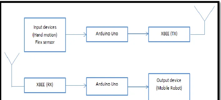
1.1 Block diagram for the whole system 4
2.1 Accelerometer glove sensor 9
3.1 Flowchart of PSM 1 methodology 13
3.2 Flowchart of project implementation 14
3.3 Block diagram of overall system 15
3.4 Accelerometer ADXL335 sensor 16 3.5 Functional block diagram of ADXL335 accelerometer 17
3.6 Arduino UNO microcontroller 18
3.7: Arduino UNO PIN specification 19
3.8 Input and output port for arduino UNO board 19
3.9 XBEE PRO S1 model 20 3.10 Mechanical drawing of XBEE 22
3.11 XCTU shortcut on desktop 25
3.12 XCTU selected menu 26
3.13 XCTU launch tab 27
3.14 Dialog box for successful Test/Query Operation 28
3.15 Selecting the function set 29
3.16 Transmitter (remote control) flowchart operation 30
3.17 Receiver (robot) flowchart operation 31
3.18 PIC18F4550 pin diagram 32
4.1 The final product of controller 34
4.2 The voltage supply to the Arduino UNO 34
4.3 Step 1 to measure the threshold value for the sensor 36 4.4 Code for measuring the threshold value of sensor 37 4.5 The circuit diagram for measuring the threshold value 38
4.6 Accelerometer ADXL sensor diagram 38
xi
4.8 The analog input of acceleration when move to (x-axis @ FOWARD) 40
4.9 The analog input of accelerometer when move to
(-x-axis @ BACKWARD) 40
4.10 The analog input of the accelerometer when move to (y-axis @ RIGHT) 41
4.11 The analog input of accelerometer when move to (-y-axis @ LEFT) 41 4.12 The STOP position of the wearable controller using accelerometer sensor
and output through Arduino UNO software 43
4.13 The FOWARD position of the wearable controller using accelerometer
sensor and output through Arduino UNO software 44
4.14 The BACKWARD direction of the wearable controller using accelerometer
sensor and output through Arduino UNO software 45
4.15 The RIGHT direction of the wearable controller using accelerometer sensor
and output through Arduino UNO software 47
4.16 The LEFT direction of the wearable controller using a accelerometer sensor
and output through Arduino UNO software 49
1
CHAPTER 1
INTRODUCTION
Chapter 1 covers the introduction part of this Final Year Project of Degree. . It contains the overall view of the project from its initiation, method and devices utilized in this project.
1.1Introduction of project
2
the capability to move around in their environment and are not fixed to one physical location and it can be found in industry, military and also in university that do research on it.
There are many types of mobile robot navigation and this report will just focusing on Manual remote or tele-operated. According to Consortium on Cognitive Science Instruction (CCSI), tele operated robots are controlled remotely by a human being. Controlling mobile robots through teleoperation is a challenging task that demands a flexible and efficient user interface as well as a reliable connection. Teleoperation requires a user interface to translate operator commands to the robot and provide feedback from the robot to the operator [1].
Controller is a device that is used to control devices from certain ranges. The remote control signals can be sent through wired or wirelessly. A There is no doubt that wired controller provide a more reliable connection and much faster compared to wireless controller but somehow it is not practical for some application especially for mobile robot application. The limitations are due to the distance constraints and the wired might get snagged or cut. Wireless controller has longer distance coverage depending on the device specifications that being used but there is a potential that the transmission speeds can suffer from outside interference. Wireless connection is also more expensive compared to wired connection.
3
This makes point to point communication easy. Serial data is sent to the XBee router (or end device) connected to the PIC and received by coordinator.
1.2Objective
The objectives of this project are:
1. To develop a controller that control using hand motion.
2. To use XBee device to make wireless and wearable controller. 3. To use accelerometer for find the axis of hand motion.
1.3 Problem Statement
4
1.4 Scope of Project
[image:17.595.143.497.361.521.2]The Wireless Wearable Hand Motion Controller uses XBee and accelerometer. The main reasons using XBee is this device can covers range to 750m for outdoor line of sight and the frequency band of this device is 2.4 GHz. This is very suitable for outdoor usage especially for mobile robot application because it can provide a reliable connection. The accelerometer use in this project because to detect the magnitude axis and the direction of hand motion. The figure 1 shows the whole system of wearable Hand Motion controller that consist two parts, transmitter and receiver. This controller used Arduino UNO and XBee to create the communication protocol between the microcontroller of the transmitter and microcontroller of the receiver.
Figure 1.1: Block diagram for whole system
1.5Thesis
5
Chapter 1 is about introduction of the project. The basic idea about the project is
being explained in this chapter including the objective and scope of this project.
Chapter 2 is about the literature review on the type of device being used for similar
project. This section contains the literature review and methodologies that have been collected from different sources for the development of this circuit design.
Chapter 3 is about the design and methodology of the project.
Chapter 4 is about the analysis for all the obtained result.
6
CHAPTER 2
RESEARCH BACKGROUND
2.1 INTRODUCTION
In completing this project, some background researches have been done on several resources. The theory and description plus detail about the project have taken as guidance in completing this project. By this chapter, an overview of some application that similar to the project.
7
2.2 Control of Omni-Directional robot using Accelerometer sensor on Android Smartphone [3]
By referring to this project, it using accelerometer sensor on Android smart phone with helps of Wi-Fi as medium to transmit and receive information data. The control of robot the robot movement is done by sending the accelerometer sensor value changes to the robot via a wireless network.
The advantage of using this technology is the cost for developing the controller is more cheap compared to Wireless Wearable Hand Motion Controller because it only using accelerometer in an android smart phone. Nowadays, people can affordable to buy this Android smart phone because the price much cheaper. By using the phone that someone already has to control movement of robot can save and reduce the cost for developing the robot controller.
8
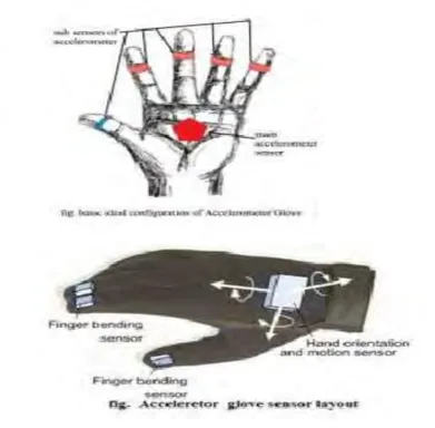
2.3 Gesture Based Wireless Virtual Mouse Controller Using Accelerometer [4]
9
Figure 2.1: Accelerometer glove sensor
2.4 Hand gestures controlled speed and direction of mobile robot [5]
In this paper, the main goal of this project is to control the speed and direction of robot using different hand gesture by using accelerometer. In this project, it uses XBEE as utilization for communication between robot and accelerometer that placed at human hand or medium to transmit data signal between transmitter and receiver. In this project also, camera to recognize the gesture is used to provide geometrical information to the robot.
10
lot of benefit of using this technology compared to other technology such as high in range that can be cover up, the network can be secure from hijacking of an authorized person and this technology is low in cost but the technology that they provide is great. In this project, the gesture that going to use must be capture and save first before start controlling the robot. The weakness of this technology is the gestures that already save and input gesture must match to control mobile robot. If not, the robot will not moving at all. Besides that, it is hard to coding the programming and does the image processing compare when using only XBEE technology and PIC18f4550 that are going to use in my project.
2.5 SKPS in PS2 Controller Starter Kit [6]
In this paper present about Play Station 2 offer a good human manual gesture as an input for control system. This kit can easily found at a play store. There is some issue that rising. The major issue is that the new protocol to connect with PS2 socket is needed as PS2 socket is very unique and hard to find in a market place. Cytron Technologies has designed and invented PS2 controller Starter Kit called SKPS. This inventory is developing to overcome the problem.
SKPS is a device from Cytron Technologies that has low current consumptions which is less than 150mA. This device communicates with its microcontroller through 5V TTL UART and need simple inquiry command and button status feedback for host to process. This device (SKPS) fully compatible either with wired or wireless.
11
The SKPS is PS2 Starter Kit that uses Bluetooth connection between transmitter and receiver as its transmission medium. According to Michigan State University, Bluetooth's discovery protocol lets devices automatically find and start interacting with each other. This unintentionally exposes access and data to unauthorized users, will lead to a risk for potential hijacking incidents and identity theft. This theory is supported by the George Mason University; Bluetooth technology is Omni-directional, meaning that their signals cover all directions. When other devices are present in the same space, signals from Bluetooth can get distorted in the direction of its intended recipient.