UTeM Library (Pind.1/2007)
UNIVERSITI TEKNIKAL MALAYSIA MELAKA
BORANG PENGESAHAN STATUS TESIS*
JUDUL: DESIGN AND MODELING OF MULTIPLE TANK FOR FLUID CIRCULATION SYSTEM USING PI, PD & PID CONTROLLER
SESI PENGAJIAN : 2007-2008
Saya JANNATUNNAIM HARUN
mengaku membenarkan tesis (PSM/Sarjana/Doktor Falsafah) ini disimpan di Perpustakaan Universiti Teknikal Malaysia Melaka (UTeM) dengan syarat-syarat kegunaan seperti berikut:
1. Tesis adalah hak milik Universiti Teknikal Malaysia Melaka .
2. Perpustakaan Universiti Teknikal Malaysia Melaka dibenarkan membuat salinan untuk tujuan pengajian sahaja.
3. Perpustakaan dibenarkan membuat salinan tesis ini sebagai bahan pertukaran antara institusi pengajian tinggi.
4. **Sila tandakan (√)
SULIT
TERHAD
TIDAK TERHAD
(Mengandungi maklumat yang berdarjah keselamatan atau kepentingan Malaysia yang termaktub di dalam AKTA RAHSIA RASMI 1972)
(Mengandungi maklumat TERHAD yang telah ditentukan oleh organisasi/badan di mana penyelidikan dijalankan)
(TANDATANGAN PENULIS)
Alamat Tetap:
35,KG KEMELONG,08200 SIK KEDAH
Tarikh:
Disahkan oleh:
(TANDATANGAN PENYELIA)
Cop Rasmi:
Tarikh: _______________________
APPROVAL
This PSM submitted to the senate of UTeM and has been as partial fulfillment of the
requirements for the degree of Bachelor of Manufacturing Engineering
(Robotic &Automation) with honours. The members of the supervisory committee are as
follow:
………
(Muhamad Arfauz A Rahman)
DECLARATION
I hereby, declared this thesis entitled “Design and Modeling of Multiple Tank for Fluid Circulation System Using PI, PD and PID Controller” is the results of my own research
except as cited in references.
Signature : ……….
Author’s Name : Jannatunnaim Bt Harun
ABSTRACT
Nowadays tank level control is one of the important system which been
used widely in industry. There are many applications in industry that uses this
system such as waste water treatment, food processing beverage, dairy, filtration,
effluent treatment, and nuclear power generation plants, pharmaceutical industry,
water purification system, industrial chemical processing and spray coating,
boilers and automatic dispensing and replenishment devices. Many weaknesses
have been found especially when come to overflow, leakage and others.
However this control system keeps developed to replace ordinary system
which applies mechanical function in controlling in order to improve system’s
reliability. From the project, the comparisons between the system without
controller and the system by using three controllers that are PI, PD and PID is
shown in the graph plotted for each. The comparisons also strengthen by the
overflow graph, which shows whether or not the system is having overflow.
The report started with the introduction to the project, literature review,
methodology, case study, system design and simulation, result and discussion,
ABSTRAK
Pada masa kini , kawalan paras air merupakan salah satu sistem yang
penting yang digunakan secara meluas di industri. Terdapat pelbagai aplikasi di
dalam industri yang menggunakan sistem ini seperti loji rawatan air,kawalan
tangki industri dan lain-lain. Pelbagai kelemahan telah dikenalpasti terutama
apabila melibatkan lebihan aliran, kebocoran dan lain-lain
Walaubagaimanapun , sistem kawalan ini terus berkembang untuk
menggantikan sistem yang sedia ada dimana fungsi mekanikal telah diaplikasikan
untuk mengawal sistem dan penambahbaikan kebolehan fungsi sesuatu sistem.
Daripada projek yang dijalankan, perbandingan antara sistem yang tidak
mempunyai controller dan sistem yang telah ditambah dengan penggunaan tiga
controller iaitu PI, PD dan PID telah ditunjukkan di dalam setiap satu graf.
Perbandingan ini juga dikukuhkan dengan graf lebihan aliran, yang menunjukkan
sama ada sesuatu sistem itu mengalami lebihan aliran atau tidak.
Laporan ini dimulakan dengan pengenalan kepada tajuk, kajian literature,
kaedah kajian,kajian kes, pembangunan rekabentuk, keputusan dan analisis,
DEDICATION
I dedicated this PSM thesis to my beloved parents ,Harun B. Hj Ismail and
Zaleiha Hj Ahmad , my siblings and not forgotten to my sources of inspiration
ACKNOWLEDGEMENTS
Alhamdulilah, with the helps and blessings from Allah S.W.T ,I had managed to
complete this PSM with successfully. First of all, I would like to thank my
beloved parents, for their concern all over the time. Not forgotten to all my
siblings, who had me a lot supporting me physically and morally.
I also want to thank Mr Muhamad Arfauz Bin Abdul Rahman as my supervisor
PSM for supervised me all along this project ,and provides helps, guides and
suggestions for completing PSM.All the supports and motivatiton that been given
to me are greatly appreciated.
Also not forgotten,En Asmawi and En Salleh from Bukit Sebukor Water
treatment Plant for giving a permission to conduct the case study at the Bukit
Sebukor Water Treatment Plant.
Finally ,thanks to all my friends who had helped me directly or indirectly in
TABLE OF CONTENTS
Abstract………..………...……i
Abstrak………..ii
Dedication……….iii
Acknowledgements………...…iv
Table of Contents ………v
List of Figures………..viii
List of Tables………....ix
List of Abbreviations, Symbols, Specialized Nomenclature………....x
1. INTRODUCTION……….1
1.1Project Introduction………...……...1
1.2 ProblemStatement ……… ………2
1.3 Objectives ………...2
1.4 Scope and limitationn………...………..3
1.5 Thesis Outline ………...4
1.6 Layout of the Thesis………..5
2. LITERATURE REVIEW……….6
2.1 Introduction……….…...6
2.2 Control System design………...6
2.3 Responses characteristics……….7
2.4 Trasient Responses………...12
2.4.1.Properties………...13
2.5 Level Control Systems………....14
2.6 Water Treatment Plant ………15
2.6.1 Sedimentitaion………15
2.2.2 Filtration………...16
2.8.PID Controller……….19
2.9.1 Loop tuning………...22
2.10 PI controller……….24
2.11 PD controller ………...25
2.12 Simulink……….26
2.13 Getting started Simulink……….27
2.14 Block Diagram construction………...28
2.15 Concluding remark………..29
3. METHODOLOGY………..30
3.1 Introduction………..30
3.2 Project Design………..30
3.3 System Design……….…….32
3.4 Project Methodology………33
3.4.1 Research……….33
3.4.2 Interview………33
3.4.3 Case Study ……….33
3.4.4 Observation ………...33
3.5 Tools………...34
3.5.1 Internet………...34
3.5.2 Journals……….34
3.5.3 Books……….34
3.5.4 Software……….34
3.6 Project Planning………...35
3.6.1 Project Planning for Projek Sarjana Muda 1 (PSM 1)………...36
3.6.2 Project Planning for Project Sarjana Muda 2 (PSM 2)……….… 38
4. CASE STUDY………..40
4.1 Introduction………..40
4.2 General system………...41
4.3 lamella Filtration system………..43
5.SYSTEM DESIGN & SIMULATION………45
5.1 Introduction……….45
5.2 System Development………..47
5.3Development Of Simulink Block Diagram………..48
5.4Summary………..52
6.RESULT &DISCUSSION………...53
6.1Introduction……….…53
6.2Analysis………..….53
6.3Summary……….…58
7.CONCLUSION &SUGGESTIONS………..59
7.1Introduction………59
7.2Conclusion………..60
7.3Suggestions &Recommendation……….61
LIST OF FIGURES
2.3(a) Open loop system 7
2.3(b) Closed loop system 8
2.5 Typical Level System 14
2.6.2 Basic Water Treatment Plant 17
2.8(a) PID Controllers 19
2.8(b) Step Responses PID 20
2.11 Step Responses PI 25
2.12 Step Responses PD 25
6.2(a) A system without a controller 54
6.2(f) A system with PID controller 57
6.2(d) A system with PI controller 56
6.2(c) A system with PD controller 55
6.2(b) Overflow signal PI 56
6.2(e) Overflow signal PD 55
6.2(g) Overflow signalPID 57
LIST OF TABLES
1 Increasing Parameter 23
2 Ziegler-Nichols method 24
3.5 Gantt chart for PSM 1 37
LIST OF ABBREVIATIONS, SYMBOLS,
SPECIALIZED NOMENCLATURE
FKP - Fakulti Kejuruteraan Pembuatan
PSM - Projek Sarjana Muda
PID - Proportional-integral-derivative controller
PI - Proportional –integral
PD - Proportional –Derivative
CHAPTER 1
INTRODUCTION
1.1 Project Introduction
Nowdays industrial application of liquid level control abound example in waste
water treatment food processing beverage,dairy,filtration,effluent treatment,and nuclear
power generation plants, pharmaceutical industry, water purification system, industrial
chemical processing and spray coating, boilers and automatic dispensing and
replenishment devices.
Level and flow control system is a technique used to control the level and flow of
circulation systems for variety of purposes such as to pretend from overflow. Most of
field in the fluid level and flow system are still applying the mechanical control devices,
but the most probably problem comes to overflow.
In this project, starting from conducting case study at Bukit Sebukor Water
Treatment Plant and the implementation of three controllers to see the better
1.2 Problem Statements
Most of field in the fluid level and flow systems are still applying the mechanical
control devices such as valves,flowmeter,pump,water tank and the most probably
problem comes to overflow .
In this project, there are three controllers will be used to control the level water
tank to the desired value. A performances of water level by adding the three controllers
will be analyzing by using SIMULINK software.Moreover,the analyze result will also
compared with the theoretical result.
1.3 Objectives of project
The objectives of this project basically can divide into four, which are:
a) To conduct case studies that using this system.
b) To improve the water level tank by using PI,PD &PID.
c) To evaluate current designed fluid circulation systems for Bukit Sebukor Water
Treatment Plant.
d) To apply the knowledge gained from the research studies to improve the current
1.4 Scopes and Limitations of Project:
The scopes of this project are :
a) Collect Data
Before starting the project, a case study will be done to collect the information about the
fluid system. One of suitable place to conduct the case study at Bukit Sebukor Water
Treatment Plant. Some of information will be getting by interview the technician on duty.
The limitation of the current system will be identify and consideration for improvements
later.In other study on internet,books,journal also be done to collect the information.
b) Develop Block diagram and Simulation
Block diagram and simulation were developed on PSM 2 by the aid of Simulink.The
block diagram including basic system and by adding three controller to see the
performances.
The limitation of this project included:
a) Limitations
The system concentrated only on controlling the desired value at the water tank level.
b) Controller:
1.5 Thesis Outline
Thesis outline is a summary of every chapter was described to introduce about the
chapter. Chapter one (1) introduced about the basic theory, the objectives of this project,
problem encounter, and the content of the project. Chapter two (2) is about literature
review about control system design,waste water treatment,PI,PD and
PID,SIMULINK.Chapter three(3) it will desribe about the whole method of process that
used throught this project.Chapter (4) will explain about case study have been conducted
at Bukit Sebukor Water Treatment Plant.Chapter five(5) will perform with design
development and step design development with simulation.Chapter six(6) will continue
with result and discussion about performances of three controllers. Moreover, a
comparison between the simulation result and also will discuss in this chapter. The final
chapter (7) will be the conclusion for this project, where further recommendation and
1.6 Summary
The project title as “Design and Modelling Of Multiple Tank Control by using
PI,PD and PID controllers. The project objective is to improve the design for water level
tank by using PI,PD &PID . Besides, it also involves the simulation of design . In order
to complete this project, many journals have to go through, SIMULINK simulation study
CHAPTER 2
LITERATURE REVIEW
2.1 Introduction
In this chapter consists of literature review about a control system design,water
treatment plant,PID controller and SIMULINK software. The concluding remarks is
included in the last section.
2.2 Control System Design
A Control system consists of subsystems and processes (or plants) assembled for
the purpose of controlling the outputs of the processes. Advantages of control systems
likes can move large equipment with precision that would otherwise impossible, elevators
carry us quickly to our destination, automatically stopping at right floor. Control systems
build for four primary reasons like power amplification, remote control, convenience of
input from and compensation for disturbances. [S.Nise,2004]
a) Power amplification –A radar antenna, positioned by the low power rotation of the knob at the input, requires the larger amount of power for its output rotation. A control
system can produce the needed power amplification, or power gain.
b) Remote Control-Robots designed by control systems principles can compensate for human disabilities. Control systems also useful in remote or dangerous locations. For
example remote-controlled arm can be used to pick up material in radioactive
c) Convenience of input form-Control systems can also be used to provide convenience by changing the form of the input. For example in a temperature control systems, the
inputs is heat. Convenient position input yields a desired thermal output.
d) Compensation for disturbances-The systems must be able consider an antenna that points in a commanded direction.
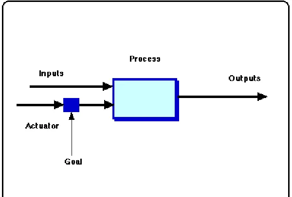
2.3 Responses characteristics and systems configurations
Two major configuration of control systems are open loop and closed loop:
Figure2.3(a): Open loop system
a) Open- loop
Open-loop systems its start with a subsystem called subsystems called an input
transducer by refering to figure 2.3(a), which converts the form of the input to that used
by controller. The controller drives a process or plant. The input sometimes called the
references, while the output can call the controlled variable. The disturbance called
[image:21.612.157.457.293.496.2]yield the algebraic sum of their input signals using associated signs. Example of
open-loop systems are mechanical system consisting of a mass, spring, and hammer with a
constant force positing the mass, spring, and damper with constant force positioning.
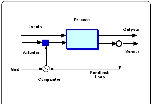
Figure2.3(b):Closed Loop Systems
b) Closed-loop
Closed loop namely very sensitive to disturbances and inability to correct for
disturbances may be overcome in closed systems. The input transducer converts the
form of the input to the form used by the controller. The first summing junction
algebraically adds the signal from the input to the signal from output, which arrives
via the feedback path, the return path from the output to the summing junction. Refer
to the figure 2.3(b) the output signal is subtracted from the input signal. The result is
generally called the actuating signal, but both the input and output transducer have
unity gain (that is the transducer amplifies its input by 1), the actuating signal value
equal to the actual difference between the input and output. Under this condition the
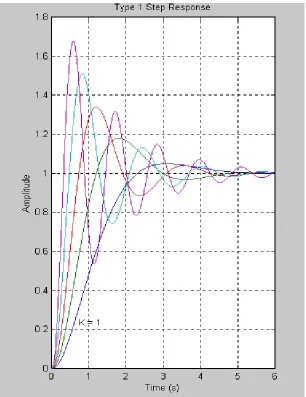
[image:22.612.147.463.164.382.2]2.4 Trasient Response
In electrical engineering and Mechanical Engineering, a transient response or natural
response is the response of a system to a change from equilibrium. Specifically, transient
response in Mechanical Engineering is the portion of the response that approaches zero
after a sufficiently long time (i.e., as t approaches infinity). (Contrast with steady-state
[image:23.612.154.460.195.592.2]response) by referring to the figure 2.4 below.
Figure 2.4:Trasient Responses
a) Underdamped
An underdamped response is one that oscillates within a decaying envelope. The more
underdamped the system, the more oscillations and longer it takes to reach steady-state.
Here Damping Ratio is always < 1 as refer to the figure 2.4 below.
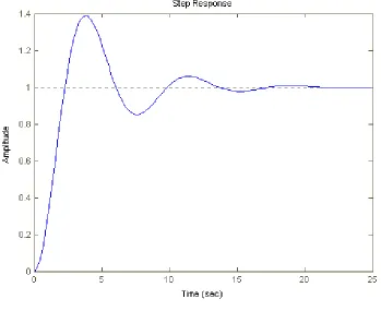
Figure 2.4 (a):Underdamped
b) Undamped
This function has pole at the origin has comes from the unit step input and two imaginary
input and two imaginary poles that comes from system by referring to the figure 2.4 (c)
[image:24.612.115.464.194.479.2]