Rochester Institute of Technology
RIT Scholar Works
Theses
Thesis/Dissertation Collections
2005
Data Aggregation and Cross-layer Design in WSNs
Carter May
Follow this and additional works at:
http://scholarworks.rit.edu/theses
This Thesis is brought to you for free and open access by the Thesis/Dissertation Collections at RIT Scholar Works. It has been accepted for inclusion
in Theses by an authorized administrator of RIT Scholar Works. For more information, please contact
Recommended Citation
Data Aggregation and Cross-layer Design in WSNs
by
Carter May
A Thesis Submitted
m
Partial Fulfillment of the
Requirements for the Degree of
Advisor:
Fei
Hu
Master of Science
m
Computer Engineering
---Dr. Fei Bu, Assistant Professor
Committee Member:
---
Marcin Lukowiak
Dr. Marcin Lukowiak, Assistant Professor
Committee Member:
_S_h_a_n_c_h_ie_h_J_aL-y_Y_a
n~g",--____________________ __
Dr. Shanchieh Jay Yang, Assistant Professor
Department of Computer Engineering
Kate Gleason College of Engineering
Rochester Institute of Technology
Rochester, NY
Release Permission Form
Rochester Institute of Technology
Data Aggregation and Cross-layer Design in WSNs
I, Carter May, hereby grant pennission to the Wallace Library of the Rochester Institute of
Technology to reproduce this thesis, in whole or in part, for non-commercial and non-profit
purposes only.
Carter May
Carter May
Table
of
Contents
TableofContents 1
ListofFigures 3
Chapter 1 Introduction 5
1 Abstract 5
2 Data Aggregation 6
3 Cross-Layer Optimized Design 6
4 Research
Methodology
65 Thesis Organization 7
Chapter 2 BackgroundandRelated Research 8
1 Wireless Sensor Networks 8
1.1 Common Network Topologies 8
1.2
Clustering
81.3 Trees 10
1.4 Ad Hoc Peer Networkvs.WSN 10
2 Data Aggregation 12
2.1 Data Aggregation
Timing
143 Cross-Layer Design 17
3.1 Traditional Network Model
-OSI Stack 17
3.2 MAC-layer design in WSNs 19
4
Summary
20Chapter 3 A Novel
Timing
Control for Optimal Data Aggregation 211 Problem Statement 21
2 Assumptions 23
-2.1 Cluster Size 24
3 Proposed Time Synchronization Algorithm 27
3.2 Control Parameter Refresh Rate 30
3.3 Finite State Machine ImplementationofAlgorithm 31
3.4 LevelofAggregationChosen
by
Sink 343.5 Height-based Differential Analysis 35
4
Energy
AnalysisofProposedTiming
Synchronization Algorithm 385 ApplicationsandExamples 46
Chapter 4 Cross-layer Design 49
1 Introduction 49
1.1 Traditional Network Model 49
1.2
Existing
WorkonCross-Layer Design 501.3 WSNMAC layer design 51
2 Our Proposed
Routing
OptimizationUsing
MAC Layer Information 53 3 Our Proposed MAC Layer OptimizationUsing Routing
Layer Information 553.2 Optimized
Sleep
Schedule 573.3 Proposed Route-aware MAC Optimization: FSM Control 60
3.4 Proposed Route-aware MAC Optimization: Protocol 61
4 Mathematical Analysis 62
4.1 Formulae 62
4.2 Visualization 62
5
Summary
63Chapter 5 OPNET SimulationofData Aggregation
Timing
Control 641 Simulation Design Requirements 64
2 Locationfor
Aggregating
Data 652.1 Between MACand
Routing
Layer 652.2 Inthe
Routing
Layer 652.3 Betweenthe
Routing
andApplication Layer 653 Simulation Implementation Overview 66
3.1 Intelligent Optimization BasedonLate Packets 69
4 SimulationDetails 69
4.1 Packet Format 69
4.2 Node FSM 70
4.3_ Sink FSM 71
5 OPNET Simulator Implementation 72
5.1 Sensor Node Simulation Model 72
5.2 Sink FSM 73
5.3
Routing
Layer 766 SimulationResults 78
6.1 ProofofConcept 79
6.2 PerformanceComparison 82
6.3 ComparisonResults 84
7
Summary
89Chapter 6 ConclusionandFutureWork 91
1 DataAggregation
Timing
Control 912 Cross-Layer Optimized Design 91
3 Future Work 92
List
of
Figures
Figure 1: SimpleTree Network 9
Figure 2: TypicalWSN
Using
aClustering Topology
9Figure3: Simple Network
Query
Response,
No Aggregation 13Figure4: Unbalanced NetworkwithPotential
Timing
Problem 14Figure5: Response Times for Several Aggregation Schemes 16
Figure 6: Simple NetworkwithPotential Aggregation
Timing
Problem 22Figure 7: Simple TreeNetwork 24
Figure 8: TreeSizevs.Cluster
Complexity
25Figure9:
Setup
vs.DataCollection Phases 28Figure 10: FSM#1 33
Figure 11: FSM #2 33
Figure 12: FSM #3 34
Figure 13: Unbalanced
Tree,
Aggregation Example 35Figure 14: NetworkwithUnbalanced Tree 36
Figure 15: Chain Plus Child Near Leaf 37
Figure 16: Chain Plus Child Near Sink 37
Figure 17:
Energy
Savingsvs.PercentageofAggregation 42Figure 18: NumberofMessages Receivedvs.Aggregation Period 43
Figure 19: Simplified NumberofMessages Receivedvs.AggregationPeriod 43
Figure 20: Convergence Timefor FSM #1 44
Figure 21: Convergence Time for FSM #2 45
Figure22: Convergence Time for FSM #3 46
Figure 23: HotspotCreated
by Routing
Algorithm 54Figure24:
Topology
withLikely
Channel Contention Problem 55Figure 25:
Energy
SavingswithVariably Participating
Nodes 57Figure 26: Example Route 58
Figure 27: Original
Sleep
Schedule 59Figure 28: Optimized
Sleep
Schedule 59Figure29: Finite State Machine 60
Figure 30: Idle
Listening Energy
vs.Duty
CycleandActive Route 63Figure 31: Idle
Listening Energy
vs.Connectivity
andActive Route 63Figure 32: Node FSM 70
Figure 33: Exampleof
Query
Propagationfrom SinktoLeaves 71Figure34: OPNET ImplementationofNode FSM 73
Figure 35: Simulated NetworkLayout 74
Figure 36: Data Sink Node Model 74
Figure 37:OPNET ImplementationofData Sink 75
Figure38: OPNET Implementationof
Routing
Layer 78Figure 39: NumberofResponses Reduced
Dynamically
79Figure40: Timeout Period Reduced
Dynamically
80Figure41: NumberofResponses Increased
Dynamically
81Figure42: Timeout Period Increased
Dynamically
81Figure 44: Timeout
Period,
n_opt=10 86Figure 45: Timeout
Period,
TimeAverage,
n_opt= 10 87Figure 46: Timeout
Period,
nopt=8 88Figure 47: Numberof
Responses,
TimeAverage,
nopt=Chapter 1 Introduction
1
Abstract
Overthepastfew years,advancesinelectrical engineering haveallowed electronicdevices toshrinkin bothsize and cost. It has becomepossibletoincorporateenvironmental sensors into asingledevicewith a microprocessor andmemorytointerpretthedataand wirelesstransceivers tocommunicatethedata. These "sensornodes"
have becomesmall andcheapenoughthatthey
can be distributed in verylarge numbers intothe areato bemonitored and can beconsidered
disposable. Once
deployed,
thesesensor nodes shouldbeabletoself-organizethemselvesintoa usable network. These "wirelesssensornetworks,"
or
WSNs,
differ fromother adhocnetworksmainly inthewaythattheyare used. Forexample, inadhocnetworks of personal computers, messages are addressedfromonePCtoanother. Ifa message cannotberouted, thenetworkhas failed. In
WSNs,
dataabouttheenvironmentisrequestedby
the"datasink."If anyor multiple sensor nodes can return an informativeresponseto this request, thenetworkhassucceeded. A
networkthatisviewedintermsofthedata itcandeliverasopposedtotheindividual devicesthat makeit up has beentermeda
"data-centric"
network[26]. The individualsensor nodesmay fail
to respond to a query, oreven
die,
aslong
as the final result is valid. The network is only considered useless when no usabledatacanbe delivered.In thisthesis,wefocuson twoaspects. Thefirst is data aggregation with accuratetiming control. Inordertomaintaina certaindegreeof servicequalityand a reasonablesystem
lifetime,
energy needs to be optimized at every stage of system operation. Because wireless communication consumes a major amount ofthe limited
battery
powerforthese sensornodes,we proposeto limittheamount ofdatatransmitted
by
combiningredundantandcomplimentarydata as much as possible in order to transmit smaller and fewer messages.
By
using mathematical models and computer simulations, we will show that our aggregation-focused protocoldoes, indeed,
extend system lifetime. Our secondary focus isa study of cross-layerdesign. Wearguethattheextremelyspecialized use ofWSNsshould convince us nottoadhere
to thetraditionalOSI networkingmodel. Throughourexperiments,we will showthatsignificant
2
Data Aggregation
The first issue we have investigated in this thesis work is related to the issue ofData Aggregation. Themostimportant issue in Wireless Sensor Networks is energyconsumption. To
this end,many networkingschemes attempttominimizetheamount ofdatatransmitted
by
using dataaggregation. Thistradesoffdatafreshnessanddelay
forsavingsinenergy,becausereportsfromsensor nodesthatarriveat anaggregatingnodemay havetobe heldthereforsome period
oftime before
being
reportedso thatadditional reportsmay reach theaggregatorfrom slower1 nodes. Weproposetouse an intelligenttimerand somehigh-level knowledgeofthenetworktoimplementan efficient aggregation timingcontrol protocol. Ourprotocol aims to
dynamically
changethedataaggregation periodaccordingto theaggregation quality. The datasink willissue
requeststhatincludebothadesirednumber of responses and a maximumtimeinwhichitwishes
to receive them. In some situations, the sink may only require responses from a few sensor
nodes out ofthe
field,
butthe timelinessoftheseresponsesisstillimportant.Aggregating
nodes attempt to provide as many responses as possible within time constraints, which also allowsmaximum aggregation and energy savings. Responses that cannot be provided in time are
ignored andthe sinkis responsible for specifyingmore relaxed timing constraints for itsnext
query.
3
Cross-Layer Optimized Design
Inthisthesis,inadditionto thetimingcontrol scheme addressed above, we aimtodefinea
customized cross-layer network model for WSNs that reduces overall power consumption
by
making anyseparatelayersaware of usefulinformation fromotherlayers. Weintendtodesigna
network model that integrates routing,
MAC,
and other operations with the goal of overall systemefficiencyandlow energyconsumption. InformationavailableintheMAC layerwillbeused tomake more efficientrouting layer decisions. Lower-layer information more accurately describesthecondition ofthe network,so shouldbetightlyintegratedwithhigherlayers
4
Research
Methodology
1
Weusethe term"slower"heremerelytodenotethata report of a related eventtakeslongertoreachthe aggregator. This may becausedbythenetworktopology,theTDMA schedulingpolicy,orphysically lost
We intendtoverifyourideas both mathematicallyandusingcomputer simulations. Wewill
usetheOPNETsimulatorto implementa sensor network with ourdataaggregation algorithms
[31]. Our OPNET model will allow easy implementation of various routing and MAC
algorithms,as well as new aggregation algorithms astheyare proposed. Wewill also useMatlab toprogram andverifyour numerical analyses.
5
Thesis Organization
Therest ofthis thesisisorganizedasfollows. In Chapter 2we presentthestate oftheartin
regardto sensor networks andthe twoissues we wishto address: dataaggregation and cross-layerdesign. Chapter 3 is devotedto dataaggregation timing in sensor networks and howto
intelligently
anddynamically
update the timing to satisfylatency
and energy savings requirements. Chapter 4 analyzestheenergysavingsby
designing
a MACscheme thatmakes use ofrouting information. Chapter 5 showsdetailedsimulation results ofthedataaggregationChapter
2 Background
and
Related
Research
This chapter describes our background research and some related works in the field of
wireless sensor networks. We firstpresenta general introductiontosensor networktopologies,
followed
by
specific backgroundontheresearchissuesofthisthesis,i.e.timingcontrol in dataaggregation and cross-layerdesign. We describethe current research in theseareas
here,
and thenexplore ournewlyproposedideas in Chapters3, 4,
and5.1
Wireless Sensor Networks
1.1
Common Network Topologies
Wireless sensor networks typically contain thousands or tens ofthousands of nodes, but
spatiallyor
logically
related nodesmaypossess redundantdata [21]. Forthese reasons,manyof thenetworktopologiesusedinsmaller scale ad hocandaddress-centric wired networks are notappropriatefor WSNs.
Atypicalnetworktopologyfor"wired"
networksisatree. Therootnodesareusually DNSs
(domain controllers), and messages are routed through intermediate controllers to end user
computers, orleaves. Aproposedtopologyfor WSNs is clustering,whereby 50or 100sensor nodesare grouped together and,forthemostpart, are used as a single entity. Inthis thesiswe proposeto make use ofboth methods(i.e. clusters and trees), so thatgroups of sensor nodes combinetheirreports atthelowest
level,
thenreportsmaycontinuetobeaggregated astheypassback uptheaggregationtree[20].
1.2
Clustering
Many
WSN topologies make use ofclustering [17].Usually,
a number of regular sensornodesare organized underthecontrol of a
"clusterhead."
Withintheclusterthetopologyvaries.
The nodes may be organizedintoa flat topology, a tree
hierarchy,
etc. Consider thecase inwhichthereare a numberofclusters,each with a clusterheadthatreportstoa commondatasink.
In this case, theclusterheads will
likely
be organized into a treewith the sink atthe root, asbe multiple levelswithin the tree with several clusterheads reporting to a singleintermediate
nodethat,intum,transmitsresultsto thesink.
Level2, Sink/Clusterhead
Level 1,
Clusterhead/Node
Level0,
Cluster/Leaf Node
[image:12.546.84.458.314.549.2]Figure 1: SimpleTree Network
Figure 2 shows a networkthathas been divided up intoclusters[13]. Inthe
figure,
eachofthe three clusters has aclusterhead thatcommunicates
directly
with the command node (datasink). Theregular sensor nodescommunicateonlywiththeclusterheads and perhaps one ortwo
intermediate sensorin thisdiagram. In addition, the clusterheadsmaycommunicate between
themselves. Theseclusterheads may be especiallypowerful nodes, but oftenthey are regular
sensor nodesthathave beengiven additional responsibilities on atemporarybasis.
1.3
Trees
Traditional networking schemes make
heavy
use of some sort ofMasters or Controllers.Thiscentral server would beresponsiblefor
individually
queryingeach nodeandaggregatingallofthefinal data
[42]
andisanalogousto theend sinkin WSNs.Often,
thecontrollerisassumedtohaveinfinitecomputational resources. In
WSNs,
thesemaster nodes(clusterheads)
are mostlikely
regular sensor nodes that have been tasked with greater responsibility. Multipleclusterheads are organized under a data sink, but these local leaders do not have infinite resources as in the traditional paradigm.
They
arejust as resource-constrained as the other members of their group, so most of the computation and communication should remaindistributed,
withonlythecore coordinationfunctionsbeing
givento themaster. In Figure1,
thesinkmayormaynotbeenergy-constrained,but intermediateclusterheads (level 1
)
should stillonly begiven minimal extratasks.
Ifatreeistobeused asthenetworktopology,itcanbecreated
by
someexistingalgorithms [49]. Forinstance,
abreadth-first-searchcan create anoptimally balancedtree. Thiswillgreatly aid network management and data aggregation, however the complexity ofthis algorithm isOtime(diameter)
and0meSsage(nxdiameter+|E|). Thisis rarelyusedinsensor networksdueto itslackofscalability [42]. Eventhecommon minimumspanningtree
(MST)
has complexity 0(n)
[13]. Inaddition,MSTalgorithmsdonottakeintoaccountthebroadcastnatureofWSNs. For
example,atransmissiontoadistantnodemay beoverheard
by
closernodes,butcommunicationto eachindividual node is modeled
by
a weighted edge [32]. Thechoice ofthe tree-buildingstructureis
important,
butoutsidethescope ofthis thesis. Severalschemeshave beensuggested forbuilding
tree networks appropriate for sensor networks [49].Specifically,
our data aggregation protocolsare compatible withanytypeoftree topology.1.4 Ad
Hoc Peer Network
vs.WSN
Wirelesssensor networksare,ineffect,specialized adhocnetworks.
However,
theydiffer in several ways. Whenonethinksof a"traditional"
adhocnetwork,one envisions several PCsor perhaps wireless devices communicatingwithin alocal area. Communicationprotocols reflect
this typeof network
by
stressingperformance metrics such asreliability, bandwidthutilization,energy-constrained. Whena node's
battery
powerisexhaustedit isnolongerusefulinthenetwork and thenetwork suffersexponentiallyas nodes continuetodie.Individualnodesmay
frequently
becomeunreachableduetodynamicenvironmentalfactors,
malfunctions, and energy depletion. The whole network must be able to recover from these failures as efficiently as possible and would preferably operate transparently to them. In addition,WSNsare subjecttothefollowing
listofdifferencesfromtraditionaladhocnetworks [1]:Thenumberof sensor nodesina sensor network canbeseveral orders of magnitude higherthanthenodesinan adhocnetwork.
Sensornodes are
densely
deployed. Sensornodesare pronetofailures.Thetopologyof a sensor network changesvery frequently.
Sensornodesmainlyusebroadcastcommunication paradigm whereas mostadhoc networks arebasedon point-to-point communications.
Sensornodes arelimitedinpower,computationalcapacities,and memory.
Sensornodes may not haveglobal identification
(ID)
because ofthe large amount of overhead andlargenumber of sensors.AllofthesefeaturescombinetomakeWSNsa unique area ofresearch. Previous networking
designs areserviceable inmost cases, butthey perform sub-optimally whenenergy-efficiency and systemlifetime becomethetopconcerns.
WSNs differfrom"wired"
andmanyother wireless networksinthattheyare adhocand self-configuring. There isno central controllerthat is aware of eachindividual sensornode;nodes must communicate with direct neighbors to ensure overall network connectivity. Though cellular networks communicate wirelessly, the distribution ofcontrolling entities
(towers)
is well-planned andtheyhavesufficientprocessingpowertocontrolthedeviceswithin theircell. Internet protocols candynamically
discover routes between any twohosts,
but intermediate routersbetween a source and a destination are much more stable than in a wireless network. Messagesaregenerallyroutedupahierarchy
ofdedicated hardwaretoan establishedbackbone. WSNsmust transmitsenseddata from distributedsources through theirpeersback to a single sink. Sensornodes have high failureratesand may movearound a sensorfield,
breaking
old links and creatingnew ones. A route evaluated as efficientduring
one communication roundthenetworklayer. Abovethis,any numberof applicationsmayrun. Sensornetworks arevery
application specificinthatan entire networkisconfiguredanddeployed fora single purpose.
Wirelesssensor networks canbecomparedtocommonBluetoothnetworks. Like
WSNs,
aBluetooth network must be able to self-configure within a reasonable amount oftime after
deployment (ad
hoc),
and uses apotentiallylossy
communication medium. Bluetoothnetworksformthemselvesintoa startopologymadeupof a single master andupto seven slaves. These
mini-networks are termed a
"piconet."
Within this piconet, the master is responsible for
assigning both a TDMA schedule and a
frequency-hopping
schedule.Physically,
Bluetoothdevices usually transmit at around 20 dBm
[1],
and a piconet might cover 10 or 12 meters.Nodes inthesenetworksmay be
battery
powered,butarelargeenough andfewenoughthattheycanbe easilycollected, recharged,and maintained.
On the other
hand,
WSNs are madeup ofmany more nodes with shorter communication ranges. This has led to the idea ofclustering,where a clustermay be thoughtof as a largepiconet,butnumerous clusters mustinteracttoserve as a usable network
[2]
[10]. Thescale of thenetwork exacerbatestheproblemofMAC-Iayercontrol considerably. Thenetworktopology must be maintained under extremely dynamic conditions, due to mobility but also the high failureand error rate ofthesensor nodehardware.The
following
section provides the state-of-the-art in the area ofData Aggregation()
inwireless sensornetworks,whichisone ofthefocusesofthisthesis.
2
Data Aggregation
Somecommunication schemes usethenaive approach of
having
everynode communicateits datatoeveryother node. As discussed in[1],
thisis inappropriate forsensor networks.Only
a powerful master or controller node could even addressthe potential hundreds ofthousands of sensor nodes. Insensor networksthisis not evennecessary,as onlythesinkcan make use of collecteddata.Dataaggregationis a mechanism
by
whichonlya portion ofthedatareceivedby
a host isretransmitted. Thisis done
intelligently
asthehost(or,
ina wireless sensornetwork, thesensornode) uses some criteria to decide specifically what data need not be retransmitted. Most
able to transmitfewermessage
headers,
thoughall original datamust stillbetransmitted. Also easilycalculatedbutcapable ofshowingmoredramatic energysavings arefunctionssuch as min and max. For example,a chain ofk nodes,each with an8-bitvaluetoreport can communicatethe minimum or maximum value from one end of the chain to the other with only -1 transmissionsandk-\ mathematical comparisons. Two 8-bitvalues are compared at each node andonlyoneisretransmitted
by
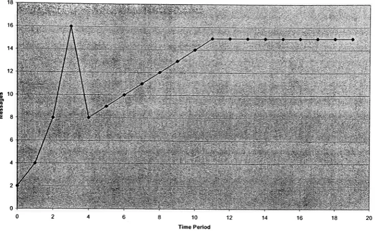
each. This isaformofcompressingrepresentativedata intoa singlefinalaggregated result.Figure 3shows a simplified network with an establishedhierarchy. Weconsider a network
tobeorganizedinatree
topology
forreasonsdiscussed later inthis thesis. Itcanbeseenthat,ifnoaggregationis performed,therewillbeatotalof18transmissionsassumingallleafnodes and onlytheleafnodes respondto thequery. Shouldtheintermediatenodesalsohave datato report, therewillbe 21 transmissions. Ifresponsesfromtheleafnodes couldbecombined intoa single response at eachintermediatenodetherewouldonly be 12transmissions torespondto thesame query.
Non-aggregated responses, 9 transmissions
si\A\A*
Individual responses, 9 transmissions
Figure 3: SimpleNetworkQuery Response,No Aggregation
Though ithas beenproventhatdataaggregation can saveenergy inwireless sensornetworks,
research issues such as where and when to perform the aggregation still exist [5]. Network designersrequire,
first,
an algorithmthatcan choose an optimallocation inthenetworktopologytoperformdataaggregation.
Some aggregation schemes that have been proposed are shortest path tree
(SPT),
centernearestsource
(CNS),
andgreedy incrementaltree(GIT) [26]
[43]. SPT isthesimplest ofthese.Each messageis routed to the sink viatheshortest path. Data is aggregated opportunistically
aggregationrequires the most overhead tosetupout ofthese threeaggregation schemes [26]. SimilartoDjikstra'slink-state routingalgorithm,aggregation pointsare chosen
iteratively
beforeaggregationbegins. Thisrequiresknowledgeoftheentire network andlinkcosts. Though it is notnecessarilya priori
knowledge,
itcouldbeconsideredsuch,sincetheaggregationtreemust becreatedindependently
fromtheroutingtopology[22].2.1 Data Aggregation
Timing
Most researchers agree that data aggregation is a useful technique for reducing energy
consumption in wireless sensor networks
[26]
[41].However,
how to determine appropriate aggregationtiming
characteristics remains alargely
unexploredfield.Inalargescale
WSN,
theremay bea significantdelay
betweenwhen an eventissensed(oraquery is answered) and when thedata reachesthe sink. For maximum energysavings, each aggregating sensor should be able to transmit all data received from all ofits children at one time. Thiscouldleadtoan even larger
delay
betweenwhen thedataoriginates and when itisfinally
reported, as each aggregating node may have to pause before sending a report to its parentDepending
onthepriorityofenergy savings vs. maximumlatency,
it may make more senseforan aggregatortowaitforall, some,oronlythefirstofitschildrentorespond.Forexample, Figure 4 shows a network with a potential timingproblem. In the case in
which leaf nodes and only leaf nodes respond to a query, if Node B wishes to aggregate responses from itschildren, it will be facedwith adecision of whethertowaitfortheslower responsefrom Node Corto transmit theresponsefrom Node D firstand sendC'sresponselater. Thisassumesthateachtransmissionover a wirelesslinktakesexactlythesame amount oftime. Ifthisisnotthe case, thetimingproblembecomesmore complicated andless deterministic.
Level 3 B39 Sink
Level2
Level 1
Level 0
Figure4: Unbalanced NetworkwithPotentialTimingProblem
aggregation, but stopshort ofspecifyingdetails forany specific implementation. Others have
proposeddetailed aggregation schemes intendedtobeused withDirected
Diffusion,
including
"Greedy
Aggregation"[41]
and CLUDDA [7].However,
none ofthese address the issue oftiming
controlbetween differentlevelsof sensors. Mostaggregation schemesfocusonfinding
an optimal node at which to aggregatedata,
simply mentioningthat aggregationis performedthereand oftenassuming intheircalculationsthatall responses received are aggregated before
being
propagated.Based onthe
timing
modelsdescribedby
SolisandObraczka in[41],
existingperiodicdataaggregation protocols canbeclassified into three categories,namely:periodicsimple,periodic
per-hop,and periodicper-hopadjusted. Periodicsimpleaggregation works
by having
each node wait a pre-defined period oftime,aggregate alldata itemsreceived,and send out a single packetcontaining the result. Aggregation mechanisms in theperiodicper-hop category have nodes
sendtheaggregated packet as soon as
they
hearfromalltheirchildren.Excessively
latereports are dropped as inperiodic simple.Finally,
periodicper-hop adjusted schemes use the samebasicprinciple ofperiodicper-hop butschedule a node's timeoutbased on itsposition in the
distribution tree (rooted at the information sink and spanning all reporting and intermediate
nodes). The aggregation scheme proposed
by
this thesis fallswithin this category, and, whencomparedto otherexistingperiodicper-hopadjustedalgorithms,presentsbenefitssuch as not
requiringclock synchronization amongnodes andminimizingthe timeoutschedulingoverhead.
Thedetailswillbe discussed laterinthe thesis.
WereferagaintoFigure3. Nodesa,
b,
and c are child nodes.They
transmittheirresponsesatthe end oftheirrespectivetimeouts, whichare notnecessarilysynchronized.
Theoretically,
sincetheyare allleafnodes,theycouldtransmit earlier,butthisexampleholdsfornodesinternal
to the treeas well. Node d isan aggregator and the parent oftheotherthree nodes. It will
ideally
receive responsesfromall ofitschildren,butwilltimeout after somelengthoftime.Figure 5 shows the response schedule forrepresentative periodic simple, periodicper-hop,
and periodicper-hopadjustedschemes astheywouldapplyto the treeshownin Figure 3. Two
examplesare givenforeachscheme;child nodesrespond atthesametimeinallthreeschemesin
each example. Theshaded sectionsindicatetimebefore theaggregator'stimeout that itwould
nothavetowaitbecause itschildrenhaveall responded. Inthesecondexample,not all children
Nodea
II
II
Periodic b
II
II
Simple c
II
II
d
1
1
1'
1
Nodea
~r
I
I- ~T~
Periodic b
l
r
IPer-hop c T~
~i
I
T~
d
i
ii
i
i; .Nodea
~Tl
~n
Periodic b
~i
n
Per-hop c T~
n
Adjusted $ 1i.^^ir
U
Figure 5: Response Times for Several Aggregation Schemes
Periodicsimpleisthesimplestto
implement,
butexhibitsthemaximumlatency
inall cases.Periodic per-hopreducesthe
latency
in thefirstexample, as expected. Inthesecondexample,both oftheseschemes must
drop
nodeb's response(or wait until thenextreporting period).Finally,
periodicper-hopadjusted performsideally
in bothexamples. Becausethechildren areconfigured with a shortertimeout, this scheme can aggregate all responses before its timeout
eveninthesecond example.
Directed Diffusion's communication paradigm is basedon information sinks
broadcasting
requests, orinterests,forrelevantdata. Nodeswhohaverelevant informationrespond to these
requests anddatapathsareformed alongthereturn route. "Better"routes aredetermined
by
thenumberand qualityof responses that are sent along it. Data is aggregated opportunistically;
wheneveridenticalresponses orqueries meet at a nodeonlyoneisretransmitted. Though every
node canpotentiallyperformaggregation,nodesintheshortest pathfrom informationsourcesto
thesinks are responsibleformostoftheenergysavings[22].
In periodic simple aggregation protocols, all nodes wait a pre-defined amount of time,
aggregate all thedatareceived withinthat period, and send out a single packet[41]. Directed
Diffusionfalls intothis categoryonlywhen all nodeshaverelevantdatato send. In this case,
reinforcementqueriesfromthesinkspecifythedesiredresponse rate. Notethat nodesare not
necessarilysynchronized when
"clocking
out"data. Thoughseveralcloselygrouped nodesmay
respond at an identical rateof once perminute, these individualresponses may not go out at
TAG
[28],
orTiny
AGreggation,
is a good example of a periodic per-hop adjustedaggregation mechanism(see Figure 5). TAG uses aggregationas queries are processed within thenetwork. Somequeries in TAGrequest reportstobesentfromsensors periodically. Inthis
case,TAG
intelligently
subdividesthedatacollection"epoch"
intosmallerslots. Eachslotisthe
epoch length divided
by
D,
the depth ofthe tree.Following
per-hop adjusted aggregationoperation, slots are assigned to nodes in
decreasing
order,D, D-l, D-2,
..., as the query propagatesthrough thenetwork. Thisscheme requiresknowledgeofthenetworktopologyandtime synchronizationbetween nodes,but allows nodes topowerdown when notscheduled to
transmit or receive. Our proposed aggregation scheme is not affected
by
the potential sleepschedule and ourMAC layerscheme,discussed
later,
takesfulladvantage ofit.In additiontoTAG
[28],
another well-received aggregation schemeis AIDA [15]. Thoughboth ofthese schemes suggest several potentially energy-saving
ideas,
they focus on disjointaspects of aggregation. TAG'smainfocus ison an efficientquerying languagethatisconducive
to aggregation,but is mainlyan application-level optimization.
AIDA,
ontheotherhand,
insertsa newlayer intotheprotocol stackthatinterprets and repackagesdataneartheMAC
layer,
but doesnot considerdynamictimingparametersbased on application-level requirements. Bothoftheseframeworksare usefulforreducing energyconsumptionin WSNsand are compatible with
ourtimingprotocol,but donotadequatelyaddresstheissuesthatwehopetosolve. Theconcept of
"cascading
timeouts,"
where nodes would waitfora period oftime
directly
related to their depth in the aggregation tree, was recently proposed in[41] by
Solis and Obraczka. Though this is a potentially useful optimization, its main shortcoming is that itrequires significantadditionaldatatobetransferred
during
thesetupperiod. Ourtimingcontrolscheme requires minimal overhead, but is flexible enough to allow expansion for later optimizations.
Wenextdiscussthestate-of-the-artinthearea of cross-layer
design;
thesecondfocusofthis thesis.3
Cross-Layer Design
3.
1
Traditional
Network Model
-OSI Stack
The
following
isabriefoverview of what we considerthe traditionalnetworkprogrammingmodel, as defined
by
the International Standards Organization. A moredetailed description isTable 1
Layer Name Function
Layer 7 Application User interface
Layer 6 Presentation Formatconversionandinterfaceto theapplicationlayer Layer 5 Session Maintainsmultiplelow-levelconnections asa singleentity
for logicalorganizationintheapplicationlayer. Layer 4 Transport End-to-endreliability
Layer 3 Network
Routing
Layer 2 Data-link
(MAC)
Neighbor-to-neighborcommunicationLayer 1 Physical Communicationacrossthephysical medium
(wire,
fiber optic, radio,etc.)Ofthese, layers 5 and6arerarelyconsideredseparately insensor networks. Theoperation oftheapplicationlayer is dictated
by
thepurposeofthesensornetwork. Acommon view ofthesensor networkisas adatabase. Inthis case, theapplicationbecomesthequery interpreterand little isrequired ofthepresentation or session
layers,
sotheymay be practicallyeliminated.Thetransport layer is responsiblemainly for end-to-end reliability. This is a specialized requirementin sensor networksbecausetheirusagedeviates froman Internet-type host-to-host communication paradigm. Queriesmust reachmost,ifnotall, targetsensors and responses must be returned, perhapsanonymously, to the sink.
Assuring
that each query and each responsedefinitively
reachesits destination is infeasibleonthisscale. Becauseoftheredundancyofdata andlargenumber ofsensors, thefunctionality
ofthe transportlayer is effectivelyaccomplishedby
therouting layer. Queriesand responses shouldberouted with somereliability, whichmay wellbe lessthan100%. Lostmessages and messages with errorsmay be ignored.There have been a number of proposed optimizationsfor boththeroutingandMAC
layers,
howevermost all oftheresearchconsiders themseparately[17] [21]
[48].Only
recently have researchers begun to classify the problem ofofficially combining functions from these two layers. Sofar,
research indicates that significant energy can besavedby
eliminating at leastsome oftheboundaries inthetraditionalmodel[36].
Thisisnotsimply a matterof computation and encapsulationthat must occurbetweentwo layers.
Obviously,
fewer interfaces betweenlayers will reduce code complexity. Inaddition, information traditionally not available to the MAC orRouting
layer may allow them toMAC and routing layers is of particular interest. We will analyze the benefits ofrelating
protocolsfromthese twolayersinChapter4.
3.2
Optimized MAC-layer
design based
onrouting information
Inregardto traditionalMAC layer protocols, TDMAcan make use ofinactivetimeslotsto
put some sensors to sleep and reduce energy use.
However,
were the sleep schedulingmechanism apprised of whether or notthe sensor wastobeusedto route messages
during
thenexttime slot, itcould opt notto turnon thesensorforthat slot and
thereby
save even moreenergy. This isa majorissue for low datarate sensornetworks,where nodesmay berequiredto
awake from sleep mode farmore often than they are actuallyused to route data queries and
replies.
There exist several customizedMAC protocols, specifically designed forsensornetworks,
such asSensor MAC
(S-MAC)
[48]. Though itshows a reductionin energyconsumption,since it is stillroute-oblivious, itwastesenergy since sleepperiods are not coordinated withroutingfunctions.
Even customized MAC protocols such as S-MAC cannot completely account for the
additionalenergyconsumeddueto thefactthatthesehighly-optimized routingprotocolsdonot
consider the operation ofthe MAC layer. As shown in
[36]
and[50],
energy-efficiencyofnetworks using these routing protocols can be improved
by
using a "route-aware" MACprotocol. Thisreducestheseparationbetweentheoperation oftheMAC layerandrouting layer. We holdthat thisisa usefultechniquefor reducing energyconsumption and examinetheissue in
detail.
Ourprotocol will take thisconcept onestep further
by
combiningrelevantfunctionsofthreemajortraditionalnetworking
layers;
theMAClayer,
theroutinglayer,
andtheapplication layer. The authors of[50]
analyze the benefits of different layers'common optimizations as
implemented in wireless sensornetworks. Theirresults are discussed in detail in Chapter 4.
They
arguethat cross-layerdesign isa goodidea,
specifically becausetheoptimizations inone layer may counteract those in another. This is shownby
the simple example of a routingalgorithm that discovers the shortest route from sensors that sense an event to the data sink. When an event occurs, perhaps after a period of complete
inactivity
on the wireless channel,these multiple sensors all simultaneously report the event, causing a sudden escalation of
Zhang
andCheng
proposetheirownMACschemeaimedtoavoid contentioninthepresenceof
bursty
data transmissionsand routes pronetohotspotsthatare commonin WSNs. Few detailsaregiven,butthemaindrawbackisthattheyspecify theuse of out-of-band signaling. S-MAC avoidsthisrequirementandthe twoideasshouldbe
functionally
compatible.In
[33],
the authors analyze the idea ofusing MAC-layer information to create optimizedclusters, usually the responsibility ofthe routing layer. An interrogator in the MAC layer realizesitsrole and usesthiscriteriontobecomea clusterheadin therouting layer. Simulations showthat this isafeasibleapproachfor creating clusters. All packetprocessingoccurs inthe
MAC
layer,
which essentially combines the routing and MAC layers. This allows nodes todynamically
decide uponthenumber of neighborstocommunicate with(an importantcriterion in theirsystem) based on overheard MAC layer frames.Logically,
one expectsthat creatingclustersbasedintheMAC layerismore efficientthancreatingacompletelyconnectednetwork, theneliminatingsome oftheselinks basedon aroutingprotocol. Thisassumesthattheclusters formed are comparablein efficiencyto thosethatwouldbe formed
by
usingadedicated routing layer clusteringalgorithm. Performanceoftheproposed protocolisshown,buttheauthorsstopshortofany directcomparisons.
4
Summary
Wireless sensor networks are a relatively new area of research. As the technology has
developed,
many issues have arisen that are unique to these networks. This is promptingresearch on efficient algorithms to organize the networks, how to spend the least amount of
energy to communicate
interesting
data,
and thedifferences ofWSNs that may requirea new networkprogrammingmodel.After studyingthestate-of-the-artinthesetwo areas,we estimatedthatwecould supplement
and extendthework of others with our newideas on
Timing
Control in Data Aggregationand Cross-layer design. Weproposeto leveragethecurrentresearchand analyze several potentialoptimizationsinthese areas. In the
following
chapters we will examine adetailedexample ofChapter
3
A
Novel
Timing
Control for
Optimal
Data
Aggregation
We now present the first focus of this thesis. We will analyze the issue of timing
requirements when aggregating data in WSNs and propose a protocol thatprovides increased lifetime and performance. We then propose several new timing control algorithms that are
compatible with our protocol and attempt to
dynamically
update data aggregation timing parametersto extend system lifetime. These performance ofthe algorithms described inthischapter are evaluatedlaterinthis thesis.
Chapter organization: In this chapter, we first describe the problem to be addressed in
Section
1,
andthenin Section 2we enumerate some assumptionsnecessary forournetworkingtopology setup. In Section 3 we provide detailed descriptions of multiple versions of our
aggregation timing control scheme and in Section 4 we perform a theoretical analysis ofits potentialenergysavings.
Finally,
in Section5,
welistseveral example applications andhowouraggregation scheme canbeappliedinnetworks with
differing
priorities.1
Problem Statement
In orderto minimizeenergyconsumption, many networking schemes attemptto minimize
the amount ofdatatransmitted
by
using someform ofdata aggregation. This tradesoffdatafreshness forsavingsinenergy,becausereportsfromsensor nodesthatarrive at anaggregating
nodemay havetobe heldthereforsome period oftimebefore
being
reportedsothatadditionalreportsmayreachtheaggregatorfromslower nodes. This isa separateissue fromtheprocessing
timeneededtoaggregatedata frommultiplesources.
For
instance,
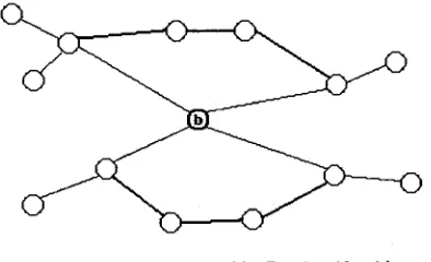
in Figure6,
nodeBwillreceivedatafromnodeDbefore itreceivesdata fromnodeC becausenodeCmust waittoreceivedata from bothnodesEand
F,
assumingthatallleaf nodes reportdataand aperfectMAC layer. Inthis example,should nodeBwaittohear from nodeCorpromptly forward D'smessageassoonasit isreceived?There are a numberofissues that affect this
decision,
such as whetherB is aware ofthewillhavetowaitfor exactlythe
delay
incurredby
a singlehop
transmission, it mayopttowait for C's response(based on knowledgeofthemaximum response latency).Otherwise,
it may havetowait until atimerexpires. Alsonotethatifthenetwork wereanylarger,
forexampleifnodeE hadchildrenGand
H,
we would encounter a similartimingproblem,butwith adifferent solution sinceE isfartheraway fromthesink.Sink
Level 1
Level 0
Figure6: Simple NetworkwithPotentialAggregationTimingProblem
Inthisthesis,we proposetouse a novel intelligenttimerand somehigh-level knowledgeof
the networktoimplementan efficient aggregation timingcontrol scheme. Basedon a node's
position inthe network,itwillknow how
long
itcan waitforreportsfrom itschildren withoutexceedingthemaximum
latency
for itsown reporttoitsparent node. Itmustbepossibleforthe sinktoindicatethroughthenetworkthehighestacceptablelatency
andthenodesthroughout the network musthavesomeideaofthenetworktopology.We assume a reasonably linear relationship betweenthenumber of messages and the time
period. It has beenshown
by
Yuan, Krishnamurthy,
andTripathi in[49]
that,toapoint, thisis true. This is discussed later in this chapter. With this assumption and the knowledge listedabove, the sink and sensors will be able to calculate maximum timeouts that satisfy the application-leveltimingrequirements.
As discussed in Chapter
2,
timing models can beclassified into three categories, namely:periodicsimple,periodicper-hop,and periodic per-hopadjusted. Forthepurposes oftimingin
our aggregation model, we propose an efficient periodic per-hop adjusted scheme whereby a
node,
being
aware of its distance in hops from the sink, can reduce the timeout period proportionallybefore retransmittingtherequest.It is not necessary for a node to know the number oflevels below it in the tree as the
calculations arehandled
by
thesink. Thisis incontrasttoschemes wherethesink mustdiscover the networktopology, thenpropagate this informationtoall nodesin thenetwork. Each nodespecifies too short of anaggregationperiod aggregators somewhere above the leafnodes will
timeout and return alimitednumber of responses.
Only
localsynchronizationisrequired,asthewireless propagationtime isassumedto benegligible andis accountedfor
by
thedynamically
updated globaltimeout.
Thescheme proposedinthischapter canbeachievedsolely intherouting layeranddoesnot
interfere with any potential sleepschedule enforced
by
theMAClayer,
which is discussed inChapter 4. In thenext section we listanddiscuss some assumptions relevanttotourproposed
aggregation
timing
mechanisms.2
Assumptions
2.1
Topology
assumption:Cluster-Tree
architectureIntermsofWSNtopologiesforthepurpose of optimaldataaggregation,we proposetomake
use ofbothmethods(i.e.atreeconsistingofcluster-heads)
[20]
sothatgroups of sensor nodeswill combinetheirreports atthelowest
level,
thenreportsmaycontinuetobeaggregated astheypassupthe aggregationtree[17]. Wearguethat thisisapromising routing implementation in
termsofscalabilityand overall energyefficiency. Sinceeach cluster-headfirstperforms local
aggregationin itsclusterbefore
forwarding
datatothenextcluster-head, this thesiswillfocusonthe data aggregation issue in the entire tree(i.e. between cluster-heads instead ofinside each
cluster).
Consider Figure 7. In this
figure,
each circle can represent a sensor node. In thefigure,
groups oftwoorthreesensor nodes atlevel iare groupedtogetherunderthecontrol of another
node atleveli+\. Nodesatlevel/areleaves inthe treeandfunction onlyas sensors. Thevast
majorityof nodesinthenetworkfall intothiscategory. Nodesatlevelj+1 and
higher,
uptotheroot ofthetree,wouldbeconsidered clusterheads. Thoughtheyare still sensor nodes andmay
have
individually
senseddatatoreturnto the sink,they
arefewenoughinnumberthatour mainconcern with them is how much data they forward.
Alternatively,
thecircles at level 0couldeasily beentireclusters. Membersoftheseclusters communicateto therest ofthenetwork via
the organization will be the same. In
fact,
ahierarchy
of some sortis practically guaranteedwhenclustering[13].
In this thesis, we usethe relative
terminology
interchangeably;
each circle in thediagrammay bethoughtof as anode,acluster,or a clusterhead andthecircle atthehighest levelwillbe
referredtoas eithertheclusterhead orthesink,
depending
onthecontext.Level2,
Sink/Ctusterhead
Level 1, Clusterhead/Node
Level0, Ouster/Leaf Node
Figure7: SimpleTreeNetwork
OnthedeterminationofCluster Size:
Givenafieldof size m
by
nanddisregarding
theeffect of clusteroverlap,onehasa choice astohow largetomaketheclusters. Weconsidertheradius of a clustertober,ineitherdistance
orthenumber ofhops2. For simplicity,rshouldexactlydividemandn.
Thetotalarea covered
by
theclustersisthesum oftheareas coveredby
each oftheclusters.Thetotalnumber of clustersisthenumber of clustersthatfitintothefield
horizontally
times thenumber of clusters that fit into the field vertically. These qualities are expressed
by
thefollowing
formula:x r r cov erage=
which simplifiesto
cov erage=
(mx
n)n,showingthatrdoesnotaffectthe totalradio coverage ofthenetwork3.
Though mathematicallythecluster radiusdoesnot affect coverage ofthe
field,
thisdoesnotrepresenttheenergy efficiencyofthenetwork. Withalargercluster
diameter,
clusterheads will have to transmit fartherto reach each other, but the treeof clusterheads will be simpler. A2
Inanevenlydistributed fieldofsensors, thesewillbeproportionalunits ofmeasure. 3
Thisapproximationholds ifsensors'
simplertree leads to more energy-efficienttopology maintenance at this level. Also with an
increasing
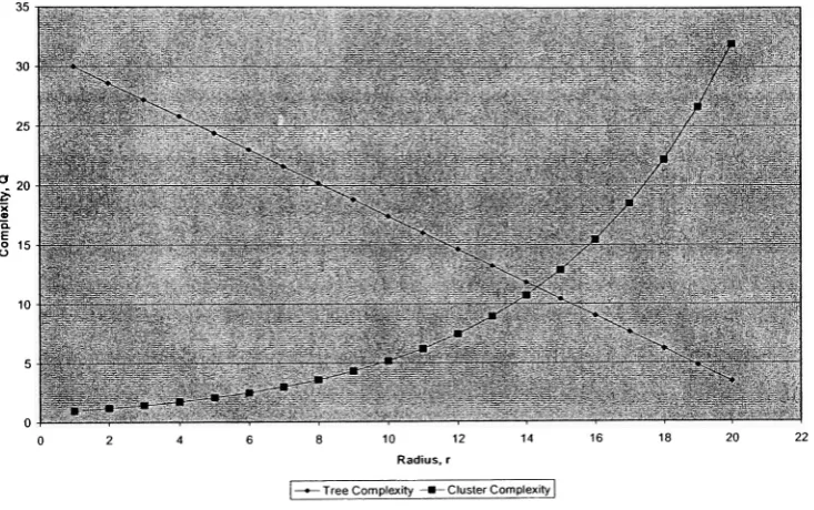
r,maintenance and communication costsforeach cluster willbe increasing.There isabalancetobestruckbetweencluster size andtreesize. Thelargertheclustersare, the smallerthe tree of clusterheads may be and vice versa. Theradius of a cluster, r, is the
independent variable in this case. The dependent variable is the efficiency ofthe network topology. Thiscanbevisualized
by
thefollowing
figure:Cluster Sizevs.NetworkComplexity
| *
TreeComplexity
--ClusterComplexity|
Figure8: Tree Sizevs.ClusterComplexity
Theoptimumbalance may be calculated offline and isnotpartof our protocol.
However,
thisplotdoesshowthat thereexists some optimal point. Asuboptimal choiceforrwill resultin
some amount of
inefficiency,
soit isnot enoughtousesolelyatreetopologyor a single cluster.Asmentioned, we consider anetworkconsistingofa treeofclusters. Witha given number
ofnodes, largerclusters allow asimplertreeandvice versa.
Assuming
clusters arecircular, thenumberof nodesina cluster andthe complexityof eachincreasesexponentiallywithr. Thetree
[image:28.546.104.471.181.411.2]showthecomplexityofcommunicationwithinthe tree to change
linearly
with r[13]. This isasimplifiedexample, butshowsthat thereissomebalanceof organizationalefficiency betweena
network with a single cluster and a network inwhich each sensor nodeis a nodeinatree. The
optimumbalancemay becalculated offline andisnot part of our protocol. Asuboptimal choice
forrwill resultinsome amount of
inefficiency,
soit isnot enoughtousesolelyatreetopologyor a single cluster.
2.2 Other Assumptions:
Animportantnote aboutWSNs ingeneralisthattheyaredata-centric [16]. Thismeansthat
dataisrequested and returnedto thesinkbasedonitsrelevanceto the query,ratherthanbecause
it was requested from a specific node. For our aggregation scheme we assume queries are
definitive fornameddata. This isa minorassumption,and our protocolreallyonlyrequires that
onequerycanbe differentiated fromanother,whichisa reasonable requirement.
Thismeans thatend-to-end addressingwill notbeused, though
hop-to-hop
addressingwillbe. Even in WSNsthatuseclustering, thereis usuallya concept oflocal addressing (withinthe
cluster)
[25]
[26]. Messagesarebroadcasttoall other nodes within radio communication range.The receiving node mustbe able to recognizeat least the typeof message in orderto decide
whethertointerpretthedatawithin,forwardthemessage,orignorethemessage.
A minor distinction to be made is the communication model. Commensurate with the
wireless nature of
WSNs,
messagesare assumedtobe broadcasttoall nodes withinradio range.Thisnecessitatestheuse of either
hop-to-hop
addressingor messageIDstoavoidloops. Despitethephysical
implementations,
conceptually messages are unicast from node to node in that aparent can send a messagetoitschild and viceversa,with other nodesthatoverhearthemessage
discarding
it. Some WSNschemesrelyon gossiping topropagate messages[16]. This is notrequiredforoperation ofanyoftheaggregationschemesdiscussed inthis thesis.
The final assumption, which is necessary to this
discussion,
is that meaningful dataaggregation mustbeabletobeperformed. That
is,
datageneratedby
thesensornodes mustbeable tobe combined in some waythat shortens the total message,while retainingthe original
information. The specific aggregation function is beyond the scope ofthis thesis, but this
A query that asks forthe maximum value sensed is an ideal candidate for aggregation
becauseanynumber of messages canbe easilycombinedintoa single value attheaggregator. A
query fortheaverage over afield is slightlymore complicated inthat thenumberof responses
mustbe communicatedtocalculatethe average, butthefinal message will stillbeshorterthan
multipleindividualresponses.
Finally,
aquery forall values sensed wouldnotbea candidateforaggregationbecauseeach value mustbeappendedtothemessage andthefinalmessage willbe
proportionalinlengthto thenumber of sensorsresponding.
3
Proposed
Time
Synchronization
Algorithm
An important research topic necessary to the idea ofdata aggregation is timing control.
Figure 7 represents a simple network organizedintoa tree topology. Ina realistic WSN there
would be many more nodes and potentially a much deepertree. With deepertrees, timingis
even moreimportant [26].
Aggregationtradesoff
latency
for energysavings. Because aggregatingsensorshavetowaitfor data fromtheirchildrentoarrive, therewillnecessarily besomeincrease inthe timeittakes
them to respondto queries. As illustrated in Figure
7,
a node atlevel 2 would need towaitlongerthannodes atlevel 1 inordertosend aggregateddatatoitsparent node. There isadesign
tradeoffin the maximum amount oftime to wait. Ifan aggregating node waits too
long,
theresultsofthequery maynotbetime-relevant. This is especiallytrueinsituations inwhichthe
datasinkmaywantinitialresultsimmediately.
Latency
tradeoffsareapplication-specific,soweassumethat theapplication
(running
onthesink)can choosetheoptimaltargetlatency.Inmost aggregationschemes, latereports aresimply discarded
[26]
[49]. Wefeel that thisdecisionshould be upto theapplication.
Depending
ontherequirements oftheapplication, itmaymake more sensetoacceptlateresponses. Notethat thisisa separateissue from usingthe
number oflateresponses tocalculatetheaggregation period. The ability fortheapplicationto
dictatetheaggregation action canbeadded
by
a singleflag
accompanying dataqueries. This isdiscussed in detail in Section 3.4.
Amajorconclusiondrawn
by
theauthorsof[49]
isthat theaggregationtree(not necessarilythecommunicationtree)plays thelargestrole in theefficiencyoftheaggregation. While it is
true that theaggregationtopologyis
important,
it isnot enoughtodependon anidealtree. Stepsto performance. Ourprotocol aims to do this
by informing
interested nodes ofthe(limited)
network
topology
inthemostenergy-efficientmanner.Using
thisinformation,
thedatasink canmakeintelligent decisionsaboutthe tradeoffsbetweendata
latency
andpotentialenergysavings.Our proposed aggregation
timing
control protocol, as do many others, makes use of aseparatesetupphasetodistribute parametersnecessary foraggregation. This istypical of, and
compatiblewith,mostdynamic routingandMACprotocols. The setupphasetakessomefinite
amount oftime and is followed
by
a much longer data collection period. These phases arescheduledtooccur periodically. The
frequency
with which theyoccuris discussed in Section3.2. The
following
figureshowsthegeneral scaleinwhich our protocol will operate.Control Parameter SetupPhase
3=
]
Repeat
DataCollection Phase
Figure 9: Setupvs.DataCollectionPhases
3.1.1
Setup
phase1. Sink broadcasts "depth
request."
Therequestispropagateddownthrough thenetwork
similarlytoa simpledataquery.
2. Messagereachesbottomandisreturnedbackup. Eachnode returns withits
hop
count,starting from leavesatlevel 0. Theparents ofthesenodes realizethattheyare atlevel 1and
passthisinformation back up thetree. Thiscontinues untilthesink retrievesinformation
abouttheentiretree. Eachnode propagatesthedepthrequesttoitschildren and each node
returns an answertoitsparent,sothisisaccomplished withcomplexity<9(depth).
Inordertosaveenergy
during
thissetupphase,somelevelof aggregationmay beperformedatthisstep. Possibilitiesvaryfrom
transmitting
informationthatcompletely describesthenetworktocommunicating onlythemaximumdepthofthe tree. Theseoptions arediscussed
more
fully
in Section 3.4.3.
Finally,
thesinkwillcalculate andtransmitan appropriate valuefor T basedonthedepthofthetree,themaximum
latency,
andtheoptimal number ofresponses,whichisassumedtobeAfter performing thisexchange,eachaggregatingnode,
including
thesink, should haveallknowledgenecessary forittocalculate an appropriatetimeoutperiod.
Depending
onthelevelofaggregation performedin step
2,
nodesmay beawareofhow balancedor unbalancedthetreeis,
or parent nodesmay beaware oftheentire aggregationtreebelowtheirpositions.
3.1.2
Data
collection phase1. Thesinktransmitsa new
querywith an updatedtimeoutperiod. This doesnot requireany
timesynchronizationbecausethesensors and aggregatorsjustmaintaintheprevious value
until notified. Aggregatorsthatreceivethequeryreduceituniformlybefore propagatingthe
queryasdescribed inSection3.5.
2. Eachaggregator replies withthenumber of replies received
(average,
perquery)anditsdepth inthe tree. Notethatan aggregatorthatistheparentof anotheraggregatingnode will
sumitstotalnumber received
(Nrec)
withitschild's report. Aggregators may optionallyreportthenumber and
timing
oflatereports. Weterm theseNiate
andTiate
anddiscusstheminthe
following
section.3. Thesink will send out an updated
Tn+i
toallaggregators,basedontheFSM. cisa parameterchosen
by
theapplicationinthesinkthatrelatesNop,
toTopt.3.1.3 Optimization
In order to get the most accurate view ofthe network, aggregators may also report the
number and/ortimeoflatereports. Thiswouldallowthe sink,ifpowerfulenough,tochoose an
appropriate aggregation period even moreintelligently.
For example, the "maximum latency" ofthe application may be provided along with a
flexibility
factor,
flex and its associated weight,flexing*. If the sink does not receive asatisfactory number of responses, it may calculate the benefit of
increasing
the aggregationperiod.
Disregarding
networkfluctuations,
thiscanbe doneby
simply countingthenumber ofnodes whoseadditionallatenesseswere reported tobe lessthantheminimum incrementofthe
aggregationperiod,T.
This number caneasily beweighted and compared to our application-levelparameters,flex
3.2
Control
Parameter
Refresh Rate
There isa concept of adata-collectionround. Thisroundmay includemultiple requests for
similar ordissimilar
data,
but uses thesame parameters fortiming, etc.forthedurationoftheround. At the end of a round, the performance experienced is evaluated and parameters are
chosenforthenext round.
As mentioned, the Masternodes, aggregators, or"clusterheads" are
likely
ordinary sensornodes, tasked with additional responsibilities. Forthis reason,theMaster(or clusterhead) must
berotatedperiodicallytoprovide areasonablyeven loadon each sensor node
[17]
[40]. Thismay be done after each round, or after a specific numberof rounds. This leads to another
tradeoff in energy efficiency. If the network is reconfigured
frequently,
it will lead tounnecessaryoverheadintheformof control messages and calculations. Attheotherextreme,if
the network
topology
is chosen once and remains static, then a single node will bearresponsibility foran unfair amount oftimeand will
likely
die before itscluster members. Thisalsodecreasestheoverall usefulness ofthe network,since whenthisclusterhead
dies,
it maytakeirretrievable datawithit.
It iscommon practicetouse asetupphase where we communicate allthenecessarycontrol
packetsforthecreation ofthenetwork
[17]
[39]. Atthispoint we couldconceivably informtheaggregating nodes oftheirdepth inthe tree. This is theonly parameternecessary forabasic
aggregationtimingscheme. Anotheroptionistoembed certain control informationwithin each
datapackettransferred. Thisprovides moretimelyfeedbackonthestate ofthe system,butadds
overheadintheformofadditionaldata foreachtransmission.
Wefeelthatbothofthesemethods shouldbecombined. Asmentioned,it is necessarytouse
some sort ofsetupphasetocommunicatethetopologyoftheaggregation network. Thisis
likely
part ofthenetworksetupphaseanyway,andfor simplicitythisoverhead will notbeconsidered
in detail inthisthesis.
The onlyadditional informationthatmayneedtobepassedback upthetree
during
thedatacollection phaseisoptionalinformationsuch asthenumber of messages missed
by
an aggregatorduetoa shortaggregationperiod,or perhapsjustwhether or notanymessages were receivedlate
fromthe lastquery. Thisrequiresonlyafewadditionalbitsas part ofthedatamessagepackets,
3.3
Finite
State
Machine
Implementation
ofAlgorithm
Several finite state machines were developed forevaluation. Each aimed to maintain the
number of messages received as close as possible to the optimal number (determined
by
theapplication). In addition, itwasdesiredtoreachthispointasquicklyas possible. The
following
are variables usedinthesestate machines.
N0[),
Optimalnumber ofresponses; determinedby
theapplication.Nrec
Numberof responsesreceived; talliedby
theaggregators and reportedto thesinkT Maximumaggregationperiod,distributed
by
thesink L+Maximum
latency
(applicationlevel)
Tj
Maximumaggregation period(fora node atleveli)
n Theround;T iscalculated onceforeachround,whichisassumedtobe
long
enoughtocreate aheuristicwithout
becoming
stale.Topt
AggregationperiodthatsatisfiesNrec
=Nopt
c Aparameter chosen
by
theapplicationinthesinkthatrelatesNopttoTopt.Nia,c
Numberoflatepackets receivedby
aggregatorsTiaK
Timeunits whilewaiting for latepacketsD Depthofthe tree
K Levelof nodeiinthe tree.
? Differencebetween Tateachlevelofthe tree
If D is
known,
the sink can derivea maximumT;
for each level inthe tree, based onthemaximum
latency (L+)
oftheapplication:7)
=V-KAEquation1
Since the nodes know their own level in the tree, they can
individually
calculate theiraggregation periods, using the above formulaand ? ifavailable. Our protocol is capable of
distributing
this deltaas partofthecontrol message. Itwasfoundduring
simulationsthat thisparametercouldbeeliminated. Detailscanbe found in Chapter 5. Thoughtheremay besome
advantageusingavariable
?,
thereisatradeoffintheamount of controldatatransmitted. Thisissue isanalyzedinmoredetail in Section 3.5. Theempirical performance advantages ofusinga
deltaareleft for futureexperimentation.
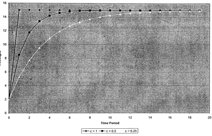
Thesimplestfinitestate machineshownbelowwas
initially
derived fromtheapproximationthat the number of responses received
by
the sink isdirectly
proportional to the aggregationperiod. Thisisa reasonableinitialassumptionsince,
logically,
alongerperiod will allow morefor choosing an aggregation period, and the amount of control data necessary.
Minimizing
complexityshouldbetheaim ofany algorithm, especiallywhenenergyconsumptionisa major
concern.
This initial assumption may prove to be naive,
depending
on MAC and physical layerperformance and even the traffic model, which is network- and application-specific. Ifthisis
found tobethecase
(experimentally),
our protocol can be easily modified to allow optimizedperformance. Evenwith anexampletrafficmodel as shownin
[38],
our protocol should performwell without modification as it still
dynamically
changes the aggregation period. The mostnotableshortcoming isthattheperiod willbereduced
linearly
oncetheoptimal pointisreached.Thiscanbeeasilymodifiedifthe traffic ismeasuredas shownin
[38],
insteadofthemodel webasedour protocol on.
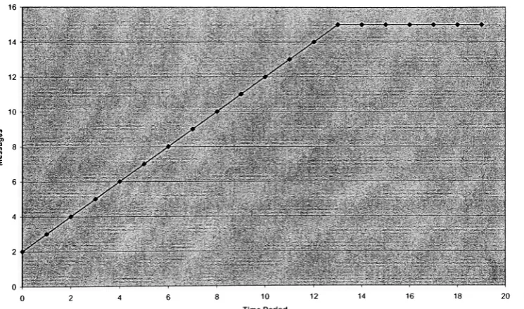
Thestate machinein Figure 10 isthesimplest. Ateach evaluation oftheaggregationperiod,
theoptimal number of messages received iscomparedto theactual number received. Ifthere
weretoofewmessagesreceived, theaggregation periodisincreased
by
one atomic unit. Ifmoremessages were received than were needed, the aggregation period is
linearly
decreased in asimilar manner. The amount of increase and decrease can be varied statically to suit the
application and network characteristics.
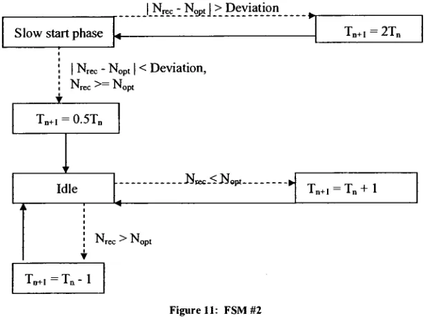
Thestate machinein Figure 1 1 requires amore complicatedformulatocalculateTn+i. Inthe
figure,
there are additional parameters used to calculate T. This figure also introduces theconcept of an acceptabledeviation. Thiscanlimitthenumberofunnecessarychangesin Tand
theattendantbroadcasts.
Thefinalstatemachine,shownin Figure
12,
doesnot make use ofthisacceptabledeviationparameter, but abstracts the multiplicand responsible for
increasing
anddecreasing
theaggregation periodinordertoreducethetimeneededtoprovideNopl.
Thetheoreticalperformance ofthesevarious state machi
![Figure 2thesink).themselves.sensorintermediate three shows a network that has been divided up into clusters [13]](https://thumb-us.123doks.com/thumbv2/123dok_us/122523.11877/12.546.84.458.314.549/figure-thesink-sensorintermediate-shows-network-divided-clusters.webp)