. PROCEEDINGS o/lhe
held march 1-3, 1955
in los angeles, california
and sponsored jointly by
• The Institute of
Radio Engineers
• The American Institute of
Electrical Engineers
l
~HE WESTERN Joint Computer Conference has greatly increased in size since the first meeting held in February of 1953. Membership actually has doubled. In 1955 there were 1,490 registrations as compared with 732 in 1953.The technical programs have always been designed to present material on both analog and digital machines. When possible, field trips to manufacturers and installations have been included in the Conference, as was done in 1955. This year 36 manufacturers exhibited products, as compared with 22 in 1953.
These statistics indicate increasing interest on the part of manufacturers, users, and potential users of the type of automatic data processing equipment discussed. The Conference has changed in character from a meeti~g of small groups of specialists discussing problems of mutual interest to large meetings involving people from many phases of engineering, management, business con-trol.
These Proceedings now are becoming of interest to an increasingly wider
.spec-trum of society.
WILLIAM L. MARTIN
Conference Manager
I
1955 WESTERN JOINT COMPUTER CONFERENCE
Proceedings of the
1955 Western Joint Computer Conference
Published by theINSTITUTE OF RADIO ENGINEERS
1 East 79th Street, New York 21, N. Y.
CONTENTS
Transfer-Function Synthesis with Computer Amplifiers and Passive Networks .... Page
· ... M. V. Mathews and W. W. Seifert 7
Simulation by Modeling ... N. L. Irvine and L. Davis 13
Ideal Transformers in Synthesis of Analog Computers ... . ... ... . R. H. MacNeal and G. D. McCann 16
A New Approach to Grounding in DC Analog Computers ... C. M. Edwards 23
The Need for Integration of Accounting Systems and the Design of Electronic Data-Processing Systems ... P. Kircher 26
Automatic Translation of Printed Code to Impulses Acceptable to Computing Equipment ... J. T. Davidson and R. L. Fortune 29
Data Collection as a By-Product of Normal Business Machine Operation ... .
· ... J. C. Taylor 34
Computers Challenge Engineering Education . . . F. C. Lindvall 41 An Optimiza'tion Concept for Business Data-Processing Equipment .. . D. R. Swanson 43
Data-Processor Requirements in Production and Inventory Control. ... . · ... H. T. Larson and A. Vazsonyi 48
Application of Data Processors in Production ... C. R. DeCarlo 61
The Integrated Use of Analog and Digital Computing Machines for Aircraft Dy-namic Load Problems ... . B. Mazelsky and R. F. O'Connell 66
A General Digital Computer Program for Static Stress Analysis ... . ... . . . .. . . .. . . P. H. Denke and I. V. Boldt 72
Aircraft Performance Studied on an Electronic Analog Computer ... . .... ... .. .. .. . L. B. Wadel and C. C. Wan 78
Coding a General-Purpose Digital Computer to Operate as a Differential Analyzer
· ... R. G. Selfridge 82
Introduction to Session on Learning Machines ... W. H. Ware 85
Generalization of Pattern Recognition in a Self-Organizing System ... . · ... W. A. Clark and B. G. Farley 86
Pattern Recognition and Modern Computers ... O. G. Selfridge 91
Programming Pattern Recognition ... G. P. Dinneen 94
The Chess Machine: An Example of Dealing with a Complex Task by Adaptation
· ... . A. Newell 101
Comments on Session on Learning Machines ... Pitts and Miller 108
A New Nondestructive Read for Magnetic Cores ... . · ... . R. Thorensen and W. R. Arsenault 111 The Electrographic Recording Technique ... . H. Epstein 116
An Electronic Digital Polynomial Root Extractor ... R. R. Johnson 119
A Set of Transistor Circuits for Asynchronous, Direct-Coupled Computers ... .
· ... R. A. K udlich 124
A Theorem on SPDT Switching Circuits ... . B. D. Rudin 129
Copyright, 1955-The Institute oj Radio Engineers, Inc.
All rights, including translation, are reserved by the IRE. Requests for republication privileges should be addressed to The Institute of Radio Engineers, 1 East 79th St., New York 21, N. Y.
1955 Western
Joint Computer Conference
OFFICERS
W. L. MARTIN, Chairman and Conference Manager Telecomputing Corp.
M.
J.
MENDELSON, Asst. Manager National Cash Register Co.W. F. GUNNING, Secretary International Telemeter Corp.
IRE
PROFESSIONAL SOCIETY REPRESENTATIVES
AlEE ACM
O. WHITBY Stanford Research Inst.
W. L. MARTIN Telecomputing Corp.
Exhibits
L. L. KILPATRICK, Ch. No. American Aviation, Inc.
B. A. CHIAPPINELLI ElectroData Corp.
P. KIRSCHER
Univ. of California, Los Angeles M. SHIOWITZ
National Cash Register Co.
G. D. MCCANN California Inst. of Tech.
R. R. BENNETT Ramo-Wooldridge Corp.
LOS ANGELES REPRESENTATIVE
J.
SALZERMagnavox Research Lab.
COMMITTEES
Arrangements
D. H. LEHMER Univ. of California, Berkeley
J.
L. BARNESUniv. of California, Los Angeles
Finance
G. E. GOURRICH, Ch.
J.
TUPAC, Asso. Ch. R. R. BENNETT, Ch. Telecomputer Corp. The Rand Corp.E. PETRY
National Cash Register Co.
J.
SIEDMANNational Cash Register Co. R. SINGMAN
Remington-Rand Inc.
Program
G. D. MCCANN, Chairman California Inst. of Tech.
Ramo-Wooldridge Corp. D. W. BURBECK, Asso. Ch.
Ramo-Wooldridge Corp. R. J. BARRETT Ramo-Wooldridge Corp.
L. E. MCGAULEY Ramo-Wooldridge Corp.
R. R. BENNETT H. D. HUSKEY
W. H. WARE
O. W. WHITBY E. S. CALHOUN D. N. MACDONALD H. H. SARKISSIAN
W. B. HEBENSTREIT P. ARMER
Publicity
E.ToMASH, Chakman Remington-Rand Inc.
D. T. GREENWOOD
R. BEMER Lockheed Aircraft Corp.
L. W. CALI W. WADDELL E. WEISS
Hughes Aircraft Co. ElectroData Corp.
Publications
A.
J.
DOWLING, Chairman ElectroData Corp.Registration
J.
E. STONE, Chairman Components Sales Corp.B. L. ETTELSON
American Machine & Foundry Co.
Librascope, Inc.
Trips
C. D. BEHM, Chairman ElectroData Corp.
F. M. HOAR ElectroData Corp.
v.
R. MACKIE1955 WESTERN JOINT COMPUTER CONFERENCE
ATLAS PRECISION PRODUCTS CO. Philadelphia, Pennsylvania
BENSON-LEHNER CORP. Los Angeles, California
BECKMAN INSTRUMENTS, BERKELEY DIV. Richmond, California
BOWMAR INSTRUMENT CORP. Fort Wayne, Indiana
BRUSH ELECTRONICS CO. Cleveland, Ohio
COLEMAN ENGINEERING Co., INC. Los Angeles, California
COMPUTER CONTROL CO., INC. Wellesley, Massachusetts
COMPUTER ENGINEERING Asso-CIATES, INC.
Pasadena, California
CONSOLIDATED ENGINEERING CORP.
Pasadena, California
EECO PRODUCTION CO. Los Angeles, California
ELECTRO DATA CORP. Pasadena, California
Exhibitors
ELECTRONIC ASSOCIATES, INC. Long Branch, New Jersey
FERRANTI ELECTRIC, INC. New York, New York
FRIDEN CALCULATING MACHINE CO., INC.
Los. Angeles, California
G. M. GIANNINI & CO., INC. Pasadena, California
GOODYEAR AIRCRAFT Akron, Ohio
HUGHES AIRCRAFT CO. Culver City, California
INTERNATIONAL BUSINESS MA-CHINES CORP.
New York, New York
INTERNATION AL TELEMETER CORP.
Los Angeles, California
LIBRASCOPE, INC. Glendale, California
MAGNETIC RESEARCH CORP. EI Segundo, California
MARTIN MANN ASSOCIATES Los Angeles, California
G. E. MAXON SALES Culver City, California
F. L. MOSELEY CO. Pasadena, California
THE NATIONAL CASH REGISTER CO.
Hawthorne, California
NORTH AMERICAN AVIATION, INC. Los Angeles, California
POTTER INSTRUMENT CO. Great Neck, New York
]. B. REA CO., INC. Santa Monica, California
REMINGTON -RAND INC. New York, New York
C. B. RUSH AND ASSOCIATES Los Angeles, California
SOROBAN ENGINEERING, INC. Melbourne, Florida
SPRAGUE ELECTRIC CO. North Adams, Massachusetts
TELETYPE CORP. Chicago, Illinois
UNDERWOOD CORP. Electronic Computer Div. Long Island City, New York
WIANCKO ENGINEERING CO. Pasadena, California
TUTORIAL SESSIONS PANELS
Subject
Digital Devices and Applications to Science and Engineering
Panel Members
P. ARMER, Chairman The Rand Corporation W. F. BAUER
Ramo-Wooldridge Corp.
J.
P. NASH K. POWELL University of Illinois Babcock and WilcoxE. C. YOWELL National Cash Register Co.
SUbject
Analog Computers
Panel Members
D. T. GREENWOOD, Chairman Lockheed Aircraft Corp. W.
J.
DIXONComputer-Engineering Asso.
C. H. WILTS
N. L. IRVINE Aerojet-General Corp.
California Institute of Technology L. G. WALTERS
University of California, Los Angeles
O. H. NIELSON Stanford Business School
DISCUSSION SESSIONS PANELS
Subject
Digital Systems and Applications to Business
Panel Members
E. S. CALHOUN, Chairman Stanford Research Institute
R. D. DOTTS
Pacific Mutual Life Insurance Co.
Subject
Techniques of Handling Non-Uniform Length Data
Panel Members
H. H. SARKISSIAN, Chairman National Cash Register Co.
J.
A. BRUSTMAN R. W. MURPHEY G. E. GOURRICHTelecomputing Corp. Radio Corp. of America International Business Machines
Subject
Language and Communication, Common Language
Panel Members
D. N. MACDoNALD, Chairman ElectroData Corp.
R. H. WAGNER ElectroData Corp.
H. F. MITCHELL Remington Rand
D. W. PENDERY
International Business Machines W. A. KAUTZ
E. M. MCCORMICK Naval Ordnance Lab., Corona
L. W. CALKINS
1955 WESTERN JOINT COMPUTER CONFERENCE
7
Transfer-Function Synthesis with Computer
Amplifiers and Passive Networks
M.
v.
MATHEWSt
ANDw. w.
SEIFERTt
Summary-The study of dynamic systems on an analog computeroften involves the synthesis of complex transfer functions. Tech-niques from the field of network synthesis are combined with meth-ods used in electronic-differential-analyzer work to provide effective means for realizing these transfer functions with a minimum of computer equipment. The basic ideas of associating high-gain ampli-fiers and phase-inverting ampliampli-fiers with resistor-capacitor networks are applied in order to obtain three systematic methods for synthe-sizing transfer functions of various degrees of complexity. The meth-ods described are illustrated by an example.
INTRODUCTION
M
ANY analog-computer problems require the synthesis of complex transfer functions. Real-ization of these transfer functions with a mini-mum of computing equipment is a practical objective that can be achieved by the use of passive networks in combination with computer amplifiers.Procedures for realizing stable transfer functions with passive networks containing resistances, inductances, and capacitances have been described by Darlington,l Guillemin,2 and others, but in many instances these methods have practical limitations. A synthesis involv-ing inductors frequently is complicated by inherent losses and distributed capacitances. Furthermore, in-ductors, particularly when used at the low frequencies encountered in computers and control systems, tend to be large and expensive.
Highly versatile methods, which avoid the limitations inherent in passive-network synthesis, may be derived by associating active elements such as amplifiers with passive networks. The basic ideas of associating high-gain amplifiers and phase-inverting amplifiers with passive networks were developed from feedback-am-plifier theory3 and were discussed by Blackman, Bode, and Shannon in a classified report in 1946 and by Be-love4 in 1950. In the computer field, full advantage has not been taken of the potentialities of these methods because they have not been developed into a systematic synthesis procedure that uses computer amplifiers as the active elements.
This paper describes three systematic synthesis methods which are particularly adaptable to computer
t Massachusetts Institute of Technology, Cambridge, Mass.
1 S. Darlington, "Synthesis of reactance 4-poles which produce
prescribed insertion loss characteristics," Jour. Math. Phys., vol. 18, pp. 257-353; September, 1939.
2 E. A. Guillemin, "A Summary of Modern Methods of Network
Synthesis," Advances in Electronics, vol. III, Academic Press, Inc., New York, pp. 261-303; 1951.
3 H. W. Bode, "Network Analysis and Feedback Amplifier Design,"
D. Van Nostrand Co., Inc., New York, N. Y., pp. 226-248; 1945.
4 C. Belove, "Synthesis of Active Low-Frequency Networks,"
Navord Report No. 1491, Bureau of Ordnance, Washington, D. c.;
November, 1950.
applications. First, the well-known method that em-ploys one amplifier and a feedback network is presented in its general form. Next, an original 3-amplifier design that offers distinct advantages in the synthesis of com-plicated functions is described. The third method pre-sen ted is a generalized version of the basic technique used for the solution of differential equations on a differential analyzer. In this last scheme, the active elements are integrators rather than amplifiers.
The computer amplifiers utilized in the synthesis procedures are assumed to be ideal amplifiers which draw zero input current, have zero output impedance, and provide any desired real gain. The assumption of a perfect amplifier is valid in the frequency range from direct current through the audio spectrum because, for these frequencies, computer amplifiers have been per-fected to such a degree that their deviations from the ideal are as small as the parasitic errors in resistors and capacitors.
SYNTHESIS USING ONE FEEDBACK AMPLIFIER
In electronic differential analyzers, integration is performed by associating a simple rc network with a high-gain amplifier, as shown in Fig. 1. If an ideal
am-Fig. 1-Block diagram for integrator used in electronic differential analyzers.
plifier with infinite gain is assumed, then analysis of the circuit yields for the ouput voltage
eo
= -Gc
f.'
eidt.+ Eo),
(1)where Eo is the value of the voltage across the capacitor at t
=
O. These same simplifications give for the transfer function of this circuiteo 1
(2)
- - - ,
RCs
where s is the complex-frequency variable.
the analysis of Fig. 2, the transfer function of the circuit is found to be
(3)
N(s)
- - = s
G(s)
1
(5)
If Y A and Y Bare 2-terminal rc networks, all their where
poles and zeros must alternate along the negative real
. [1
N(S)]axis of the complex-frequency plane and the lowest critical frequencies must be zeros. Consequently, the
CI = hm - - - .
8-"0 S G(s)
(6)
poles and zeros of the transfer function also must lie on The sum this axis, but two poles or two zeros may occur together,
and the lowest critical frequency may be a pole. Any 1 transfer functions meeting these conditions can be
writ-ten in the form (7)
N(s)
G(s)
- - - - ,
D(s)
(4) is obtained by making a partial-fraction expansion of
G(s)
where G(s) can be selected so that N(s)jG(s) and D(s) jG(s) can be realized as 2-terminal rc networks.
IMAGINARY
COMPLEX PLANE
REAL
POSSIBLE POLE-ZERO LOCATIONS WHEN YA AND YB ARE 2-TERMINAL RC NETWORKS
Fig. 2-Block diagram for 1-amplifier realization with 2-terminal networks.
The synthesis of YA can be carried out 111 several
ways, one of the simplest being to expand N(s)jG(s)
in the form
CI
Fig. 3-Form of network.
~
[N(S) _ CIS]. (8)s G(s)
The resulting network is shown in Fig. 3, where the values of Ri and Ci are in ohms and farads.
Substitution of 3-terminal networks in place of the 2-terminal networks of Fig. 2 yields a useful general-ization of this method of synthesis. The resulting cir-cuit, illustrated in Fig. 4, can be analyzed in terms of the
Fig. 4-Block diagram for 1-amplifier realization with 3-terminal networks.
input, output, and transfer admittances of the net-work. These admittances are defined for the A network by the rela tionshi ps
(9)
and
(10) where the currents and voltages are shown in Fig. S. A similar definition applies to the B network. The
Mathews and Seifert: Transfer-Function Synthesis with Computer Amplifiers and Passive Networks 9
ages in the circuit of Fig. 4 are related by the equation
e2(YA22
+
YB22 )=
ei(YA12)+
eo(YB12). (11)Furthermore,
(12) Solution of (11) and (12) yields for the transfer function
eOlei
(13)
J..L
As J.t becomes infinite, eOlei approaches the negative of the ratio of the transfer admittances,
(14)
The error caused by a finite J.t can be evaluated from (13), which is the exact expression for the realized transfer function. The errors can be determined either as the displacements of the poles of the realized transfer function from the desired poles or as the error in the amplitude and phase of the realized transfer function at real frequencies. To keep the error small, it is neces-sary that at all frequencies
YA22
+
YB22Y B12
»
-J..L
(15)
At high frequencies, either or both of the output ad-mittances Y A22 and YB22 may tend to become infinite. If such is the case, the B network should be so designed that Y B12 also goes to infinity at high frequencies.
The transfer admittance of a 3-terminal network formed entirely of resistances and capacitances can have only simple poles5 which must lie on the negative real axis of the complex-frequency plane but may have zeros which lie anywhere in the complex-frequency plane except on the positive real axis and which need not be simple. The poles of eOlei in (14) follow from the poles in Y A12 or from the zeros of Y B12, while the zeros of eol ei follow from the zeros of Y A12 or from the poles of Y B12. Consequently, little theoretical restriction is placed on the type of transfer impedance that can be formed by using a circuit of the type shown in Fig. 4. Several general procedures for synthesizing 3-terminal rc networks have been given in the literature.5 ,6 These procedures are too lengthy to include here, but an exam-ple employing one of the methods6 is given later.
The principal restrictions imposed on this realization are the complexity of the synthesis calculations, the large number of elements, and large range of element values which may be required.
5 A. Fialkow and 1. Gerst, "The transfer function of general two
terminal-pair rc networks," Quart. Appl. Math., vol. 10, pp. 113-127;
April, 1952.
6 E. A. Guillemin, "Synthesis of rc-networks," Jour. Math. Phys.,
vol. 28, pp. 22-42; April, 1949.
REALIZATION WITH THREE AMPLIFIERS
Although few theoretical limitations are imposed on the type of transfer function realizable with the single-feedback-amplifier method just described, the use of additional amplifiers permits increased flexibility in the realization of the transfer function. This flexibility can reduce the number of passive elements required to ob-tain a given function, decrease the spread of element values, and simplify the synthesis calculations. Such expedients are particularly important when complicated functions with many poles must be realized.
One synthesis method using three amplifiers is de-veloped to demonstrate that any transfer function can be realized in this way. Once the particular method is understood, many possible variations become obvious. The circuit for the 3-amplifier realization is shown in Fig. 6. This circuit differs from the l-amplifier
realiza-Fig. 6-BIock diagram for 3-amplifier realization.
tion shown in Fig. 2 only by the addition of the C and D networks and the inverting amplifiers driving these networks. As will be brought out in the discussion, 2-terminal networks are sufficient to realize any transfer function; hence, this case is considered.
The voltages in the system obey the relations
e2(YA+YB+ Y c+YD ) =et(YA - Y c)+eo(YB- YD ), (16)
eo= -J..Le2. (17)
Solution of (16) and (17) yields for the transfer function from ei to eo
As J.t becomes large, (18) assumes the limiting form
(19)
YA - Ye N(s) A major advantage of the 3-amplifier synthesis procedure is the simplicity of the calculations required \. to obtain the element values. The spread of element val-In order to realize the admittances as rc networks, (20) ues is determined by the spread of the terms in the is separated to give expansion of N(s)jG(s) given in (5) and the
correspond-- correspond-- correspond-- correspond-- = correspond-- correspond-- . (20)
and
N(s)
YA - Ye = -G(s)
D(s) YB - YD = - - ,
G(s)
(21)
(22)
where G(s) is an arbitrary polynomial which does not alter the realized transfer function.
The realization follows the method used to obtain
YA and YB in Fig. 2. The fraction N(s)jG(s) is expanded in the series given by (5), and the terms in the resulting expansion are divided between the A and C networks so all the elements have positive values. The additional freedom gained from allowing negative terms in the expansion makes possible the realization of any N(s)
jG(s) with 2-terminal rc networks, provided that the two following conditi"ons are met: 1) The zeros of G(s) lie on the negative real axis; 2) The ratio N(s)jG(s) goes to infinity no faster than s as s becomes infinite. An identical procedure is used to realized D(s)jG(s).
The error introduced by a finite gain j.J. can be
evalu-ated from (18), which is the exact expression for the realized transfer function. The method is the same as the method already described for evaluating the errors in the I-amplifier realization. However, in (18) the possibility exists of changing the synthesis procedure slightly to realize exactly the desired transfer function with a finite JJ-. Relation (18) may be rewritten in the form
YA - Ye
- - - . (23)
YB(H : ) -YD(l- : )
+:
(YA+Yc)If the desired transfer function is again designated N(s)
j D (s ), it can be realized by making
and
N(s)
YA - Ye = -G(s)
( 1)
( 1)
D(s) 1VB 1+- -YD 1 - - = - - - -(YA+Ye).
~ ~ G(~ ~
(24)
(25)
If JJ-> 1, the A, B, C, and D networks can always be realized as 2-terminal rc networks by using expansions of the form given in (5). The exact realization, obtained at the expense of including additional elements in the Band D networks, is justified only in special instances because the errors caused by a finite JJ- in the approxi-mate realization are usually less than the errors due to parasitic behavior of the elements.
ing expansion of D(s)jG(s). The arbitrary zeros of G(s) can be chosen by a trial-and-error approach to control this spread.
SYNTHESIS WITH INTEGRATORS
Another synthesis approach, different from the two already described, consists of combining a number of simple transfer functions to produce a desired function. A transfer function of the form.
eo ams m
+
am_ls m- 1+ ... +
aoF(s)
= -
=
,
(26)ei sm
+
bm_1sm-1+ ... +
bowhere the a's and b's are any real constants, can be in-strumented as shown in Fig. 7. This method, often
Fig. 7-Integrator realization.
applied in analog-computer work, is particularly suit-able for realizing transfer functions having a small number of poles, particularly if the coefficients in the function require frequent change. Since the coefficients appear directly as the gains of amplifiers, almost no calculations are required in the synthesis.
The principal errors generated by this realization stem from the limited frequency range over which the physical integrators approximate true integrators. Al-though in this method the departure from ideality re-stricts the frequency range over which a transfer func-tion may be realized, such a limitafunc-tion presents no seri-ous drawback in many computer applications. A more important consideration is that if high-order functions are to be synthesized, an excessively large number of active units is required, and the equipment reduction effected by using the methods discussed in the previous sections assumes practical significance.
ILLUSTRATIVE EXAMPLES
analy-Mathews and Seifert: Transfer-Function Synthesis with Computer Amplifiers and Passive Networks 11
sis of systems where an analog-computer representation may be desired:
(s+
1)C
s
+
1)
- - - . (27)
(4s
+
1)
(~
s+
1)
(~
+
~
s+
1)
16 16 8
To illustrate the l-amplifier and 3-amplifier synthesis procedures, this function is realized by each of the methods. Synthesis with integrators is so direct that it will not be illustrated. The function was selected not to represent any particular type of system but rather to give an example which is neither trivial nor impracti-cable to realize by either of the methods.
For l-amplifier synthesis, the function of (27) is put into the form
1
eo
(s
+ :)
(s
+
16)(28) - 8
ei S2
+
2s+
16(s
+
l)(s+
8)The A network then is synthesized by the method of Guillemin 6 to have a transfer admittance
1
YAl2
=
-(s
+
!)
(s
+
16)(29)
by realizing a driving-point admittance
(s
+
~)
(s
+
8) YAll=
-r-.
---(s
+ :)
(s
+
16)(30)
in such a form that both zeros of YAl2 occur at infinity.
The zeros of YAll are arbitrary except that they must
be selected so that YAll can be realized as the input
admittance of an rc network. The B network is synthe-sized to have a transfer admittance
S2
+
2s+
16Y Bl2
=
-(s
+
l)(s+
8) (31) by connecting in parallel three networks with the short-circuit transfer admittances16
YBI2 (O)
=
-(s
+
l)(s+
8) (32) 2sYBI2(1)
=
-(s
+
l)(s+
8) (33) S2Y (2) _ •
B12 - (s+1)(s+8) (34)
The driving-point admittances of the networks are selected as
YBll (0)
=
(s+
f)
(s+
4)(s
+
l)(s+
8) (35) ands(s
+
4) YEll (I)=
YBll (2)=
-(s
+
l)(s+
8)(36)
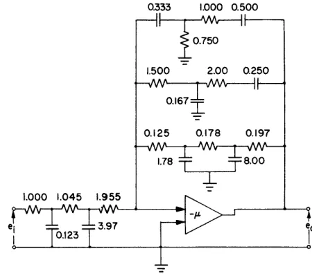
and the realizations are carried out to control the zeros of the transfer admittances. The resulting realization is shown in Fig. 8, where the impedance of the networks
0.333 1.000 0.500
~
1.500 2.00 0.250
0.167
I
0.125 0.178 0.197
1.78 T
'--....,l.--~
Fig. 8-Example of 1-amplifier realization. Element values in megohms and microfarads.
has been increased by a factor of 106, and the realized transfer function differs from the specified transfer function by a constant gain factor of
i.
The number of required passive elements is 18; the range in capacitor values is 48 to 1, and the range in resistor values is 16 to 1.The 3-amplifier synthesis can be carried out effectively by selecting
G(s)
=
(s+
l)(s+
8)(s+
16). (37) Substitution of this particular G{s) along with N(s) andD(s) from (27) into (21) and (22) gives, except for a constant multiplying factor,
and
1
YA-Yc =
-s
+
16(s
+ :)
(S2+
2s
+
16)YB-YD = .
(s
+
l)(s+
8)(38)
(39)
The right-hand sides of (38) and (39) now may be ex-panded in partial-fraction forms as
0.0625s
YA - Yc
=
0.0625 [image:11.612.326.551.201.402.2]and
1 1.61s 8.86s
y B - y D = S + - + - - - , (41)
2 s+l s+8
which may be realized as shown in Fig. 9. The
imped-1.00
2.00
0.250
Fig. 9-Example of 3-amplifier realization. Element values in megohms and microfarads.
ances of the A and C networks have been increased by 15.6 X 10³, and the impedances of the Band D net-works by 106
• The realized transfer function differs from the specified transfer function by a constant gain
o
-6 -12 g-18
fa
o
~-24
w
o
:::>
~ ~-30 :E
«
-36 -42
~
~ ~ ~
""
... ~
~
~
r\ AMPLITUDE
~
~~
;>--.-::_-I'-~ ~
-
'\~\,
PHASE\
1\
~
\ \
\'
\,
~
\~
\
- - THEORETICAL RESPONSE
,
~vr'
I - - - ... - I-AMPUFIER REALIZATION \
--<>---- 3-AMPLIFIER REALIZATION
"
~1\
I I I I I I -1-1
~,r-t-01 02 030.4 060.81 2 3 4 6 8 10 20 30 40
FREQUENCY IN RAD/SEC
Fig. IO-Response data.
30
o
30
C/l
W
w
-60$
w o
z
-90-w
!fl
I
1200..
150 -180
factor of 8. The number of required passive elements is 9. The range in capacitor values is 6.43 to 1, and the range in resistor values is 17.7 to 1. The range of ele-ment values for this example is so small that no practi-cal difficulty arises in building the networks; conse-quently, no necessity exists for reducing the spread by adjusting G(s).
To test the synthesis procedures experimentally, the realiza tions shown in Figs. 8 and 9 were constructed from paper capacitors and carbon resistors. Element sizes were adjusted to be within 1 per cent of the re-quired values. The measured amplitude and phase characteristics of the realizations together with the characteristics computed from (27) are shown in Fig.
10. Agreement between the measured curves and the desired characteristics demonstrates the soundness of the synthesis. At high frequencies the deviations in the phase curves fall within the limits of error of the experi-mental procedure employed.
CONCLUSIONS
The example shows that either of the two synthesis procedures illustrated in this paper is practical for realizing a 4-pole transfer function. The l-amplifier method utilizes a minimum of active equipment but requires the more complex synthesis calculations and a greater number of passive elements. If more complex transfer functions are to be realized, the passive net-works associated with the l~amplifier realization become impractical because of the number of elements and the spread of element values. Therefore, this method is most suitable for realizing transfer functions no more compli-cated than (27). The 3-amplifier realization requires more active equipment but simplifies the synthesis calculations and reduces the complexity of the passive networks. As the complexity of the transfer function increases, the advantages of the method rapidly become more apparent.
1955 WESTERN JOINT COMPUTER CONFERENCE 13
Simulation by Modeling
N. L. IRVINEt
ANDL. DAVIst
INTRODUCTION
S
IMULATION by modeling may be classified into three related methods.1. We may use analog models which obey the same laws as the phenomena we wish to study. Instru-ments such as network analyzers, slide rules, and elec-trolytic tanks are examples of devices that are used to make analog models.
2. We may use mathematical models to describe phenomena we wish to study. Quite often we resort to high-speed computing machines or differential analyzers to solve specific problems from the equations derived in our ma thema tical models.
3. We may subject scaled models of equipment to actual or simulated environments. Wind-tunnel testing of airfoils is a notable example. Actual equipment may also be subjected to simulated expected or known en-vironments, for example, experimentation with person-nel and equipment in high-altitude chambers.
Many of our complex phenomena may be studied effectively by simulation. The design of multidimension filters, sometimes called space filters, may be studied in this manner.l We are all familiar with the problem of detecting a message from an electrical signal which contains the message and noise. Suppose we wanted to detect a particular geometric shape in a field which contained a large number of configurations as well as the desired form. Let us choose the letter Z as our geometric shape, surrounded by a number of other con-figura tions; we could detect our letter Z by surveying the entire field with a filter which had the letter Z de-tailed to give full transmission while the response of the remainder of the filter gave small transmission. Obviously, when the configuration of the filter matches the desired information, a high degree of transmission is obtained, compared with that obtained from a non-matching condition. If we were to reverse the Z to OS we would not be able to find our message.2
A special case of this type of filtering is that in which a small aperture is used to scan the field. This technique may in general be treated as a unidimensional process, and it has been rather thoroughly explored for many scanning devices, such as equipment for the facsimile process and for television.
In general, space filtering may be extended to n
dimensions, where color, intensity, and location as well as geometric shape may be introduced. The analogy
t Aerojet General Corp., Azusa, Calif.
1 P. Elias and D. S. Grey, "Fourier treatment of optical
proc-esses," Jour. Opt. Soc. Amer., vol. 42, p. 127; February, 1952.
2 R. C. Jones, "Detection of Targets Against the Sky
Back-ground," Rep. 535, Polaroid Corp., Cambridge, Mass.; Apri112, 1954.
between the unidimensional electronic-filter problem and the multidimensional filter problem is quite com-plete. The methods of analysis of space filtering are an extension of the usual techniques for dealing with filters in electronic circuits. In both cases, the output from the filter is a linear weighted average of the input informa-tion; thus, the weighting function of a filter is deter-mined. In both cases, the problems are as follows:
1. To design a method for searching for a given type of signal.
2. To reproduce a signal, with discrimination In favor of a desired signal and against others.
3. To improve a signal, i.e., to remove distortion.
DISCUSSION
In electronic circuitry, the input and output messages are described in terms of frequency response and fre-quency content; thus, the independent parameter is time. With certain restrictions, any single-valued func-tion of time has a Fourier transform as a funcfunc-tion of frequency. Similarly, any general field distribution in space has a Fourier transform, but since the space tribution is a function of lengths, the transformed dis-tribution is a function of reciprocal lengths or wave numbers. Rapid changes of the function in space will give relatively large high-wave-number components in the spectrum, just as rapid changes of amplitudes of electrical signals give large high-frequency components. A unidimensional field distribution will have a uni-dimensional Fourier transform. In the case of a planar field distribution, the transformed function will be of two wave-number variables where the two-component position vector forms a two-component wave-number vector.
Let us look more closely at the similarity between the transforms used in electronic filter design and the
n-dimensional transforms. The transform of f(x) is as follows:
(1)
and under certain conditions 1
foo
f(x)
= -
F(k)e-ikxdk.271" -00
(2)
For the n-dimensional field, we define the field posi-tion vector
R,
and it can be shown that under suitable conditions the functionfeR)
has a Fourier transformwhere K·
R
is the usual dot product notation for vector operations, and for an n-dimensional Cartesian co-ordina te systemAnd (3) is
F(kr, k2 ... kn )
=
r:r:
A rigorous treatment may be found in several texts.3 (4)
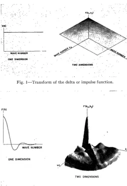
Let us confine our attentions to the two-dimensional case and look at some commonly used functions trans-formed in one dimension and then in two dimensions (shown in Figs. 1 and 2).
F{k) 1
I
Fig. I-Transform of the delta or impulse function.
ONE DIMENSION
TWO DIMENSIONS
Fig. 2-Transform of a square pulse.
Suppose we have a two-dimensional signal, J(x, y),
which contains the desired message, Sex, y), and an unwanted component N(x, y). From this signal we wish
to detect, discriminate, and reproduce this message as accurately as possible. Generally, we cannot optimize both the detection and discrimination characteristics at the same time, since an optimum detector leads to a filter design which maximizes signal-to-noise ratio and
3 I. N. Sneddon, "Fourier Transforms," McGraw-Hill Book Co.,
Inc., New York, N. Y.; 1951.
optimum discrimination implies the minimizing of the mean square error4 between the desired message and the
actual output message from the filter.
We may define the filter weighting function W(x, y)
in a manner similar to that in electrical theory. Then, within the restrictions mentioned before, the Fourier transformations are valid and we can define the auto-correlation function, c/>(x, y), and the power spectrum,
I(kx, ky):
",(x', y') =
r:r:
W(x, y)W(x+
x', y+
y')dxdy (6)and
(7)
As in electronic analysis, the Fourier treatment is limited to linear operations. A linear operation upon a field distribution function of an n-dimensional argu-ment may be defined as one which replaces the value of the function at a point by a linear weighted average taken over the neighborhood at that point.
If we want to examine a field for a particular type of distribution, we must, for practical reasons, introduce some sort of scanning technique. Scanning usually implies a time variation in one or more of the n-dimen-sions.
We might let x vary with time and scan a large area
bit by bit. An example of this type of scanning is the facsimile process. Scanning may also be done by rota-tion, as in the early television cameras. On the other hand, if we add detail to the filter where the transmission is a function of x and y, we may sample much larger fields and even the entire field of interest at once.
If we examine a field distribution, J(x, y), with a filter whose weighting fUll(~tion is W(x, y), and we wish to determine mathematically the output from the filter, we must perform the following integrations:
E(x', y') =
r:r:J(X,
y)W(x+
x', y+
y')dxdy, (8)where the integration limits may take on values de-pendent on the field boundaries. We immediately recog-nize this as a form of the convolution integral and we can transform (8) to wave-number space:
E' (k., k.) =
f_: f_:
E( x, y)ew· ... ·.·)dxdy=
J'(kx , ky)W'(kx , k y).If we allow x to vary with time
x
=
vt,then
vkx
=
w,(9)
(10)
(11)
4 N. Wiener, "The Extrapolation, Interpolation, and Smoothing
[image:14.621.37.290.243.613.2]Irvine and Davis: Simulation by Modeling 15
and (9) becomes
At this point we must pause and consider the nature of the distribution function
It will generally be the superposition of two separate contributions denoted for convenience by
where the S subscript refers to the desired spectrum and
N to the undesired background. Then the output spec-trum is also resolvable into separate terms
Optimization of the filter function W'(w/v, ,ky), then must involve some criterion, such as maximizing the ratio of
I
Es'l
I
EN'I '
at least over some particular region in (w/v, ky), and the exact form of W' will depend on the criterion used.
Let us now consider a particular system of con-siderable practical interest. Let us suppose that we wish to detect a round source of radiation surrounded by a general distribution of radiation such as a clouded sky. We now are concerned with the problem of enhancing the signal from the round source, J s, as compared with
general background distribution, J N. To do this, we
may scan the field with an a ppropria te optical sysfem making use of a filter whose weighting function is W.
An example of a weighting functionS to be used is shown in Fig. 3.
For many possible forms of J N, which are of great
interest, the computation of the transforms in closed form is extremely difficult. The W function which would be determined as optimum for a particular configuration of J sand J N would no longer be so for a J s translated
with respect to J N. The computation involved in at-tempting to optimize such a space filter with purely analytical tools would be enormous.
A convenient alternative to this head-on analytical attack is to use the analysis to determine the significant fea tures of the J sand J N distributions and then
re-place them by simplified models which can be c'on-veniently simulated by optical-electrical-mechanical means. With such a scheme, a change in some parameter such as position or intensity is a matter of a simple dis-placement or the additio!1, of an optical attenuator.
5 R. C. Jones, "On the Theory of Scanning Reticles
(Episco-testers)," Rep. 542, Polaroid Corp., Cambridge, Mass.; May 25,1954.
L-=-~I 100% TranaiaaiOll
Fig. 3-Typical n-wedge optical filter-rotational scan.
Such a simulation would require a system incorporating the following features:
1. Capable of forming a real planar image of the simplified function model.
2. Accessibility of this focal plane to an experimental space filter element with the desired scanning motion: 3. An appropriate type of integrating photometer to measure the transmitted light.
4. For a scanning motion, the information is con-verted into a function of time; thus adequate electronic processing equipment is required.
A schematic of such a simulator is shown in Fig. 4.
PARALLEL LIGHT SOURCE
Fig. 4-Schematic of a space filter simulator.
In the operation of this simulator, the parallel light illuminates the field photograph J(x, y). Lens 1 focuses the image of J(x, y) on the filter W(x, y), and Lens 2 serves as a collector which concentrates all the energy transmitted by the filter onto the integrating photome-ter. From the photometer, we have an electric signal which is analyzed principally for frequency content. The scanning operation may be performed in three ways:
1. Movement of the field photograph, J(x, y). 2. Movement of the filter, W(x, y),
3. A combination of ,both.
The scanning operation depends upon the partiGular problem at hand. The motions may, fot example, be linear or circular.
photo-Fig. 5-Typical oscilloscope presentation from simulator.
graphs of several background distributions and super-impose on them a more brilliant spot to simulate our function J s. Let us choose a rotational scanning opera-tion where we rotate the filter shown in Fig. 3.
The signal from this system is converted to an elec-trical signal by the photometer and we may observe the output on an oscilloscope (Fig. 5) and indeed be able to obtain a frequency spectrum by using a wave analyzer. We may, in this way, examine many sizes and intensities of spots and the effect of the different backgrounds on our output signal.
It is interesting to note a very special case where our spot is made very small and the background removed; this condition approaches the unidimensional case. A plot of the transform is shown in Fig. 6.
CONCLUSIONS
The analogy between the two-dimensional space filter problem and the one-dimensional electrical filter prob-lem is seen to be formally complete. The necessity to obtain time dependent space filtering, for various prac-tical applications, modifies the formal symmetry of the analogy without changing the basic two-dimensional
Fig. 6-Transform of n-wedged filter.
character. In many cases of electrical filter design. the analytic attack, though straightforward, proves to be less direct than an analog computation. Similarly, for the two-dimensional filter, an appropriate analog, to-gether with our analytic understanding of the filter process, provides the designer with an effective solution for his problem.
Ideal Transformers In the Synthesis of
Analog Computer Circuits
R. H. MAcNEALt AND
G. D.
McCANNt
INTRODUCTION
T
HE NEED FOR ideal transformers in the solu-tion of network synthesis problems, especially in multi-terminal problems, has long been recog-nized.I - 3 Nevertheless, there has been a general feeling that solutions to synthesis problems containing ideal transformers are of little more than academic interest because of the impracticability of constructing trans-formers good enough to be called ideal. 4 Wheneverpossible, inductances in the network are associated with the transformer so that it can be replaced by coils t Department of Electrical Engineering, California Institute of Technology, Pasadena, Calif.
1 W. Cauer, "Ideale transformatoren und lineare
transforma-tionen," Elec. Nach. Tech., vol. 9, p. 157; May, 1932.
2 W. Cauer, Ein Reacktanztheorem; Sitz. d Preuss Akad. der
Wissen; Phys. Math., pp. 673-681; 1931.
3 C. M. Gewertz, "Network Synthesis," The Williams and Wilkins
Co., Baltimore, Md.; 1933.
4 R. Bott and R.
J.
Duffin, "Impedance synthesis without use oftransformers," Jour. Appl. Phys., vol. 20, p. 816; August, 1949.
having self and mutual inductance.2 This attitude toward the ideal transformer is inappropriate in at least one branch of electrical engineering where network synthesis techniques are employed, namely in analog computing of the direct analogy (or network analyzer) type.5 Such computers customarily operate in the audio frequency range and contain high quality passive circuit elements which are adjustable in small steps. In the design of such computers the choice between "ideal" transformers and mutual inductance coils is an easy one to make. The availability of "supermalloy,"6 which has an initial permeability of 70,000 or more makes
Ii H. E. Criner, G. D. McCann, and C. E. Warren, "A new device
for the solution of transient vibration problems by the method of electrical-mechanical analogy," Jour. Appl. Mech., vol. 12, pp.
135-141; September, 1945
E. L. Harder and G. D. McCann, "A large scale general purpose electric analog computer," Trans. AlEE, Part I, vol. 67, pp. 664;
1948.
6 R. M. Bozorth, "Ferromagnetism," D. Van Nostrand Co., New
MacNeal and McCann: Ideal Transformers in the Synthesis of Analog Computer Circuits 17
possible the design of ideal transformers which have parasite effects no more serious in practice than those of an ordinary inductor. The ideal transformer has in its favor a much greater versatility than the mutual in-ductance (making possible mutual resistance and capaci-tance) and probably a cost advantage as well, when the adjustability requirement is considered.
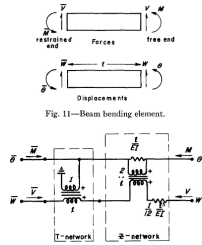
The use of ideal transformers in the design of analog computer circuits has been illustrated in a large number of papers, some of which are more than twenty years 0Id.7,s Most of these papers are concerned with the derivation of an electrical analogy for a specific type of physical system (e.g., bending of abeam, 9 pin-ended truss,7 airplane fuselage shelP 0). The approach of the present paper is somewhat more general than this, but still somewhat more specific than that of the network-synthesis theoretician. The field of interest is limited to analog computing, but the results are intended to ap-ply to the synthesis of analogies for all kinds of mechan-ical systems.
It is recognized that information concerning a com-plex system may be presented in a variety of different ways. The information may come as a detailed descrip-tion of the inner workings of the system, or this infor-ma tion infor-may alread y have been combined with the aid of general physical principles to form equations of state. Another possibility is that the information may come in the form of measurements taken in tests made on the system, or in tests made on parts of the system. In the la tter instance the parts maybe installed, or they may be removed from the system when tested. In some cases the information may be presented in all of these ways at once.
In the papers cited above which are concerned with the derivation of electrical analogies for specific systems, it is assumed that the information is presented as a de-tailed description of the inner workings of the system. The usual (or best) method employed for deriving analogies when information is presented in this fashion is first to subdivide the system to its ultimate elements-springs, masses, joints, beam bending elements, etc.; then to write down analogies for these elements by in-spection; and finally to interconnect the elements. When all or part of the information is presented in the form of equations of state or as the result of tests, this method is obviously impracticable for the parts of the system affected. Under such circumstances the system, or its affected parts, must be regarded as mechanical black boxes into which we are not permitted to look but which must be replaced with equivalent electrical black boxes which behave in an identical (or rigorously analogous)
7 V. Bush, "Structural analysis by electric circuit analogies," Jour. Franklin Inst., vol. 217, pp. 289-329; March, 1934.
8 R. R. M. Mallock, "An electrical calculating machine," Proc.
Roy. Soc., ser. A, vol. 140, pp. 457-483; 1933.
9 G. D. McCann and R. H. MacNeal, "Beam vibration analysis
with the electric analog computer, Jour. Appl. Meek. vol. 72, pp. 13-26; March, 1950.
10 R. H. MacNeal, "Electrical Analogies for Stiffened Shells with
Flexible Rings," NACA TN 3280; December, 1954.
manner at their terminals. Unfortunately from the point of view of the computer engineer, the number of such terminals is large and the methods for deriving the networks are not altogether straightforward.
The scope of this paper is restricted to the synthesis of systems characterized by ordinary algebraic equations with constant, real coefficients. For such systems gener-al methods of synthesis are well known.1
THE ALL-RESISTOR NETWORK
The need for ideal transformers in network synthesis problems can be illustrated by considering the limita-tions placed on the form of the equalimita-tions of a network not containing transformers, or, in view of the restric-tion to equarestric-tions with real coefficients, a network of resistors. We shall consider that the unknowns appear-ing in the equations of a network with
n+
1 nodes are the voltages from each of n nodes to a single reference node. The form of the equations written in matrix form is[v] [E]
=
[I]
(1a) orA network satisfying these equations for the case
n
=
3 is shown in Fig. 1. Values of conductance of theI,
1:>/-J 'J
Fig. 1-AU-resistor network.
resistors calculated by elementary network analysis are shown in the figure. The network in Fig. 1 is the most general all-resistor network with three independent node pairs. If all of the resistors in this network are to be
positive and bilateral, then the following restrictions must be placed on the coefficients in (1b).
n
L:
Vi j ~ 0i=1
i ~ j i, j
=
1 ... ni
=
1, 2 ~ .. n. (2)These conditions are far more restrictive than the general conditions for synthesis with passive elements
One way of easing the above restrictions is to trans-form the unknown variables by a linear co-ordinate transformation. Such a transformation might be a sim-ple scale factor multiplication (a diagonal transforma-tion) or it might involve the reduction of
[Y]
to the unit matrix, i.e., a solution of the problem giving[E]
ex-plicitly in terms of[f].
Such transformations are not generally permissible in theoretical network synthesis, nor are they permissible from the point of view of analog com pu ting. The terminal voltages[E]
and the input currents[I]
must be represented in the network. The practical reason for this is that the system repre-sented by (1) may well be only a part of a larger system, in which case[E]
and[f]
represent also the currents and voltages in other parts of the system.THE ALL-TRANSFORMER NETWORK
The equations of a three-winding ideal transformer, shown in Fig. 2, are
- = - = - ,
NI N2 N3 (3)
Ndl
+
N212+
N3I3 =o.
(4)Stated in words, the general conditions for an ideal, multiwinding, single-core transformer are that the volt-ages across the various windings are directly propor-tional to their turns ratios and that the sum of the ampere turns (magneto motive force) is zero.
Fig. 2-Ideal transformer.
Consider now the network of transformer windings shown in Fig. 3. All the coils in one horizontal row are wound on the same core of an ideal transformer. Coils in different rows are not magnetically coupled. The relative number of turns in each winding is indicated by the symbol Ti j • From the manner of connection and (3), the voltage EI is given by
EI
=
T 11EI+
T 12E2+
T 13E3 (5) or, in general,[E] = [T]
[Il].
(6)Also, from (4)
II
=
TnIl+
T'!.dz+
Talla (7)or, in general,
(8) (In this equation, the superscript t indicates that the matrix
[T]
has been transposed.)12
~l'---i
lie--i
E.l,---i
"F:;;- --1+
IJFig. 3-All-transformer network.
Eqs. (6) and (8) can be regarded as a workless trans-formation from variables
[1],
[E]
to variables[f],
[E],
since
[I]T[E]
=
[I]T[T][E]
=
{[T]T[I]}T[E]
=
[I]T
[E].
(9)
Hildebrand gives an explanation of the matrix identity employed in (9).11 Note that from the point of view of physical realizability the only restriction on the ele~ ments of
[T]
is that they be real numbers. Hence the network of Fig. 3 is capable of solving (6) with arbitrary real coefficients (if[T]
is nonsingular). Voltages[E]
are established by external generators and the voltages[E]
read off. A practical version of this network computer was invented by Mallock8 in 1933 and sold commer-cially. Considering the improvement in transformer iron in the last twenty years this network has inviting char-acteristics as a computer even today.
From the point of view of network synthesis a more important characteristic of this network is that it pro-vides an electrical means for carrying out a co-ordinate transformation. Thus the objection to co-ordinate trans-formation mentioned in the previous section is over-come because both the original and the transformed co-ordinates appear in the network. Let us apply the trans-forma~ion given by (6) and (8) to (1a):
[Y][T][E]
=
[I]
[T]T[Y] [T] [E]
=[1].
(10)11 F. B. Hildebrand, "Methods of Applied Mathematics,"
MacNeal and McCann: Ideal Transformers in the Synthesis of Analog Computer Circuits 19
Define
[Y']
=[T]T [Y][T].
Eq. (10) can be synthe-sized by inspection if a transformation can be found which reduces[Y']
to a diagonal matrix with either zero or positive elements on the principal diagonal and zero elsewhere. If such a transformation exists, the original admittance matrix [Y] is said to be positive semi-definite. Hence a sufficient condition for the passive synthesis of (1a) is that the matrix[Y]
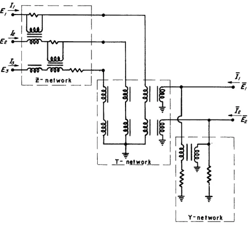
be positive semi-definite. An efficient transformer network for carrying out the synthesis is described in the next section.The co-ordinate changing properties of transformer networks have been used extensively in connection with the direct analogy type of analog computer.12 ,13 For example, they provide the means for interconnecting analogies for parts of a mechanical system which are oriented in different space directions (e.g., the intercon-nection of an airplane's fuselage and its swept-back wings). Fig. 4 shows a very simple transformer circuit for synthesizing a negative coupling element.
for '12>0
Fig. 4-Synthesis of negative coupling element.
CAUER NETWORKS
Cauer's network, as originally presented,1 synthesizes a system with equations presented in the form
The resulting equation in terms of transformed variables is
[E]
=
[R] [1],
where it is assumed that
and Rii~O.
Rll 0 0 ... 0
o
R22 0 ···0[R]
=
0o
R 33 · .. 0o
o
o ...
Rnn(13)
(14)
(If any Ru equal zero it is assumed that they occupy the last positions in the matrix. This condition can be sa tis-fied by rearranging rows and columns in the T matrix.)
Premultiply (13) by
[T]:
[E]
=
[T][E]=
[T][R][1J
=
[T][R][T]T[I]. (15)Hence
[Z]
=
[T][R][T]T. (16)The problem is to find matrices [T] and
[R]
which satisfy this equation. Let [T] be a triangular matrix of the form1 0 0 · .. 0
T21 1 0 · ··0
[T] Tn T32 1 · .. 0 (17)
Tnl Tn2 T n3 · .. 1
[Z][I]
=[E].
(11) ThenRn Rl1T21 RuT3l
RllT2l R22
+
RuT212 RllT21T3l+
R22T32 [T] [R] [T]T=
RuTsl RllT21T3l
+
R22T32 R33+
RuT3l2+
R22T322 (18). .
.. . . .
. .
.
. . .
...
In this section Cauer's network will first be derived in its original form and then in a form suitable for the synthesis of (la). It is assumed that the matrices
[Z]
and
[Y]
are positive semi-definite. This does not imply that they are necessarily nonsingular.As stated in the previous section, the network can be synthesized if a co-ordinate transformation is found which transforms
[Z]
into a diagonal matrix.Let this transformation be given by
[E]
=
[T] [E]
[1] =
[T]T
[I].
(12) 12 W. T. Russell, "Lumped Parameter Analogies for ContinuousMechanical Systems," Calif. Inst. Tech., Ph.D. thesis; 1950.
13 R. H. MacNeal, G. D. McCann, and C. H. Wilts, "The solution
of aeroelastic problems by means of electrical analogies," Jour. Aero. Sci., vol. 18, pp. 777-789; December, 1951.
Note that, given the elements of
[Z],
the elements of[T] and of
[R]
can be evaluated one at a time. Explicitly,Rn = Zn; T2l = Z12/Rn ; T3l
=
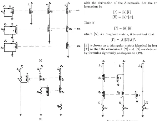
Z13/R n (19)The triangular transformation matrix is efficient from the point of view of electrical synthesis since fewer windings are required than in the case of a full trans-formation matrix. Cauer's "Z-network" is shown in Fig. Sea). The barred co-ordinates can be eliminated by placing the R's on the other side of the windings, as shown in Fig. 5(b). The total number of windings re-quired in the synthesis of n simultaneous equations by Cauer's network is n· (n+l)/2-1. If multiwinding transformers are not available, they may be replaced by
T.i2 - etc.
(a)
(b)
Fig. 5-Cauer's Z-network, (a) with barred co-ordinates represented, (b) with barred co-ordinates eliminated.
The necessary and sufficient conditions for the syn-thesis of (11) by Cauer's network may be stated in a way that does not involve matrix theory. If (11) is to represent a passive electrical network then it is evi-dently necessary that the input impedance at any given terminal must be positive (or at least zero) whether some, none, or all of the other terminals are short-cir-cuited. It is easy to demonstrate that this condition is also a sufficient one for the synthesis of Cauer's network. Every element in Cauer's network can be computed by the formulas in (19) so that the only real question is whether or not the resistors are positive. From inspec-tion of Fig. S(b) it is evident that Rll is the input im-pedance at terminal 1 with all other terminals open-circuited; R22 is the input impedance at terminal 2 with
terminal 1 short-circuited and all other terminals open-circuited; R33 is the input impedance at terminal 3 with
terminals 1 and 2 short-circuited, and all others open-circuited; etc. Hence all resistors are positive (or zero).
We will next construct Cauer's "Y-network" for a system specified by equations of the form of (1a). This network, shown in Fig. 6, is the "dual" of the
"Z-net-work" shown in Fig. S. The analysis proceeds by analogy
with the derivation of the Z-network. Let the trans-formation be
Then if
[1]
=
[S]
[1]
[E]
=
[S]T[E].
[1]
=[G][E]
where [G] is a diagonal matrix, it is evident that
[Y]
=
[S] [G] [S]T.
(20)
(21)
(22)
[S]
is chosen as a triangular matrix identical in form to[T]
so that the elements of[S]
and [G] are determined by formulas rigorously analogous to (19).E, Ee Es
I, ~ Ie
~
13i
\-
-I
+
.
S:JI
1-
SS21
~r;
G" G22 G33
Fig. 6-Cauer's Y-network.
Cauer's networks are important because of their gen-erality. Unfortunately for practical applications, the number of transformer coils required increases approxi-mately as the square of the number of terminals. On the other hand, under special conditions no transformer at all may be required (the all-resistor network). An im-portant unsolved problem is the determination of the
minimum number of transformers required to synthe-size a given system of equations and the construction of a network exhibiting this minimum number.14
SYNTHESIS OF SYSTEMS WITH "RESTRAINED" TERMINALS
Many of the problems that arise in analog computing can be translated -into problems in abstract network synthesis, but sometimes the problem is one that would not independently occur to a network theoretician as an interesting and useful problem on which to work. Such is the nature of the problem considered in this section. As has frequently been demonstrated, the abstract mathematical sciences depend for their growth on an influx of practical problems, however much these
prob-14