This is a repository copy of
Effect of lateral displacement of a high-altitude platform on
cellular interference and handover
.
White Rose Research Online URL for this paper:
http://eprints.whiterose.ac.uk/1829/
Article:
Thornton, J and Grace, D orcid.org/0000-0003-4493-7498 (2005) Effect of lateral
displacement of a high-altitude platform on cellular interference and handover. IEEE
Transactions on Wireless Communications. pp. 1483-1490. ISSN 1536-1276
https://doi.org/10.1109/TWC.2005.850282
[email protected] https://eprints.whiterose.ac.uk/ Reuse
Items deposited in White Rose Research Online are protected by copyright, with all rights reserved unless indicated otherwise. They may be downloaded and/or printed for private study, or other acts as permitted by national copyright laws. The publisher or other rights holders may allow further reproduction and re-use of the full text version. This is indicated by the licence information on the White Rose Research Online record for the item.
Takedown
If you consider content in White Rose Research Online to be in breach of UK law, please notify us by
Effect of Lateral Displacement of a High-Altitude
Platform on Cellular Interference and Handover
John Thornton and David Grace,
Member, IEEE
Abstract—A method for predicting movements in cellular cov-erage caused by lateral drift of a high-altitude platform (a quasi-stationary platform in the stratosphere) is developed. Cells are produced by spot beams generated by horn-type antennas on the platform. It is shown how the carrier-to-interference ratio (CIR) across these cells varies when the antenna payload is steered to accommodate the lateral movement of the platform. The geometry of the antenna beam footprint on the ground is first developed and then applied to a system of many cochannel beams. Pointing strategies are examined, where the pointing angle is calculated to keep, for example, a center cell or an edge cell in the same nominal position before and after the platform drift, and the CIR distribution is calculated. It is shown that the optimum pointing angle depends on the desired level of CIR across the service area, typically lying between3±0
.75
◦
for a platform drift of 2 km and corresponding to a cell in the middle ring. It is shown that it is necessary for a significant proportion of users to perform a handover to maintain a given CIR after platform drift. The analysis reveals that there is an optimum pointing angle that minimizes the probability of handover for a particular value of drift and CIR.
Index Terms—Antennas, broadband communication, high-altitude platforms, interference.
I. INTRODUCTION
W
ITH an ever increasing demand for capacity for futuregeneration multimedia applications, service providers are looking toward the millimetric wave bands. One possible means of their exploitation is the use of high-altitude platforms (HAPs) [1]–[14], which will operate in the stratosphere at an altitude of 17–22 km. HAPs have the potential to provide line-of-sight links to a large number of users situated over a large geographical area and use considerably less communications infrastructure than that required if delivered by a terrestrial network. Such systems will employ a cellular architecture in order to provide overall system capacity, with cells served by a number of antenna spot beams from the HAP.
The performance of terrestrial cellular architectures has been described by Lee [15]. To provide wide coverage, the cells are tessellated, with different channels assigned to neighboring cells in order to manage cochannel interference; assignments can take the form of frequencies, time slots, or codes. Conven-tionally, cells are clustered into groups of three, four, seven, or
Manuscript received July 26, 2002; revised June 5, 2003; accepted April 26, 2004. The editor coordinating the review of this paper and approving it for publication is A. Molisch. This work was supported by the HeliNet (IST-1999-11214) and CAPANINA (FP6-IST-2003-506745) projects, part of the FP5 and FP6 European Union funding initiatives, respectively.
The authors are with the Department of Electronics, University of York, Heslington, York YO10 5DD, U.K. (e-mail: [email protected]).
Digital Object Identifier 10.1109/TWC.2005.850282
nine, dividing the overall frequency allocation between them. The larger the number of cells in the cluster, the greater the reuse distance and the higher the carrier-to-interference ratio (CIR), but the fewer the number of channels per cell; this trade-off is fundamental to most cellular systems. Fixed channel assignment has been shown to produce the highest capacities in nonshadowed environments, but when the traffic load per cell varies, dynamic channel assignment has been shown to provide higher capacity [16]. Dynamic channel assignment is also particularly useful when the environment and/or the traffic load are hard to predict [17]–[21].
A major difference between HAP and terrestrial cellular architectures is the station-keeping characteristics and stability of the platform, and this has been highlighted by a number of aeronautical programs based on airship- and aircraft-type platforms [1]. An emerging body of work [2]–[13] has been ex-amining other communications challenges in increasing detail. However, the effects of HAP station-keeping on cellular com-munications system performance have yet to be examined in depth. This is partially because it has been difficult to determine accurate specifications for platform movement owing to the scarcity of data regarding their actual aeronautical performance. The International Telecommunications Union has specified that such platforms should be kept within a circle radius sphere
of 400 m with height variations of ±700 m [9]; the HeliNet
project has specified two position cylinders that depend on platform availability [7], and the HALO project has suggested that its platform will remain within a toroid of 4–6 km [10]. This work, however, sidesteps this issue and sets out to develop generic models for the effects of platform instability on cellular interference characteristics, with an aim to identifying strate-gies for accommodating a range of platform movement. Our emphasis is on broadband fixed wireless access-type services typically operating at 28 GHz and above. For this application, the required antenna efficiency and sidelobe suppression are most likely to be offered by aperture- or horn-type antennas. These imply nonadaptive beams that may require mechanical ground stabilization and/or steering. These effects will be ex-plored in this paper. In Section II, the geometry of the HAP and cell footprint is introduced and the effect of platform roll angle is investigated. This analysis will be used in subsequent sections to determine CIR performance when the antennas are subject to different pointing angles in order to correct for plat-form displacement. Section III then quantifies the system level performance in terms of CIR values resulting from different antenna pointing strategies that are employed to compensate for platform displacement. Three strategies are examined: center cell correction, edge cell correction, and optimized correction.
1484 IEEE TRANSACTIONS ON WIRELESS COMMUNICATIONS, VOL. 4, NO. 4, JULY 2005
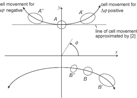
Fig. 1. Displacements of cell footprints in the plane of the groundxyfor
platform roll angle change.
Section IV then quantifies the performance from the user’s perspective, evaluating the probability that handover is required and the probability that handover is desirable as a way of maintaining quality of service to the user.
II. GEOMETRY OF ACELLFOOTPRINTSUBJECT
TOPLATFORMROLL
Here we show how the footprint of a cell is changed when the HAP experiences a change of roll angle. A similar problem is addressed by [2] in the context of a code division multiple access cellular network. In [2], an approximation is made where a cell is assumed to follow a straight line when there is a change
in platform roll angle.1We introduce a more general description
of the cell’s displacement that is illustrated in Fig. 1. Here
the trajectory of the cell describes a curve that yields bothx
andydisplacements, this being particularly important for more
distant cells and large values of platform roll angle.
In Fig. 1, for a platform roll angle relative to thex–y plane
(∆ϕin Fig. 2), a cell on thex-axis would undergo displacement
along thex-axis only. However, for a cell on they-axis such as
footprintA, a platform roll angle change yields displacement
in bothx andy on the ground. Here, the cell footprintA is
assumed circular, having been formed from an antenna beam that is asymmetric, i.e., it has different beamwidths, in the elevation and azimuth planes, which are chosen to yield a
circular cell.2 Cell footprints A′ and A′′ are distorted and
result, respectively, from positive and negative roll angles of
the platform. FootprintsB,B′, andB′′show an equivalent but
more general case for a cell footprint that lies on neitherx- nor
y-axis.
The new antenna pointing angles may be derived by con-sidering the circle through which the antenna boresight passes following a change in platform roll angle, as shown in Fig. 2,
where the platform is on station at pointsat heighth. Pointa
is the cell center, on thex–y plane of the ground, before the
1El-Jabu and Steele [2] use the term “inclination” where we use “roll.” The
terms are interchangeable here.
2Such an antenna has been reported whereby an asymmetric lens is used to
shape the beam [22].
platform experiences a change in roll angle. When the platform
roll angle changes by∆ϕ, the boresight passes through point
pon a circle that is centered at x= 0,z=zp,y=ya and is
parallel to thex–zplane. The new boresightsa′ intersects the
x–yplane at the new cell centera′. By deriving the coordinates
of pointp, the new boresight pointing angles can be derived.
The “roll circle” has radiusrcgiven by
rc=
h
cosϕ (1)
whereϕis the angle of the original cell centerawith respect to
the axis of platform roll
ϕ= arctanxa
h (2)
and, after [2], the original point where the beam intersects the
ground a (which we also define as cell center) has xand y
coordinates given by
xa =htanθ0cosφ0 (3)
and
ya=htanθ0sinφ0. (4)
The antenna boresight elevation and azimuth pointing angles
are, respectively,θ0, measured with respect to the platform local
vertical, andφ0, measured on thex–yplane with respect to the
x-axis. The Cartesian coordinates of pointpare
xp=rcsin(ϕ+ ∆ϕ) (5)
and
yp =ya (6)
and
zp=h
1−cos(ϕ+ ∆ϕ)
cosϕ
. (7)
The new boresight azimuth and elevation angles, respec-tively, are
φ′= arctan yp
xp
(8)
and
θ′= arctan
x2
p+y
2
p
h−zp
. (9)
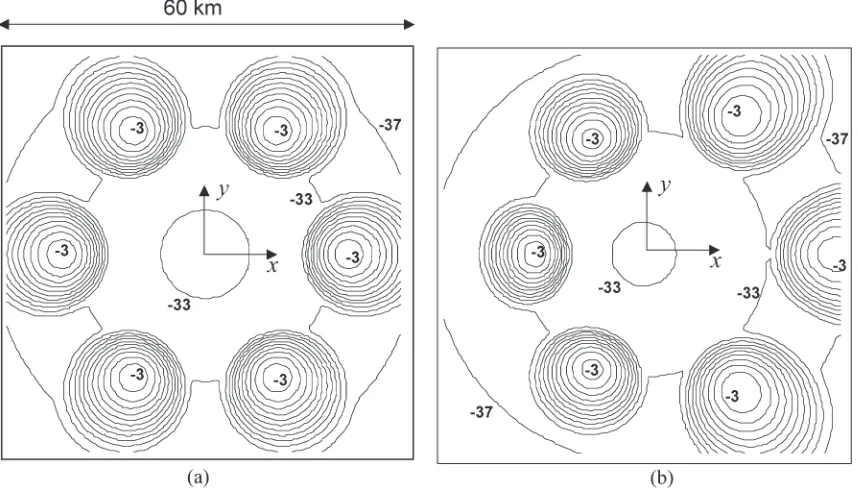
Fig. 3 illustrates the effect of roll angle change on the power contours for a nominal group of six cells, where in case (a) the
boresight pointing elevation angle for each cell is 52◦, the HAP
is at a height of 17 km, and the cells are spaced in azimuth at
integer multiples of 30◦. The power contours of the cells are
[image:3.594.312.554.410.514.2]initially circular, being formed from asymmetric beams. The power contours are at 3-dB intervals and the directivity of each antenna is 26 dBi.
Fig. 2. Change in antenna pointing angles following platform roll∆ϕ.
Fig. 3. Effect of platform roll angle on six nominally circular cells’ power footprints (power contours are relative to cell center power and spaced by 3 dB). (a) Zero platform roll. (b)+8◦platform roll.
cell centers first introduced in Fig. 1. The method may now be extended to derive changes in CIR for a cochannel cell group. In particular, we may study the consequence of mechanically steering a group of antennas toward the nominal center of the service area when the platform is laterally displaced from its intended position as discussed in Section I above.
III. RESULTS FORANTENNAPOINTING ON A
NETWORK OF121 CELLS
[image:4.594.81.510.401.648.2]1486 IEEE TRANSACTIONS ON WIRELESS COMMUNICATIONS, VOL. 4, NO. 4, JULY 2005
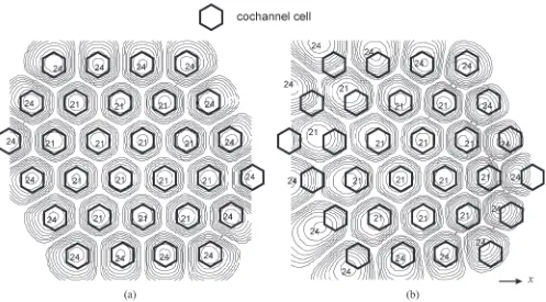
Fig. 4. CIR contours for channel one of four (the spacing is 3 dB and the CIR of the highest value contours is labeled in decibel). (a) Zero displacement. (b) 2-km displacement, central cells corrected.
compensate for lateral drift in the platform. Thus, (8) and (9) may be used to derive the antenna pointing angles for each cell and the method of [8] to derive CIR values. To briefly review [8], CIR is calculated in each cell as the ratio of the power received from the main antenna beam and the sum of the powers from all the other cochannel beams.
The CIR level is important because it determines the modu-lation and coding schemes that can be used: the higher the CIR the higher the data rate that can be accommodated. For example, coded quaternary phase-shift keying (QPSK) requires a signal-to-noise ratio (SNR, assumed here to be equivalent to CIR) of at least 2.9 dB and will carry 1.38 b per symbol, whereas uncoded 64 quadratic-amplitude modulation requires an SNR of at least
25.5 dB and will carry 6 b per symbol3[7]. When the platform
suffers lateral displacement, the cell footprints on the ground will undergo an equal lateral movement, unless compensated for by angular adjustment in the antenna payload. This dis-placement of the cellular pattern may lead to loss of service for users near the edge of the intended service region while for other users the cell movement may lead to a requirement for handover to another channel. These effects may be decreased if the platform antennas can be pointed towards the original cell center locations. We choose to steer the antenna group as one in order to reduce mechanical complexity. The geometry for the new pointing angles, power and CIR contours, is equivalent to that described in Section II for changes in platform roll angle.
A standard four-channel reuse scheme is used here, where the total service area has a diameter of 60 km and the HAP is at
3For codedQPSK code rate = 0
.6912(rate 3/4 convolutional inner code
and 188/204 Reed–Solomon outer code). Both assume a filter roll-off factor of 25% and a bit error rate of10−5.
a heighth= 17 km. The antenna main lobes are modeled after
[8] and the sidelobes are assumed to be a flat floor at−40 dB
below peak directivity for each antenna. (These simple models have been used so that the effects of beamwidths, cochannel cell spacing, and platform displacement can be studied with greater clarity because the system has many variable parameters [8], [14].) Fig. 4(a) shows the CIR contours for one of four channels, for zero platform displacement, and therefore without an applied antenna pointing correction.
Three pointing strategies are assessed in the next subsec-tions: center cell correction, edge cell correction, and optimized coverage correction. Results are obtained using the equations
above by calculating the CIR at each point(x, y). The spacing
of these points depends on the spatial resolution required, and we have found that an interval of 0.625 km is adequate. Contour plots are then used to determine the fraction of the coverage area affected with each strategy. In some cases, so as to illustrate areas of coverage, an arbitrary CIR level has been used—areas with CIR above this level are colored in grey, areas below are shown in white.
A. Center Cell Correction
Here, a pointing angle is derived that always ensures that the center cell is positioned in the center of the service area. This requires a change in antenna pointing angle
∆ϕ= arctand
h (10)
where d is the platform drift. The effect of applying this
Fig. 5. Effect of platform drift on the fractional coverage of the fixed cell group where central cell position is used to choose antenna pointing angle.
Fig. 4 illustrates the distortion of the geographical coverage—the CIR contours are at 3-dB intervals and the labels are for the highest contour values. To aid comparison, the boundaries of the hexagonal cells are also shown. In case (a), it is apparent that the peak CIR values are geographically aligned with the cells. In case (b), while the central cells are little affected, for many of the outer cells the regions of peak CIR have moved out of the cell. The effect of this CIR degradation is quantified in Fig. 5, which plots the fractional area of the cells on this channel served at or above a given CIR value for different platform displacements.
While Figs. 4 and 5 appear to show a fairly severe degrada-tion of CIR coverage, the reality is that the coverage provided by the channel is moving into regions other than the original cell group. That is, the notion of geographically fixed cells is leading to a situation where the coverage for the cell group is reduced—while zero displacement yields 100% cell coverage at 15.5 dB CIR, this reduces to 75% following the application of the pointing angle used to correct the central cells following a 2-km platform drift.
However, to make a more complete study, we may consider the coverage when handover to another channel is allowed. This implies disregarding the notionally fixed cells (i.e., where a user is tied to a single channel) and considering the coverage on any channel for the entire service area. This requires computation of CIR as a function of ground position for all
four channels and can be calculated by applying Boolean OR
at each ground point to test if any channel is above a given CIR level. The coverage in this case is shown in Fig. 6 for several HAP displacements and pointing angle corrections. The use of a handover strategy requires that the ground terminals can receive any channel [13] (discussion of specific strategies is beyond the scope of this paper).
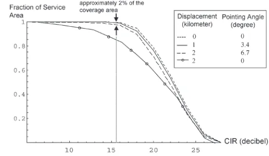
In Fig. 6, we see that where the coverage area as a whole is considered and handover between channels is allowed, the CIR degradation is actually quite small. For example, the arrowed region in Fig. 6 shows the difference in coverage before and after platform displacement of 2 km with the
associated 6.7◦antenna pointing correction, where the coverage
[image:6.594.39.295.70.219.2]at the original 15.5-dB level has dropped to approximately 98%. The remaining 2% of the service area receives CIR coverage at between 7 and 15.5 dB. This region is at the very
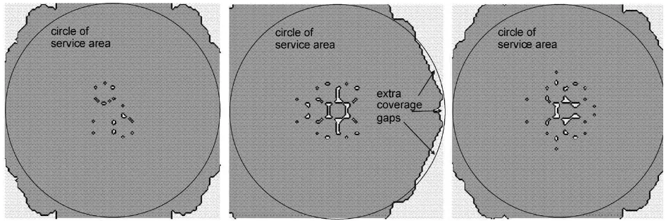
Fig. 6. Effect of platform drift: fractional coverage on any of the four channels for the entire service area for different choices of antenna pointing correction.
edge of the service area; arrowed in Fig. 7(b) that shows the additional area that has dropped below the level compared to Fig. 7(a). In Fig. 7, an arbitrary CIR level of 16 dB has been used to illustrate where such small gaps in coverage occur at this level—areas above 16 dB are shown in grey, areas below 16 dB appear as white gaps.
The gaps are a consequence of the spatial overlap of the antenna radiation patterns. The CIR level has been chosen here so that nearly all the service area experiences this level. Hence, it is useful to show that where the white area increases [Fig. 7(b)], the system performance is being degraded. Our rationale is to choose the antenna pointing strategy that minimizes the degradation of the quality of service. In the following sections, it will be shown that the residual CIR and coverage degradation of Fig. 7(b) can be eliminated by careful choice of antenna pointing angle.
B. Edge Cell Correction
It is apparent in Fig. 7 that there is a tendency for CIR coverage to extend beyond the nominal 60-km diameter service area. When the angle from (10) is applied as a pointing angle to correct for platform displacement, the coverage tends to be
extended toward −xwhile being truncated toward +x. This
would suggest that the angle from (10) overcompensates for displacement for most cells across the coverage area as a whole and should be reduced. This can be achieved by instead cor-recting the position of a cell on the edge of the service area—an “edge cell.” This is equivalent to the difference in the subtended elevation before and after platform displacement, i.e.,
∆ϕ= arctanrc
h −arctan rc−d
h (11)
wherercis the radius of the service area (30 km in this
1488 IEEE TRANSACTIONS ON WIRELESS COMMUNICATIONS, VOL. 4, NO. 4, JULY 2005
[image:7.594.306.552.268.449.2]Fig. 7. Coverage gaps for four channel schemes where handover to any channel is allowed at 16-dB CIR level (dark shading is above this). (a) Zero displacement. (b) 2-km drift, center cells corrected. (c) 2-km drift, revised correction.
Fig. 8. Effect of platform drift: comparison of coverage for the fixed cell group (one channel only, handover not allowed) for different pointing corrections.
CIR degradation in terms of the geographical area of a fixed cell group served on a single channel (handover not allowed). The implication here is that because the average CIR reduction is less severe, fewer users will need to handover to another channel in an attempt to re-establish the CIR they experienced before the platform was displaced. Thus, the above study has shown that a relationship exists between platform displacement, the associated choice of antenna pointing correction, cellular CIR coverage, and the likelihood of handover being required.
C. Optimized Coverage Correction
An optimum pointing angle for a specific channel and desired CIR level can be derived. This may be found numerically by examining the fractional coverage available at a specific minimum CIR for different pointing angles as shown in Fig. 8 and the fractional coverage as a function of pointing angle for various fixed CIR thresholds as shown in Fig. 9.
Fig. 9 affords considerable insight into many aspects of the system, which we will briefly discuss. For each CIR threshold shown, the intercept at the coverage axis shows the fractional area of a fixed cell group that is served at or above the threshold when zero pointing angle is applied to the antenna
Fig. 9. Coverage versus antenna pointing angle, for various CIR thresholds, for channel one of four (without handover) and 2-km lateral platform drift.
payload. Relative to this, the maximum of each curve shows an increase in coverage. Interestingly, this optimum angle is not constant for each curve but falls within a fairly narrow range
(3±0.75◦)—the deviation occurs because the centers of the
CIR contours, as illustrated in Fig. 4, are not exactly colocated due to the path length difference across the cell. This angular range corresponds to cells lying in the middle rings of the
service area. When this 3◦angle is applied, coverage on any of
the four channels (i.e., when handover is used) approaches the curve for zero platform displacement shown in Fig. 8 almost exactly—hence, CIR at any point will be maintained at between 15.5 and 27.5 dB. To guarantee that CIR does not fall below the 15.5-dB minimum, 9% of the cell group area requires handover to another channel, which is apparent from the arrowed region in Fig. 9.
IV. PROBABILITY OFREQUIREDHANDOVER
ANDSUCCESSFULHANDOVER
[image:7.594.44.291.270.439.2]present a method of predicting the probability that handover to another channel is required in order to maintain at least the same CIR following a platform lateral drift, and also quantify the associated influence of antenna pointing correction. These measures quantify the spatial effects due to the platform drift and changes to the cellular coverage rather than quantifying the temporal effects such as the frequency of handover arising from the platform movement dynamics. Temporal effects are beyond the scope of this paper and will be highly dependent on platform type. Recalling that from [8] the CIR at each ground position (or “element”) can be derived, we may use set theory notation to aid a comparison of CIR coverage before and after
the platform drift and antenna pointing correction.T is the set
of all elements within the coverage area, so the set of elements
(E)withinT that is above or equal to a CIR threshold xon
a single channel when the HAP is located at pointp(over the
subplatform point) is
E ={e∈T :e(n, p)≥x} (12)
wherenis the index to the single channel of interest andpis
the index referring to the CIR values obtained when the HAP
is at pointp. Similarly, after the platform has moved to a new
locationp′, then
E′={e∈T :e(n, p′)≥x} (13)
where eis now in the set of elements within set T that have
their CIR above (or equal to) the thresholdxon the single
chan-nel. Several performance measures can be defined using the
above. The probability that the CIR remains abovexafter drift
(Pa, x)is
Pa, x=
|E∩E′|
|E| (14)
and the probability that the CIR decreases belowxafter drift
(Pb, x)is
Pb, x= 1−
|E∩E′|
|E| or Pb, x=
|E\E′|
|E| . (15)
This is also the probability that handover is desired. We now
define the setH′as the elements in the original setT that are
above the thresholdCIRx on an alternative channel after the
HAP has drifted top′:
H′={e∈T :e(n, p′)≥x, n∈C\CI} (16)
where n is the channel index, C is the set of all channels
in the system, and CI is the set containing only the original
channel of interest. That is,H′contains all the elements where a
handover can be supported successfully. Hence, the probability that handover is successful(Ph, x)is
Ph, x =
|E∩H′|
[image:8.594.306.550.70.228.2]|E| (17)
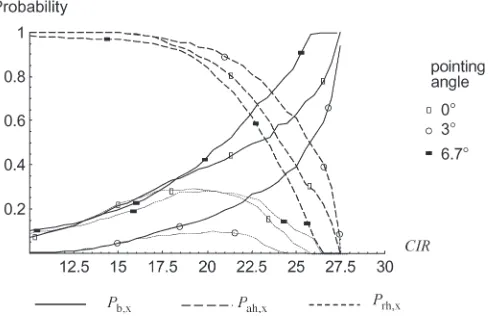
Fig. 10. Probability of required handover, required and successful handover, and continuity of CIR following the 2-km platform drift.
and probability that handover is required and successful
(Prh, x)is
Prh, x=
(E\E′)∩H′
|E|
. (18)
The probability that a user will continue to remain above
the thresholdxafter drift, assuming handover to an alternative
channel is allowed(Pah, x), is
Pah, x=
|E∩(E′∪H′)|
|E| . (19)
Fig. 10 shows (15), (18), and (19) evaluated as a function
of xfor three cases of pointing angle. Fig. 10 presents some
interesting results that should be interpreted in the context of the coverage plots shown in Fig. 6, which show that fewer users experience the higher CIR. Fig. 10 illustrates that these users are more likely to require handover to another channel to maintain their CIR and that handover is less likely to be successful, indicating that the links at higher CIR are less stable. The effect of pointing angle is also apparent in Fig. 10. Interestingly, an excessive angle increases the need for handover, exceeding that for zero pointing angle, although the total coverage after handover (Fig. 6) is rather worse for the zero angle case. When the optimum pointing angle is chosen
(i.e., 3◦), the probability of handover being required(P
b, x)at
a given thresholdxis minimized while the probability of CIR
continuity(Pah, x)is maximized. Also, while coverage at a CIR
level can be maintained on average across the coverage area, handover is still required on a location-by-location basis as the peaks in CIR move around. In summary, the effects of lateral displacement can largely be mitigated using the developed antenna pointing strategy and handover. Nodes experiencing a high initial CIR are more likely to be affected than those with low initial CIR. However, effective use of adaptive modulation and coding will ensure that users will in general be able to maintain a minimum data rate.
V. CONCLUSION
1490 IEEE TRANSACTIONS ON WIRELESS COMMUNICATIONS, VOL. 4, NO. 4, JULY 2005
steered, aperture-type antennas that serve a cellular network from an HAP has been presented. These have been expressed in terms of the CIR on the ground that is derived from the overlap of the power footprint of each antenna, whose radiation patterns are modeled using curve-fit approximations. A derivation of the footprints’ distortion as a function of platform roll angle has also been presented. These methods have been combined to model variations in CIR that would occur when the antennas are pointed, as a group, toward the center of the service area so as to accommodate lateral displacements of the platform (individual beam steering has not been considered).
An architecture of 121 cells using four channels has been in-vestigated in detail for lateral platform displacements up to 2 km. When handover is not used, it has been shown that the geographical coverage of a cochannel cell group suffers a deg-radation whereby the average CIR is reduced across all cells. Different strategies for deriving a correction angle for antenna pointing have been considered, and it has been shown that the correction required is somewhat less than the change in elevation angle associated with the central cell. When handover is used, CIR levels are not on average degraded, although handover is required on a location-by-location basis because the peaks in CIR move around. When a pointing angle that maxi-mizes coverage on a single channel is chosen, the probability of handover being required at a given CIR threshold is min-imized. Thus, the combined effects of the pointing strategy and handover mean that the negative effects of HAP lateral displacement can be largely mitigated.
The full extent of the positional instability of future HAPs is not yet well defined, and the work is intended to present the development of a prediction tool that can be used to characterize the performance of future HAP systems once their positional specification becomes available.
REFERENCES
[1] T. C. Tozer and D. Grace, “High-altitude platforms for wireless commu-nications,”IEE Electron. Commun. Eng. J., vol. 13, no. 3, pp. 127–137, Jun. 2001.
[2] B. El-Jabu and R. Steele, “Effect of positional instability of an aerial plat-form on its CDMA perplat-formance,” inIEEE Vehicular Technology Conf., Sep. 1999, vol. 5, pp. 2471–2475.
[3] Helinet Project. [Online]. Available: www.helinet.polito.it
[4] F. Dovis, R. Fantini, M. Mondin, and P. Savi, “Small-scale fading for high-altitude platform (HAP) propagation channels,”IEEE J. Sel. Areas Commun., vol. 20, no. 3, pp. 641–647, Apr. 2002.
[5] N. J. Collela, J. N. Martin, and I. F. Akyildiz, “The HALO network,”IEEE Commun. Mag., vol. 38, no. 6, pp. 142–148, Jun. 2000.
[6] J. Thornton, D. Grace, C. Spillard, T. Konefal, and T. Tozer, “Broadband communications from a high altitude platform—The EuropeanHeliNet
programme,”IEE Electron. Commun. Eng. J., vol. 13, no. 3, pp. 138–144, Jun. 2001.
[7] D. Grace, J. Thornton, T. Konefal, C. Spillard, and T. C. Tozer, “Broad-band communications from high altitude platforms—The HeliNet solu-tion,” inInvited Paper: Wireless Personal Multimedia Communications, WPMC 2001, Aalborg, Denmark, pp. 75–80.
[8] J. Thornton, D. Grace, M. H. Capstick, and T. C. Tozer, “Optimising an array of antennas for cellular coverage from a high altitude plat-form,”IEEE Trans. Wireless Commun., vol. 2, no. 3, pp. 484–492, May 2003.
[9] Preferred Characteristics of Systems in the FS Using High Altitude Plat-forms Operating in the Bands 47.2–47.5 GHz and 47.9–48.2 GHz, Rec-ommendation ITU-R F.1500, International Telecommunications Union, 2000.
[10] N. J. Collela, J. N. Martin, and I. F. Akyildiz, “The HALO network,”IEEE Commun. Mag., vol. 38, no. 6, pp. 142–148, Jun. 2000.
[11] G. Wu, R. Miura, and Y. Hase, “A broadband wireless access system using stratospheric platforms,” inIEEE GLOBECOM 2000, pp. 225–230. [12] D. Grace, N. E. Daly, T. C. Tozer, A. G. Burr, and D. A. J. Pearce,
“Providing multimedia communications from high altitude platforms,”
Int. J. Satell. Commun., vol. 19, no. 6, pp. 559–580, Nov. 2001. [13] D. Grace, C. Spillard, J. Thornton, and T. C. Tozer, “Channel
assign-ment strategies for a high altitude platform spot-beam architecture,” in
IEEE Personal, Indoor and Mobile Radio Communications 2002, Lisbon, Portugal, vol. 4, pp. 1586–1590.
[14] D. Grace, J. Thornton, G. Chen, G. P. White, and T. C. Tozer, “Improving system capacity of broadband services using multiple high altitude platforms,”IEEE Trans. Wireless Commun., vol. 4, no. 2, pp. 700–709, Mar. 2005.
[15] W. C. Y. Lee, “Spectrum efficiency in cellular,”IEEE Trans. Veh. Technol., vol. 38, no. 2, pp. 69–75, May 1989.
[16] J. C.-I. Chuang, “Performance issues and algorithms for dynamic channel assignment,”IEEE J. Sel. Areas Commun., vol. 11, no. 6, pp. 955–963, Aug. 1993.
[17] D. Grace, T. C. Tozer, and A. G. Burr, “Reducing call dropping in dis-tributed dynamic channel assignment algorithms by incorporating power control,”IEEE J. Sel. Areas Commun., vol. 18, no. 11, pp. 2417–2428, Nov. 2000.
[18] M. M.-L. Cheng and J. C.-I. Chuang, “Performance evaluation of distrib-uted measurement-based dynamic channel assignment in local wireless communications,”IEEE J. Sel. Areas Commun., vol. 14, no. 4, pp. 698– 710, May 1996.
[19] L. J. Cimini, G. J. Foschini, C.-L.Chih-Lin I, and Z. Miljanic, “Call block-ing performance of distributed algorithms for dynamic channel allocation in microcells,”IEEE Trans. Commun., vol. 42, no. 8, pp. 2600–2607, Aug. 1994.
[20] J. Zander, “Performance of optimum transmitter power control in cellular radio systems,”IEEE Trans. Veh. Technol., vol. 41, no. 1, pp. 57–62, Feb. 1992.
[21] L. F. Chang, A. R. Noerpal, and A. Ranade, “Performance of per-sonal access communications system—Unlicensed B,”IEEE J. Sel. Areas Commun., vol. 14, no. 4, pp. 718–727, May 1996.
[22] J. Thornton, “A low sidelobe asymmetric beam antenna for high alti-tude platform communications,”IEEE Microw. Wireless Compon. Lett., vol. 14, no. 2, pp. 59–61, Feb. 2004.
John Thorntonis a graduate of physics from the University of York, Heslington, U.K., and received the M.Sc. degree in microwave physics from the University of Portsmouth, Hampshire, U.K., in 1995, and the Ph.D. degree from the Open University, Milton Keynes, U.K., in 2002.
He has previously held research positions at the Rutherford Appleton Laboratory, Didcot, Oxford-shire, U.K., developing submillimeter wave solid state sources for space applications, and thereafter at the Department of Engineering Science, University of Oxford, U.K., working on a number of diverse communications projects that included passive radar transponders, adaptive antennas, and superconducting filters for broadcast and cellular applications. In 2000, he joined the Department of Electronics, University of York.
David Grace (S’95–A’99–M’00) received the M.Eng. degree in electronic systems engineering and the D.Phil. degree from the University of York, Heslington, U.K., in 1993 and 1999, respectively.