University of Southern Queensland
Faculty of Engineering and Surveying
Research and Development of
Multi Purpose Carbide End mill
A dissertation submitted by
Chia Wee Chong
In fulfillment of the requirement of
Courses ENG4111 and 4112 Research Project
Towards the degree of
Bachelor of Engineering (Mechanical)
Abstract
In the metal cutting industry, End mill cutter plays an important role in cutting metal to obtain the various required shapes and sizes. It is also an essential cutting tool for the engineering productions in the various aspects of engineering
industries. For example, Automobile, Aerospace, Precision Engineering, Metal Stamping and Plastic Molding industries, therefore End mill is the most common and widely used type of milling cutters where the demand is very huge.
There are many different brands and types of End mill cutters available in the market, which manufacture from Japan, America, Europe, Korea, India, Taiwan and China, etc. The increasing competition in the market region spurs the various manufacturers to constantly develop many different kinds of high performances End mill cutters to cater the huge demand in the various aspect of engineering industries which can speed up the production time, processes and also reduce the production and labour cost.
My company OSG ASIA PTE LTD is the 100% subsidiary of OSG Corporation, which is one of the top manufacturers of cutting tools in Japan and has been manufacturing End mill cutters for the past 30 years. We have been constantly improving and developing innovative and high performances End mills cutters to constantly support the various aspect of engineering industries by providing them with the latest technologies, tooling solutions and high performances End mill cutters. On the other hand, it is also to compete with various End mill
University of Southern Queensland
Faculty of Engineering and Surveying
ENG4111 & ENG4112
Research Project
Limitations of Use
The Council of the University of Southern Queensland, its Faculty of Engineering and Surveying, and the staff of the University of Southern Queensland, does not accept any responsibility for the truth, accuracy or completeness of material contained within or associated with this dissertation.
Persons using all or any part of this material do so at their own risk, and not at the risk of the Council of the University of Southern Queensland, its Faculty of Engineering and Surveying or the staff of the University of Southern Queensland.
This dissertation reports an educational exercise and has no purpose or validity beyond this exercise. The sole purpose of the course pair entitled "Research Project" is to contribute to the overall education within the student’s chosen degree program. This document, the associated hardware, software, drawings, and other material set out in the associated appendices should not be used for any other purpose: if they are so used, it is entirely at the risk of the user.
Prof G Baker Dean
Certification
I certify that the ideas, designs and experimental work, results, analyses and conclusions set out in this dissertation are entirely my own effort, except where otherwise indicated and acknowledged.
I further certify that the works is original and has not been previously submitted for assessment in any other course or institution, expect where specifically stated.
Chia Wee Chong
Student Number: D11379785
Acknowledgements
I would like to express my deepest gratitude and most sincere appreciation to my supervisor for his insight and valuable guidance, supervision, suggestions and constant encouragement, also to my company for their approval and support throughout this research project.
I am equally grateful to University of Southern Queensland for making this project a success. Without their understandings and tolerances on my hectic schedule, this research project will not be able to complete within the specific time.
Thanks to all the teaching staffs for imparting valuable knowledge throughout this well organized degree course, which laid the foundations for this research project. Valuable technical knowledge gained during this course is applied into the
research project.
Lastly, I would like to express my deepest love to my parents and family members. Without their continuous love and encouragement throughout this academic study, this research project would not be possible.
Table of Contents
Title Page i
Abstract ii
Disclaimer Page iii
Certification Page iv
Acknowledgements v
Table of Contents vi-vii
1 Introduction 1
1.1 Purpose 2
1.2 Project Methodology 3
1.2.1 Fundamental Steps of Project 3
1.2.2 General Approach to Project 4
2 What is End mill? 5
2.1 Terminology for End mill 6
2.1.1 Direction of Helix & Hand 7-8
2.1.2 Number of Flutes 8-9
2.1.3 End Cutting Edge 9
2.1.4 End Profile 10
2.2 Types of End mill 10-13
2.3 Tool Material 14-15
2.3.1 High Speed Steel (HSS) 15-16
2.3.2 Particle Metallurgy High Speed Steel 16-19
2.3.3 Carbide Material 19-22
3 Selection of Cutting Fluids 23-24
4 Surface Treatment 25-32
5 Selection of Work Materials 33-40
5.1 Guide for milling difficult to machine materials 40-41
6 Cutting Conditions 42-51
7 Re-Sharpening and Inspection 52
7.1 Case of Re-Sharpening 52
7.2 How to Re-Sharpen Primary Land 53
7.2.1 The Principle of Eccentric Relief 53-55
7.2.2 How to Re-Sharpen (re-sharpening order) 55-61
7.2.3 Regrinding Cutting Face 61-63
7.2.4 Re-Sharpening End mill 64-65
7.2.5 Inspection 65-69
8.1 Troubleshooting Guides 71
9 Safety Procedures 72-76
10. Concept of Developing Multi Purpose Carbide End mill 77
10.1 Developing of MP-CE 78
10.2 Technical Drawing of MP-CE 79
10.3 Making of MP-CE 80
10.4 Picture of MP-CE 81
10.5 Features of MP-CE 82-88
11 Conclusion 89
Appendix
Appendix A Project Specification
Appendix B List of References
Appendix C Recommended Milling Condition 1
Appendix D Recommended Milling Condition 2
Appendix E Recommended Milling Condition 3
Appendix F Recommended Milling Condition 4
Appendix G Recommended Milling Condition 5
Appendix H Recommended Milling Condition 6
Appendix I Relation among Mill Diameter, Revolution & Milling Speed
1. Introduction
This project is to conduct a research and develop a Multi Purpose Carbide End mill to suit all kinds of cutting processes and engineering manufacturing works, which will uncover the background information on different kinds of End mill structures, tool materials and various surface treatments on the cutter. Research will also be conducted on the different types of cutting operations, cutting conditions, work materials and its characteristics used commonly in manufacturing processes.
Analysis and troubleshooting on the common problems faced by different types of End mill cutters during manufacturing processes will also be studied by
conducting test cut on various work materials to justify its cutting performances and cutting conditions. Upon achieving all these technical information, I will start designing and constructing of the Multi Purpose Carbide End mill.
1.1 Purpose
The purpose of this project is to help to solve the common problems faced in the manufacturing processes on the various aspects of the engineering industries. As these common problems will lead to more serious situations, like the increase in production time, production cost, machine cost, tooling cost and labour cost.
Some of the common problems faced in using End mill cutters are:
• Chipping and breakage of the End mill cutters due to wrong selection of cutters, inappropriate tool materials, milling speed or feed rate too high, excessive tool wear and not enough coolant.
• Unsatisfactory finishing of the work materials due to uneven hardness distribution on the work materials, End mill cutters not rigid enough and poor alignment accuracy of cutters against the work materials.
• Chattering marks on the work materials due to distortion and vibration of the End mill cutters, poor rigidity of the cutters and large spindle run out.
1.2 Project
Methodology
Before starting to do the project, definitely there must be some fundamental stages like; planning, discussions, research and development are the few important stages that must be conducted. As for this project, it is a company project and there are many people involved in it. They are the project manager, project engineers, project supervisors, and machinists. As for me, I’m playing the role as a project engineer and I will be the one dealing with research on required information and designing.
1.2.1 Fundamental steps of Project
• In the Planning stage, most of the ideas on how to start a project are theoretical basis through brainstorming method.
• After getting a rough idea on how to work about it, discussion stage comes in. This is a very important stage because a lot of matters have to be discussed and involved many people. As it is very important to voice out any matters and accept by all people involved in the meeting before can go further step.
• Upon finishing the discussion stage, a much clearer view about the project is out and the project manager will start to allocate different tasks to different people to start the project. Firstly, the project engineer will start the research stage and get all the required information ready for next stage.
The above few points are the very general guide to work on a project and on my next topic, I will briefly discuss on the general approach on how I work on my project with the helps of my fellow colleagues.
1.2.2 General Approach to Project
There are two general approaches to start this project. Planning & Discussion Stage is the first approach and follow by Research & Design Stage.
• Planning & Discussion Stage
Brainstorming for various ideas to develop the Multi Purpose Carbide End mill and discuss with project manager for approval on my ideas. Upon reaching the approval stage, a formal meeting will be held which involves many people. Communication takes place in the meeting room where all the people will voice out suggestions and ideas for changes or
modifications until everything is clear, project manager will make the final decision and release the project budget for approval.
• Research & Design Stage
2. What is an End mill?
Micro-grain end mills designed for cutting steel are Milling is a machining process in which metal is removed by a rotating multiple-tooth cutter. Each tooth removes a small amount of metal with each revolution of the spindle. An End mill is a milling cutter, which is shank-mounted to the machine tool. It has cutting edges on the face end as well as on the periphery, and may be single or double end construction. End mills are the most common and widely used type of milling cutters.
Fig.1. Straight Shank End mill
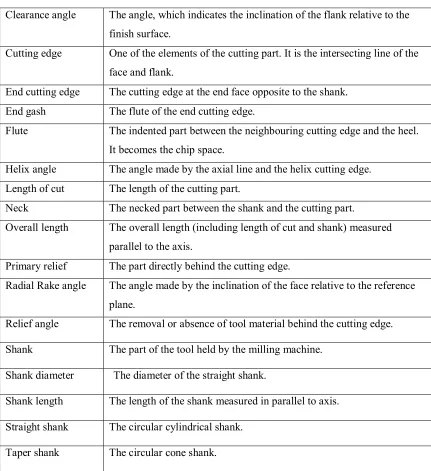
2.1 Terminology for End mill
Fig.3. Detailed Flute Form
Clearance angle The angle, which indicates the inclination of the flank relative to the finish surface.
Cutting edge One of the elements of the cutting part. It is the intersecting line of the face and flank.
End cutting edge The cutting edge at the end face opposite to the shank. End gash The flute of the end cutting edge.
Flute The indented part between the neighbouring cutting edge and the heel. It becomes the chip space.
Helix angle The angle made by the axial line and the helix cutting edge. Length of cut The length of the cutting part.
Neck The necked part between the shank and the cutting part.
Overall length The overall length (including length of cut and shank) measured parallel to the axis.
Primary relief The part directly behind the cutting edge.
Radial Rake angle The angle made by the inclination of the face relative to the reference plane.
Relief angle The removal or absence of tool material behind the cutting edge.
Shank The part of the tool held by the milling machine.
Shank diameter The diameter of the straight shank.
Shank length The length of the shank measured in parallel to axis.
Straight shank The circular cylindrical shank.
2.1.1 Direction of Helix & Hand
When an End mill is viewed from the shank side, the End mill having cutting edge face right is RIGHT HAND, and the End mill having cutting edge faced left is LEFT HAND. Both end mills have right helix type and left helix type, which makes 4 types in total.
F ig.4. Right-Hand Helix & Left-Hand Helix
The material and the shape of work piece should determine direction of hand and helix. Generally Type (A) is applied. In Case of Type (A) & (B), as cutting resistance force works to the teeth end direction, their shank used to have a thread, and in case of Type (C) & (D), as the cutting resistance force works to the shank end direction, their shanks used to be a taper with a tang. But currently, straight shank will do in any case due to the improvement of milling chucks.
The milling with Type (A) & (B) end mill is smooth as chips come up along the flutes. On the other hand, in milling with Type (C) & (D) surface finish of bottom face is rough and tool life is short, because chips go down toward work piece. Therefore these types are applicable only for special uses like drilling through holes or finishing cuts, in which chips do not cross over the marking-off line and burrs are not produced on the upper surface of work piece.
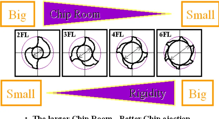
2.1.2 Number of Flutes
Number of flutes of end mills should be determined by milling materials, dimension of work piece and milling condition. Generally speaking, an end mill having small number of flutes and having big chip room is used for roughing cut and large number of flutes end mill is used for finishing cut.
The diagram below shows the differences of 2 flutes End mill to 6 flutes End mill, where the End mill is having less flute, the chip room is bigger and better chip ejection and End mill having more flutes, it is more rigid which will have lesser deflection and breakage.
Fig.6. Chip Room & Rigidity
2.1.3 End Cutting Edge
[image:16.595.131.504.229.432.2]There are Center Cut Type and Center Hole Type. The latter cannot be used for drilling, but is convenient for regrinding, while the former can be applied for any operation.
2.1.4 End Profile
End Style is divided into; Square End and Ball End. Corner radius, corner chamfer, corner round and drill nose can be gained by modification when regrinding, or by special order.
Fig.8. Various types of End Profile
2.2 Types of End mill
End mill cutters are probably the most commonly used of all the various types of cutters in the metal cutting industry. There are several different types of End mill available in the market and each individual type of End mill performs different functions and purposes.
The feature of 2 flutes End mill is designed with wide chip space, which is good for chips ejection and high-speed milling. It is normally used on conventional application, such as slotting, drilling and roughing purposes and the number of flutes should also be determined by the work material, dimensions of the work piece and milling conditions.
Fig.10. Multiple Flutes End mill
Multiple flutes End mills have several different types of design and features. For example, 3 flutes, 4 flutes and 6 flutes End mill and different number of flutes on the End mill cutters are cater for different cutting operations. In general, multiple flutes End mill is more rigid than 2 flutes End mill therefore it is normally used for side milling and finishing cut operations.
Ball Nose End mill is used for profiling and finishing operation of corner radius. This End mill is especially effective when milling curved surfaces and the lesser of the Ball Run out tolerance, the better the surface finishing of the work
materials.
Fig.12. Tapered End mill
Tapered End mill has a constant helix flute on all the length of cut therefore the radial rake angle is constant on all the length of cut, which provides excellent sharpness. It is used for taper process for which the work material has a tapered shape. The constant helix flute and the sharpness of the cutting edge provide a smooth surface finish.
Fig. 13. Roughing End mill
• Fine pitch for steel milling, cutting speed can be increased by 30-50% and tool life is over twice as long as course pitch.
• Coarse pitch is used for cast iron and aluminum alloy.
Fig.14. Roughing & Finishing End mill
This End mill is designed for roughing and removing large amounts of metal as well as getting a medium surface finish. It is designed with nicks on the peripheral teeth. These nicks are shifted by pitch/number of flutes and the crest is flat. This shape tool creates a better surface finish. Chips are small and fine and there is a smooth chip ejection. However, the required cutting force is higher than roughing End mills but still lower than conventional End mills. There are two main kinds of roughing and finishing End mills.
• TUF-nick (TFS): This roughing and finishing type End mill improves the surface finish and the tool life. During the finishing process the surface roughness is almost the same as the surface produced by a conventional End mill. When the surface finish tolerance is limited, TFS is the best.
2.3 Tool Material
The recent advancements in work materials are very remarkable, being developed are hard Chromium-Molybdenum steels, tool steels and heat resisting alloys to be used for parts of aircraft, engines, etc. On the other hand, there have been big developments in the machine tools, making operations more productive and economical with the presence of high-speed full automatic profiling machines, Numerical Control milling machines and machining centers. In order to meet the requirement of milling such a difficult to machine material, the improvement of tool materials is indispensable.
Selecting the proper cutting tool material increases productivity, improves quality and ultimately reduces costs. Many factors affect the decision of which material to use:
• Hardness and condition of the work piece material
• Rigidity of the tool, the machine and the work piece
• Production requirements
• Operating conditions such as cutting force, temperature and lubrication
• Tool cost per part machined (including initial tool cost, grinding cost, tool life, labour cost)
There are three important properties that must be considered when manufacturing end mills:
1. Hardness
• Hardness is the ability of a material to resist stresses and maintain hardness and cutting efficiency at elevated temperatures.
• Wear is the most common point of failure for cutting tools. Flank wear is directly related to speed and feed. As speed and feed are increased, rate of wear also increases.
• Toughness is the ability of the material to absorb energy and withstand plastic deformation without fracturing under a compressive load.
Fig.15. Various Tool Materials
2.3.1 High Speed Steel (HSS)
Table 1. Application on High Speed Steel
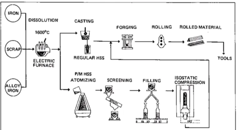
2.3.2 Particle Metallurgy High Speed Steel
Beside, H.S.S. Co. materials, there are also higher grade of end mills made of Particle Metallurgy H.S.S. These types of tool material are with better quality and made possible on the presence of high vanadium super H.S.S. end mills.
Fig.16. Manufacturing Process: Particle Metallurgy H.S.S. vs. Regular H.S.S.
Properties of Particle Metallurgy (HSS)
• Very fine and uniform size of carbides
• To get high and uniform hardness
• Excellent grind-ability makes the manufacturing easy
Fig.17. Microscope Photograph (Magnification: X400)
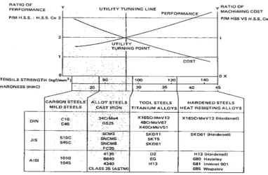
As the material is much more expensive, if it is used for milling mild materials, the user cannot enjoy the advantages of the Particle Metallurgy (HSS) end mills. In figure below, the ration of the performance of Particle Metallurgy (HSS) end mills to the same Conventional (HSS) end mills is indicated in the Y-axis left side, and the ratio of the machining cost of Particle Metallurgy end mills to the same of Conventional H.S.S. end mills is indicated in the Y-axis right side. Work material is shown in the X-axis.
ratio of performance is more than 2, we can make good use of Particle Metallurgy (HSS) end mills.
Fig.18. Performance vs. Machining Cost
Features of Particle Metallurgy H.S.S. End mills
• Rigid flute form to withstand heavy cutting torque
• High hardness for wear resistance
• High edge strength
• Shorter cutter sweep for higher rigidity (2 Flute)
Fig.19. Relative Toughness at Typical Working Hardness
2.3.3 Carbide Material
There is various type of carbide materials exist in the market and I will explain on the two most common types, which are the Tungsten Carbide (TC) and Micro-grain Carbide (MG).
Tungsten Carbide (TC)
Tungsten Carbide included in the material composition provides higher wear resistance and is generally used for insert type end mills and turning tools. There are four groups of carbide tools:
• Group P – for milling steels. If the work material produces longer chips, the tool must have high heat resistance. Tantal carbide (TaC) or Titanium carbide (TiC) is added in order to provide this heat resistance.
• Group M – this material performs in between P and K group
• Group Z – for micro-grain tools. Recommended for small size milling in order to prevent chipping or breakage, and to provide higher toughness. All groups have cobalt content.
Table 2. Carbide Classification
Micro Grain Carbide (MG)
Milling with normal tungsten carbide end mills is limited to high speed milling over 50 m/min and to the use only for aluminium alloys, cast iron, etc., because of lack of toughness. It cannot mill steels satisfactory. This fact requires an ideal mill, which can machine steels at a low surface speed, getting toughness and greater coherence (binding power) among grains to avoid material pullouts.
Micro-grain carbide is recommended for improving metal removal rates and tool life over those possible with high-speed steels for the condition where carbide with normal strength level would chip or break. The high edge strength of micro-grain carbide allows the use of high-speed steel tool geometry and when
Properties of Micro-grain Carbide
Micro-grain carbide has great toughness as well as wear-resistance and rigidity, which is as same as normal carbides. Its transverse rupture strength is 400 Kgf/mm2, which is almost the same as high-speed steel. Figure below shows the variation of feed when various end mills breaks. It certifies the toughness of MG end mills.
Fig.20. Properties of Carbide
Features of Micro-grain Carbide End mills
• Provided with sharp cutting edge with a special flute form best suited to cut steel (hardened and high alloy steel)
• Tolerances of both two-flute and four-flute types of end mills are standardized to “minus range”. Thus, there is no necessity to make adjustment of dimensions after replacing the tools
• Furthermore, the total length and shank diameter are provided especially for numerical control machining, eliminating the necessity of
measurement at each time of tool replacement.
• In addition to the features of excellent wear resistance and high rigidity, the Micro-grain with higher toughness is utilized.
3. Selection of Cutting Fluids
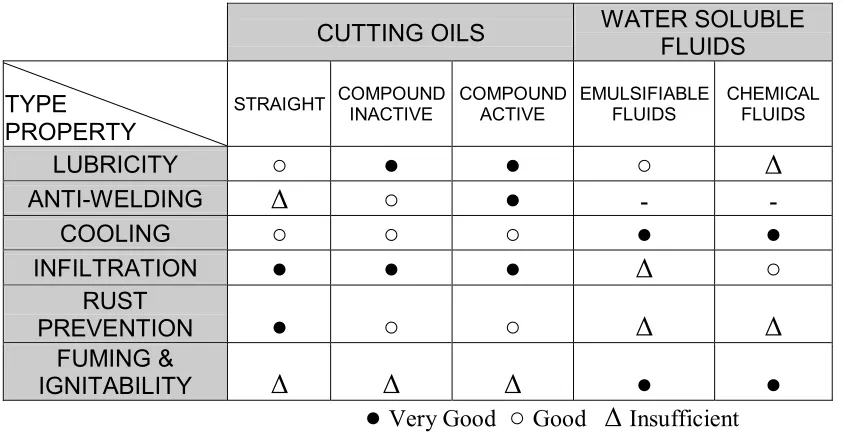
Milling process can be very complicated work and it significantly affect machined surface accuracy, tool life, cutting torque, etc. Different types of cutting fluids also affect it. Cutting fluids have basic three functions:
• Cooling
• Lubrication
• Anti-welding.
For the selection of cutting fluids, we must take the following three points into consideration:
• To make tool life longer
• To get better surface finish
• To get higher efficiency of operation
The table below shows the general properties of various cutting fluids.
CUTTING OILS WATER SOLUBLE FLUIDS
TYPE PROPERTY
STRAIGHT COMPOUND INACTIVE COMPOUND ACTIVE EMULSIFIABLE FLUIDS CHEMICAL FLUIDS
LUBRICITY
○
●
●
○
∆
ANTI-WELDING
∆
○
●
- -COOLING
○
○
○
●
●
INFILTRATION
●
●
●
∆
○
RUST
PREVENTION
●
○
○
∆
∆
FUMING &
IGNITABILITY
∆
∆
∆
●
●
[image:30.595.115.537.499.715.2]MILLED MATERIAL GENERAL RECOMMENDATION TO IMPROVE SURFACE FINISH TO IMPROVE PRODUCTIVITY TO IMPROVE TOOL LIFE POSSIBILITY OF USE OF
WATER SOLUBLE FLUIDS CARBON STEELS ALLOY STEELS Sulfur base-inactive (Sulfur 1-3%) Sulfur-chlorine base-active (active
sulfur under 2%)
Sulfur base-inactive (Chlorine 5-10%) Emulsifiable (Dilution 1:10) STAINLESS STEELS HEAT RESISTING STEELS Sulfur-chlorine base-active (base-active sulfur under 2%)
(Chlorine-under 5%)
Sulfur-chlorine base-active (active 2-5%) (Chlorine
1-5%)
Sulfur-chlorine base-active (active sulfur under 2%)
(Chlorine 5-10%)
Impossible CAST IRON DRY
ALUMINIUM ALLOYS
Straight cutting oil (fat 5-10%)
Sulfur-chlorine base-active (active sulfur under 2%) (Chlorine under 5%)
COPPER
ALLOYS Straight cutting oil (fat 5-10%) Chlorine base-inactive (chlorine 1-3%)
Emulsifiable (Dilution 1:10) THERMO SETTING PLASTICS (Bakelite, Epoxy) Dry Impossible THERMO PLASTICS (Poly carbonite, Vinyl chloride)
Straight cutting oil (fat 5-10%)
________
Water
Table 4. Recommendation Chart for Cutting Fluids
The influence of Cutting Fluids on Micro-grain Carbide End mills
[image:31.595.121.544.71.364.2]Micro-grain carbide contains more cobalt than normal carbides to get higher toughness, but when cutting steels, cooling by cutting fluids is required, in order to avoid material pull outs. Below chart is the milling test result on 2 flutes micro-grain carbide end mill with cutting fluids and without cutting fluids performances.
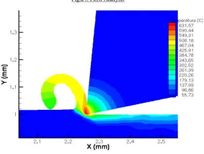
4. Surface Treatment
Metal cutting tools are often given surface treatments to improve tool
performance and longevity. As cutting tools cut on material, it will generate heat, welding of material chips onto cutting tools, friction and wear off of cutting tools etc. Therefore appropriate types of coating are required to prevent all these problems.
[image:32.595.118.529.366.676.2]The below diagram is the FEM analysis of heat generated when cutting tools cut on material.
The table below shows the purpose and applications on various surface treatments:
TYPE CHARACTERISTICS PURPOSE APPLICATION
STEAM OXIDE
* Fe3O4 film
* Retain coolant with porous surface
* Reduce friction * Prevent welding
Anti-welding Soft and ductile steel Stainless steel not suitable for
aluminium
NITRIDE
* Treated thickness 30 ~ 50 µm * Surface hardness 1000 ~ 1300 Hv
Increase Wear resistance
High tensile steel Cast Iron Aluminium die casting
TiN Coating * Treated thickness 2 ~ 3 µm * Surface hardness 2000 Hv
Anti-welding Reduce of
friction Wear resistance
High tensile steel Stainless steel Heat resistance steel
Titanium alloy
TiCN Coating
* Treated thickness 3 ~ 6 µm * Surface hardness 2700 Hv
* Wear resistance
* Friction coefficients 30% less than TiN
Anti-welding Thermal resistance Wear resistance
Dry high speed cutting Long tool life High speed cutting Suitable for HSS tools
TiALN Coating
* Treated thickness 2 ~ 6 µm * Surface hardness 2800 Hv
Thermal resistance High wear resistance Hard materials Abrasive materials High speed cutting Suitable for carbide
[image:33.595.118.534.153.450.2]tools
The table below shows the various coating features and applications
Coating Colour Hardness (HV) Coefficient Friction Oxidation Point Adhesion Features Applications
TiN Gold 2,000 0.4 500°C (932°F) ● High adhesion with HSS Available for cutting conventional steels. For aluminium alloy, effective under high speed chatting
TiC Purple Red- 3,000 0.2 300°C (572°F) ∆
High hardness but low heat resistanc e. High adhesion with carbide For tungsten carbide tools
TiCN Purple Gray- 2,700 0.3 400°C (752°F) ○
Better adhesion resistanc
e due to higher hardness & lower friction coefficie nt than TiN Effective for cutting steels & superior to TiN on high speed cutting
TiALN Purple Gray- 2,800 0.3 (1292°F) 700°C ○
• Steam Oxidizing:
This process produces a film on the surface of the drill, as the tools are heated in a steam furnace for 30 to 60 minutes at 500 to 550 º C (932 – 1040 º F). The
benefits of this treatment include reduced heat from friction and improved welding and build up prevention.
Steam oxidizing is therefore most effective for milling low carbon steel or stainless steel (known for often causing welded).
• Nitride:
The nitride process produces a surface that is harder than regularly heat-treated (HSS) End mills are submerged in a cyanide salt bath of 500 to 560 º C (932 – 1040 º F) for a specific period of time (30 ~ 90 min). Nitride End mills exhibit improved lubricant retention properties, which ultimately reduce galling and metal pickup. The benefits of using a nitride-coated tool are:
• High surface hardness
• High wear resistance
• High heat resistance
• High corrosion resistance
Coating Operations
CVD:
temperature (950 ~ 1065 º C, 1742 ~ 1949 º F), which dissociates the reactive gases, causing the desired coating compound to form on the tool surface. CVD exceeds the tempering temperature of (HSS).
The high temperature of the CVD process makes it somewhat less popular than the PVD method. CVD coating also tends to be somewhat thicker (0.008mm) than PVD produced coating (0.003mm).
PVD:
The PVD process relies on ion bombardment instead of high temperatures (260 ~ 485 º C, 500 ~ 905 º F). The reactive ion plating involves the ionization of
vaporized “target material”, such as titanium, in the presence of the reactive gas (N2 for TiN coating) again with electrical potential applied to accelerate the TiN ions towards the tool.
The initial investment in equipment for PVD coating machines is three to four times greater than for CVD machines, but the PVD process cycle time can be 10 times faster than CVD. The diagram below shows on the PVD process.
• Titanium Nitride (TiN):
Rapid developments in machine technology increase the demand for faster and more efficient operations. The popularity of unmanned and automated operations is increasing around the world. Surface coating, first introduced in 1980, greatly improved the capabilities of machinery tools. Coated products quickly dominated the market, and today, TiN coating is the most popular treatment for precision tools.
TiN coated tools reduce the contact length at the chip-tool interface thereby reducing tool temperatures and adhesions wear near the cutting edge. Today cutting tools are coated with titanium nitride and titanium carbide by the two previously mentioned methods:
• Chemical Vapor Deposition (CVD)
• Physical Vapor Deposition (PVD)
Tools coated with TiN have surface hardness that is about three times harder than un-coated HSS tools. TiCN is fast becoming one of the most advantages coatings for H.S.S. cutting tools, but TiN coated tools are still applicable to a broader range of operations.
The benefits of TiN Coating on HSS:
Properties of TiN:
Hardness considerable exceeds that of high-speed steel.
• TiN offers a low coefficient of friction.
• TiN possesses high chemical stability and is extremely resistant to corrosion.
• TiN resists adhesion, welding and galling, even at elevated temperatures.
• TiN allows for increases in speeds and feeds.
• Titanium Carbide Nitride (TiCN):
TiCN is the most recent development in coating innovation, and will most likely become the dominant coating used in the industry.
It is now believed that increased hardness is achieved when nitrogen is partially substituted for carbon in titanium carbide. The titanium carbon nitride offers a compromise between the high hardness of the carbide (2700 HV versus 2000 HV for nitride) and the superior thermo chemical stability and anti-seizure properties of nitride.
• Titanium Aluminum Nitride (TiALN):
It is clear that no universal coating exists for all kinds of cutting processes. For example, TiCN was designed to reduce abrasive wear, while TiALN lowers the oxidation wear. TiALN is harder than TiCN or TiN, and also has superior heat resistance. The temperature of oxidation is high, which is good for milling high- hardened steel and for high cutting speeds. The adhesion of the coating on the HSS tool is, however, significantly weaker.
The diagram below shows the performances of various coating. It stated clearly that TiALN is the most suitable coating for End mills to operate at high-speed milling.
5. Selection of work materials
In metal cutting industries today, innumerable kinds of material are handled and their characteristics are various. In addition, a same material may have difference properties through different heat treatment and so on.
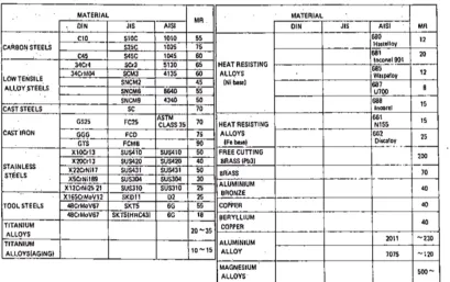
There is not a generally acknowledged or expression of “MACHINABILITY”, the degree of ease with which a particular material can be machined. But, Machinability Rating is known as a mean of quantitative expression of machinability.
[image:40.595.127.536.472.729.2]MR (Machinability Rating) is the value of cutting speed (V60) of a material (AISI 1112 steel = 100), which is measured when the tool life become 60 minutes. A large figure of MR means to be milled at higher speed in a same tool life or to get longer tool life at a same cutting speed.
This machinability rating of a given work material changes with the type of operation involved and with the tool material selected. In addition, for the same MR value materials, if their properties not the same, different type of tool and different cutting conditions are recommended. The application of the machining rate should be restricted to very special situations where the ratings have
meaningful and consistent value.
• Structural Steels
Structural steels are divided into two types, Carbon Steels and Alloy Steels. When annealed, 0.25% carbon containing steel has best machinability, when they
contain effective alloying elements, among which Nickel affects the
machinability most. In case of low-alloy steels, machinability is worse, when the Nickel percentage is 2%, while phosphorus, sulfur and lead improve
machinability. Vanadium affects nothing within the usual percentage.
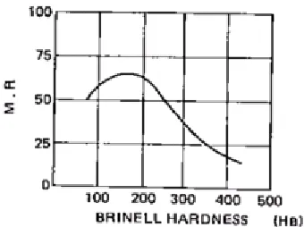
[image:41.595.236.406.546.673.2]Machinability of structural steels has strong relationship with the hardness given by heat treatment.
• Stainless Steels
Stainless steels are most difficult to cut than structural steels due to the following reasons.
• Tensile strength is higher
• Easy to weld
• It is more work hardening
Austenite stainless steels (18-8, 25-20) have the above-mentioned properties much and low machinability. Martensite stainless steels (13Cr) have similar properties to low carbon alloy steels, but they need higher driving power for milling. Ferrite stainless steels are a little brittle and the styles of chips are
produced in pieces. But when they contain high chromium, the chips are produced in coil shape as austenite stainless steels.
Precipitation hardening stainless steel (17-4PH) are difficult to cut same as
austenite stainless steels, Particularly refined one has extremely low machinability like heat resisting alloys.
• Alloy Tool Steels
similar to high carbon structural alloy steels and making cutting tools wear easily with their double carbides.
Among alloy tool steels, one for impact working, containing low carbon (DIN 35WcrV17, JIS SKS41, AISI S1, etc.) and for cutting, containing few alloying elements (DIN 142WV13, JIS SKS11, AISI F2 etc.) is comparatively easy to be cut. On the other hand, cold forming die steels (DIN X165CrMoV12, JIS SKD11, AISI D2) have large carbide and are difficult to be machined. Hot forming die steels (DIN X40CrMoV51, JIS SKD61, AISI H13) are used after refining, and are difficult to be cut.
• Cast Iron
As cast iron is produced in various complicated forms by casting process without any mechanical operation, its tensile strength and toughness are very low. Ductile cast iron, malleable cast iron and nodular cast iron have improved mechanical properties.
The machinability of malleable cast iron is good. For hard materials, use low milling speed and Nodular cast iron is easier to cut than gray cast iron.
Fig.28. Relation between Tool life and Work hardness
• Copper & Copper Alloys
Lead containing free cutting brass, free cutting bronze and free cutting
phosphorus bronze are able to cut at high speed and fast feed. On the other hand, copper, plain bronze, phosphorus bronze, aluminum bronze and Beryllium copper are mild, and make the tool wear easily.
•
Aluminium AlloysAluminium alloys do not have high strength a cast or annealed, but they have high strength through working. For example, cold working for precipitation hardening type and heat treatment for aging hardening type.
Precipitation hardening aluminium alloys are mild and easily affected by work hardening. Cold wrought ones are a little machinable, aging hardening aluminium alloys are cut to be good surface finish with or without cutting fluids. Refined one is easier to be cut than annealed one.
High-speed milling is possible and the limit of speed is determined by the work piece caused by the lack of rigidity of tools. Length of cut can be increased to the limit of the strength of work piece, holding strength of tools, machine tools power and chip ejection. Feed can be also increased to the limit of surface roughness and rigidity.
• Magnesium Alloys
Machinability of magnesium alloys is good and chips are produced in the form of fragments, which results in high efficiency milling. Surface finish is also good without any relation to presence of cutting fluids or milling speed.
• Titanium Alloys
Titanium alloys have following characteristics during milling.
• It acts upon the components like oxygen and nitrogen in tool material at high temperature. It may cause wear and galling during cutting.
Kgf/mm, refined: 100 Kgf/mm) make the contact press high, resulting in high temperature at cutting edge.
• Thermal conductivity is comparatively low, which makes the temperature at cutting edge high.
• As modulus of elasticity is comparatively low. Clamping press and cutting force easily deform it.
Surface finish is comparatively good. Work hardening is little therefore much cutting force is not necessary. But high-grade tool material (Particle Metallurgy H.S.S.) should be used and the cutting fluids containing halogen elements like chlorine must not be applied, because they may corrode work piece.
• Heat Resisting Alloys
Heat resisting alloys are one of the most difficult to machine materials. Their characteristics are as follows.
• High shearing strength causes high cutting resistance.
• Work hardening
• Contains hard chemical compound, which makes the tool wear easily
• As thermal conductivity is low, heat is apt to concentrate at the cutting edge.
excessive slow feed is not recommended in order to prevent the work piece from work hardening.
Fig.29. Milling test on Inconel material
5.1 Guide for milling difficult to machine materials
! Ductile and High Tensile Materials
Austenite stainless steels, Titanium alloys and heat resisting alloys
• In case of short length of cut or slow feed, the surface hardened by pervious tooth cut (work hardening) is milled once again by next tooth. If a tooth cannot bite easily and slides out the surface, which will result in short tool life. For milling heat-resisting alloys, as short length of cut is not permitted, even if they are difficult to machine, extremely low milling speed must be applied.
• For good chip ejection, sharp cutting edge and large clearance angle is indispensable. On the other hand, this weak cutting edge is recovered by the rigidity of machine tools. Re-sharpening in early stage is recommended, because dull teeth increases cutting torque, hardening work piece surface and produce built-up edge, resulting in damage to tools.
• Feeding must be automatic and must not stop during operation. If it does, it may cause work hardening of work piece.
• Cutting fluids should flow strongly to the cutting portion, in order to push out chips and help cooling.
! Hard Steels
Hot forming die steels (over HRC 35)
• Select as large size mill as possible to get high rigidity
• Use strong and rigid machine tools and tooling in order to avoid vibration
• Use high-grade tool materials like Particle Metallurgy H.S.S.
• Cutting speed and feed should be slow in inverse proportion to the hardness of work piece
6. Cutting Conditions
The factors to determine the cutting condition are:
• Material to be milled
• Surface finish required
• Depth of Cut
• Tool life
The combination of these factors determines the revolution and the feed. As the revolution and the depth of cut are in mutual relationship, which is the change of one makes the other change.
Fig.30. Inter-Relationship of three factors REVOLUTION
• Revolution
Revolution is the most important factor to determine the tool life. Generally, it depends on the material to be milled. The below are the various cutting condition formulas to calculate cutting speed and spindle speed.
Formulas for Square End mill:
Vc =
Π
x Dc x N / 1000
N = Vc x 1000 /
Π
x Dc
Vc: Cutting Speed (m/min) Dc: Diameter of Tool (mm)
N: Spindle Speed (rpm)
Π: 3.142
For milling with long length of cut, lower milling speed is recommended, as it is apt to deflect and chatter. Refer to Table.
Material Type Mild Steels (~50 kgf/mm2) Brass, Copper Medium Tensile Steels (50~80 kgf/mm2) Mild Steel Forgings Cast Iron, Hard Brass Bronze, Copper High Tensile Steels (80~100 kgf/mm2) Unalloyed Titanium Heat Resistant Ferritic Low Alloys High Tensile Steels (100~180kgf /mm2) Tool Steels Medium Strength Stainless Steels Heat Resistant High Alloys High Strength Titanium Alloys High Strength Stainless Steels Aluminium Alloyed Aluminium Plastics Woods
Short 35 ~ 45 28 ~ 33 15 ~ 20 10 ~ 15 5 ~ 10 80 ~ 120
Long 20 ~ 30 15 ~ 25 10 ~ 15 8 ~ 12 3 ~ 8 50 ~ 80
Table 8. General Recommendation for Cutting Speed (HSS-Co)
detail information, please refer to the recommended milling conditions data attached.
Formulas for Ball Nose End mill:
Ve =
Π
x De x N / 1000
De = 2 Sqt [Ap (Dc – Ap)]
Vf = N x Fz x Zn
N = Ve x 1000 /
Π
xDc
Ve: Effective Cutting Speed (m/min) Vf: Table Feed (mm/min)
N: Spindle Speed (rpm)
De: Effective Cutting Diameter (mm) Dc: Diameter of Tool (mm)
Zn: Number of Teeth
Π: 3.142
• Feed
Feed is the most important factor for the productivity. The recommendation of feed is affected by the material to be milled, tool material and depth of cut, while the tool life is respected.
The formulas below are to calculate table feed and various effective feed per tooth.
Vf = N x Fz(eff) x Zn
Vf: Table Feed (mm/min)
N: Spindle Speed (rpm)
Fz(eff): Effective Feed per Tooth (mm/teeth)
Effective Feed per Tooth Fz(eff) for Roughing / Semi Finishing
Fz(eff) = 0.5 x Fz
Fz: Feed per Tooth (mm/teeth)
Fz(eff) = 1.0 x Fz
For Harden Steel (Above HRC 40) Ap = 0.05 x Dc
Ae = 1.00 x Dc
Fz(eff) = 2.0 x Fz
For Harden Steel (Above HRC 40) Ap = 1.00 x Dc
Effective Feed per Tooth Fz(eff) for Finishing
Fz(eff) = 2.0 x Fz
Ap = 1.50 x Dc Ae = 0.10 x Dc
For Harden Steel (Above HRC 40) Ap = 1.00 x Dc
Ae = 0.02 x Dc
Fz(eff)
=
1.0
x
Fz
Ap = 1.00 x Dc Ae = 0.20 x Dc
For Harden Steel (Above HRC 40) Ap = 0.70 x Dc
Feed per tooth, Fz (mm/teeth)
Material
Cutting
Speed ∅ 3 ∅ 4 ∅ 5 ∅ 6 ∅ 8 ∅ 10
General Steels (< HRC 20)
70 - 85 0.010-0.030 0.015-0.030 0.020-0.045 0.025-0.050 0.030-0.070 0.040-0.090
Alloy Steels (HRC 20 -
30)
45 - 60 0.010-0.030 0.015-0.035 0.020-0.045 0.025-0.050 0.030-0.070 0.040-0.090
Alloy Steels (HRC 30 -
40)
30 - 45 0.010-0.020 0.015-0.035 0.015-0.045 0.025-0.050 0.025-0.070 0.035-0.080
High Alloy Steels (< HRC 40)
20 - 35 0.005-0.015 0.008-0.020 0.010-0.020 0.012-0.030 0.015-0.035 0.020-0.045
Cast Iron 60 - 75 0.010-0.035 0.020-0.050 0.030-0.065 0.030-0.080 0.060-0.100 0.070-0.160
Stainless Steels / Titanium
Alloys
45 - 60 0.005-0.010 0.008-0.018 0.010-0.023 0.012-0.030 0.015-0.035 0.020-0.045
Aluminium
[image:54.595.114.490.97.362.2]alloys 180 - 220 0.010-0.030 0.015-0.035 0.020-0.045 0.025-0.050 0.030-0.070 0.040-0.090
Table 9. Feed per tooth on Square End mill
Feed per tooth, Fz (mm/teeth)
Material
Cutting
Speed ∅ 3 ∅ 4 ∅ 5 ∅ 6 ∅ 8 ∅ 10
General Steels (< HRC 20)
35-50 0.010-0.020 0.015-0.025 0.025-0.035 0.030-0.040 0.040-0.050 0.045-0.055
Alloy Steels (HRC 20 -
30)
25-40 0.010-0.020 0.015-0.025 0.025-0.035 0.030-0.040 0.040-0.050 0.045-0.055
Alloy Steels (HRC 30 -
40)
15-30 0.050-0.015 0.010-0.020 0.012-0.030 0.015-0.030 0.020-0.035 0.025-0.040
Cast Iron 40-60 0.010-0.020 0.015-0.030 0.020-0.040 0.025-0.045 0.035-0.055 0.045-0.070
Stainless Steels / Titanium
Alloys
35-50 0.005-0.015 0.010-0.020 0.012-0.030 0.015-0.030 0.020-0.035 0.025-0.040
Aluminium
alloys 160-200 0.015-0.025 0.020-0.035 0.025-0.050 0.030-0.065 0.040-0.080 0.055-0.100
[image:54.595.114.489.451.672.2]a) Relation of Feed per tooth to milled material
Figures below show the best feed per tooth varies with the change of milled materials.
FEED PER TOOTH & MILLED MATERIALS
END MILL: EDS-DIN327 φ 6mm (2 Flutes)
MILLED MATERIAL: DIN C45
JIS S45C
AISI 1045
HARDNESS: HRB 94-96
SPEED: 33 m/min (1,750 rpm)
DEPTH OF CUT: 3 mm (Slotting)
CUTTING FLUID: Sulfo-Chlorinated Oil
END MILL: EDS-DIN327 φ 6mm (2 Flutes)
MILLED MATERIAL: DIN X40CrMoV51
JIS SKD61
AISI H13
HARDNESS: HRC 40
SPEED: 8.5m/min (450 rpm)
DEPTH OF CUT: 3 mm (Slotting)
CUTTING FLUID: Sulfo-Chlorinated Oil
LIMIT OF WEAR LAND: 0.4mm
Table 11. Feed per tooth for Mild Steel & Hard Steel
Table above shows adequate feed per tooth for mild steel and hard steel.
MILLED MATERIALS
Mild Steel: DIN C45
JIS S45C
AISI 1045
Hard Steel: DIN X40CrMoV51
JIS SKD61
AISI H13
MILLED CONDITIONS
b) Relation of Tool material to Feed per tooth
Feed per tooth should alter according to tool materials, namely, High Speed Steel and Tungsten Carbide.
It is very important to select the feed not to cause chipping, particularly in milling of hard materials (over HRC 40). Milling data below indicates the tool life varies very markedly when the feed is changes in both of Carbide end mills and particle metallurgy H.S.S. end mills.
Fig.31. Milling Data
MILLING CONDITION
End Mill: MG-EDS φ 6mm (2 Flutes)
CPM-EDS φ 6mm (2 Flutes) HARDNESS OF MILLED
Material: HRC 44-45
Speed: 14.5m/min (770 rpm)
Depth of Cut: 6mm (Slotting)
Cutting Fluid: Sulfo-Chlorinated Oil
c) Relation of Depth of cut to Feed per tooth
Feed per tooth should vary with the change of depth of cut, too.
In slotting operation, our recommendation chart picks up 1/2D (a half mill diameter) for depth of cut. If it is increased to 1D, feed is decreased to 50%, but even if it is decreased to 1/4D, feed must not be increased to double. 30% increase will be the maximum because there is limit to the strength of cutting edge and it may cause chipping. To get higher productivity selecting larger number of flute end mills is recommended, in case of small depth of cut.
In side cutting, our recommendation chart picks up 1.5D x 0.1 D (axial depth and radial depth) for depth of cut. If the radial depth is changed to 0.3D, feed should be decreased 50% and in case of under 0.05D radial depth of cut like finishing operation. For example, it produces better surface finish to increase revolution 20 – 30% than to increase feed same percentage. In general, decreasing feed
7. Re-Sharpening and Inspection
7.1 Case of Re-Sharpening
When the product finish becomes worse, the cutting edge must get dulled, chips become smaller and the cutting sound gets louder. In such cases, an End mill must be sharpened. The following are the damages of End mills when the
re-sharpening is required.
Fig .32. Damages of Cutting Edge
The wear on primary land is seen often and re-sharpening the primary land makes the End mill perform almost the same as new one. The width of the wear land develops very fast after a time period of use, resulting in rough surface finish and chipping. Re-sharpening must be done before it occurs. In general, when the width of wear land become 0.2 ~ 0.4 mm (in case of roughing End mill: 0.5 mm) re-sharpening is required.
7.2 How to Re-Sharpen Primary Land
There are three types of re-sharpening according to three types of primary relief. Hereafter, we show to re-sharpen eccentric relief, which is superior both in cutting edge strength, surface finish and tool life.
[image:60.595.242.386.215.322.2]Fig.34. Relation between Wear Land & Length of Milling
Fig.35. Three types of Primary Relief
7.2.1 The Principle of Eccentric Relief
When an End mill and a wheel are set up as per Figure 36 and the wheel is advanced to the radial direction, in the section X-X, the top of the End mill’s cutting edge (a) is on the high side of the wheel. A tooth rest
Fig.36. Eccentric Relieving
At this section, the top of the cutting edge is positioned lower than the tangent line of the wheel. Therefore, point (a’) is ground in lower position than point (a) by aa’ tan α.
Fig.37. Enlarged View
In relation to the eccentric relief, the following formula is made up.
θ: Helix angle of End mill
β: Primary relief angle
And when the checking distance is x and the relief amount (drop) is y, the following formula are made up.
α: Angle of wheel inclination D: Mill diameter
A helical tooth is required to generate eccentric relief, theoretically any helix angle, but actually the helix must be more than 15 degree to be successful.
7.2.2 How to Re-Sharpen (re-sharpening order)
1) Setting
Hold an End mill between the centers freely enough to rotate, parallel to the axis of a grinding wheel. If the End mill does not have a center hole, hold it by its shank.
Fig.38. Holding End mill
2) Selection of a Wheel & Dressing
Recommended wheel is alundum type and about 120 mm diameter cup type. The wheel is 2 or 3 times as wide as axially measured primary land width. The wheel is dressed parallel to the axis or wheel by a diamond dresser.
3) Angle of Wheel inclination
[image:64.595.231.448.462.693.2]The wheel is positioned with its axis at a slight angle to the cutter axis and changing the angle of wheel inclination varies the degree of relief.
Fig.41. Wheel Inclination
4) To set tooth rest
The high point of the tooth rest must contact the tooth face at the high side of the wheel and be the same height as the wheel and work centers, but as usual End mills have a positive rake angle, the high point of the tooth rest is positioned a little higher than the height of the wheel and work centre.
Fig.42. Position of wheel, End mill and tooth rest
5) Trial Grinding
Fig.43. Trial Grinding
6) Checking Eccentric relief & adjustment of height of tooth rest
Watch the primary relief after trial grinding, to check that the reflection light or primary relief surface is parallel to axis of the End mill. If the reflection is not correct, adjust the height of tooth rest. (See Figure 44)
Fig.44. Check of Eccentric Relief
[image:66.595.241.425.425.610.2]7) Grinding
[image:67.595.250.455.596.705.2]Grind the primary relief until all of the wear has been removed, taking care to avoid excessive diameter loss and burring. The amount of stock removed is 0.01mm per pass. (Roughing: 0.2mm) Light finishing cuts are required to produce smooth cutting face.
Fig.45. Grinding Primary Relief
8) Removing Burrs
The grinding will produce burrs on the cutting edge. The burrs are removed, soon after milling is started. But, if good surface finish is required, they must be removed, an acrylic or aluminium plate is softly touched along the helical teeth.
Fig.46. Removing Burrs
without any other set-up change, and grind the secondary clearance face to concave form. In grinding should be done before primary relief grinding.
Fig.47. Grinding Secondary Clearance
7.2.3 Regrinding Cutting Face
Slight grinding will do, removing welded materials in case of regrinding cutting face of finishing End mills. But, in roughing End mills, as it is not re-sharpened on primary relief, cutting face must be reground until wear land on primary relief is completely removed. Generally recommended cutting angle is 12 degree – 18 degree.
• To hold End mill
The End mill mounts on the table perpendicular to axis wheel and hold it between centers concentric but loosely enough to rotate, as primary relief grinding holding between centers is better.
• Selection of wheel and dressing
[image:69.595.251.414.620.745.2]Use alundum type, 100 – 130 diameter and saucer type wheel. Dress the wheel with diamond dresser carefully not to make radial run-out.
Fig.49. Dressing
• Angle of Wheel Inclination
The angle of wheel inclination should be 1 degree – 3 degree larger than the helix angle of the End mill to make a slight clearance between the End mill’s cutting face and the wheel.
• Adjustment of Offset
Adjust offset amount to make wheel face have contact with whole cutting face of the End mills (from cutting edge to bottom of flute). Increase offset, when the wheel contacts cutting edge side only (cutting angle gets smaller), and reduce offset, when the wheel contacts bottom of flute only (cutting angle gets longer).
Fig.51. Adjustment of Offset
• Grinding
Grind the cutting face from shank side forward cutting end, having a soft contact to cutting face. The feed of the wheel must be as slow and constant as possible, because it affects the surface roughness of cutting face.
Particularly when the wheel passes through the end of mill, help the rotation of End mill by hand, carefully not to make the cutting edge dull.
7.2.4 Re-Sharpening End mill
Primary land is first to be re-sharpened and the necessity of re-sharpened secondary clearance face and end gash depends on seriousness of
damages. In any cases, indexing equipment is required.
• Sharpening Primary Land
Set up an End mill and a cup wheel as per Figure 53. The End mill is set inclined at the angle of axial primary relief and end cutting edge
concavity. Table 13 indicates usual degree of the mentioned two angles. For the End mill only for drilling, the angle should be 8 degree – 12 degree.
[image:71.595.277.426.382.561.2]Fig.53. Grinding of End Primary Relief
• Re-Sharpening End Gas
When the removed amount of regrinding on end primary land is big, it becomes wide and chip room becomes smaller. In such case, the end gash should be re-sharpened by cup type wheel, setting the End mill inclined at gash angle.
[image:72.595.224.439.393.510.2]Fig.54. Comparison of before & after Gash grinding
Fig.55. Re-Sharpening Gash
7.2.5 Inspection
Although the regrinding is done, if the specifications are changed, the milling performance as a new End mill cannot be regrind and the regrinding work is evaluated as wasted.
Followings are necessary checking points. 1) Primary relief angle
3) Radial run-out of peripheral teeth and axial run-out of end teeth
4) Surface roughness
• Inspection of Primary Relief Angle
After confirming the primary relief is eccentric, the primary relief angle must be checked. The angle is calculated by using the formula given above. But as it is too much work, it is better to apply the procedure to check with indicators.
Fig.56. Indicator Set-Up for checking Radial Relief
Procedure to Check Radial Relief Angles with Indicators. 1) Mount the cutter to rotate freely with no end movement. 2) Adjust the sharp pointed indicator to bear at the very tip of
the cutting edge, pointing in a radial line, shown in Fig 56. 3) Roll the cutter on the tabulated amount given under
4) Consult for amount of drop for the particular diameter and relief angle.
• Inspection of Cutting Angle
To measure the cutting angle, the procedure using indicators as Figure 57 shows is easy. Measuring the indicator drop (y) within the checking distance (x), consult table 14.
[image:74.595.265.440.378.516.2]Since the cutting face is hook form, it is better to measure twice at different checking distance and to get the average. Generally the checking distance is MILL DIAMETER x 0.025.
Table 14. Cutting Angle and Indicator Drop (mm)
• Inspection of Cutter Run-outs
A cutter performs best when the cutting edge of all teeth runs true with the axis. Then each tooth does its share of work. Radial and axial run-outs should be checked with an indicator after each sharpening. Put an End mill on a Vee block and measure run-outs of peripheral teeth and end teeth with indicators, rotating the End mill.
Fig.58. Measuring Cutter Run-outs
Table 15. Tolerance of Cutting Run-outs
• Surface Roughness
8. Machining problems in Conventional End mills
Normally when production workers using conventional End mills to perform on certain machining jobs, they will face with some common milling problems.
Some of the problems:
• Different End mills use for different applications
! Result in higher tooling cost
! Longer machining time and cost
• Improper selection of End mills
! Result in poor quality milling and damage work material
! Cause tool breakage which will also affect milling machine capacity
• Unable to achieve high speed milling and cutting process
! Not using high speed CNC machining centre
! Using conventional End mills
8.1 Troubleshooting
Guides
SPECIFIC
PROBLEM CAUSE SOLUTION
Feed too fast Slow down to proper feed Feed too fast on first cut Slow down on first bite Not enough rigidity of Machine tool
& Holder Change rigid machine tool or holder Loose hold (tool) Correct to tight holding
Chipping
Teeth too sharp Change weaker cutting angle, primary relief
Speed too fast Slow down, use enough coolant Hard material Use higher grade tool material, add
surface treatment
Biting chips Change feed & speed to change chip size or clear chips with coolant or air blow
Improper feed & speed (too slow) Increase feed & speed and try down cut Improper cutting angle Change to correct cutting angle Wear
Too small primary relief angle Change to larger relief angle Feed too fast Slow down feed
Too large cutting amount Make smaller cutting amount per teeth Breakage
Too long flute length or long overall
length Hold shank deeper, use shorter end mill Feed & speed too fast Correct feed & speed
Not enough rigidity (Machine &
Holder) Use better machine tool or holder or change condition Too much relief angle Change to smaller relief angle, put
margin (touch primary with oil stone) Cutting too deep Correct to smaller cutting
Chattering
Too long flute or long overall length Hold shank deeper, use shorter end mill or try down cut
Too much cutting friction Regrind at earlier stage Tough work material Apply premium tool Short tool life (dull
teeth)
Improper cutting angle Change cutting angle & primary relief Too much cutting amount Adjust feed or speed
Not enough chip room Use less number of flute end mill Chip packing
Not enough coolant Apply more coolant or use air blow Feed too fast Slow down to correct feed
Too much wear Regrind at earlier stage Chip biting Cut less amount Rough surface finish
No end teeth concavity Put concave on bottom teeth Too much wear on primary relief Regrind at earlier stage Incorrect condition Correct milling condition Burr
Improper cutting angle Change to correct cutting angle Too tough condition Change to easier condition No dimensional
accuracy Lack of accuracy (Machine &
Holder) Repair machine or holder Feed too fast Slow down to correct feed Too much cutting amount Make less cutting amount Too long flute length or long overall
length
Use correct length tool & hold shank deeper
No-perpendicular side
9. Safety Procedures
Designing features on Multi Purpose Carbide End mill for user friendly
During my designing stage, I have to take note on certain areas that will not cause any injuries to the operators while using my multi purpose Carbide End mill.
• Handling of the End mill cutter
Problem: - As the cutting edge of the End mill cutter is very sharp and if the operators did not handle it with care or without safety protection (safety gloves), they will cut their hand very easily.
Solution: - Add in a corner protection chamfering at the tip of the cutting edge will minimize the operators to cut their hands accidentally and the End mill cutter will still be sharp enough to perform an excellent surface finishing quality. On top of that, operators must also always remember to put on safety gloves.
• Work material chips produced by End mill cutter
Problem: - Normal work material chips produced by conventional End mill cutters are long and curly, which can get tangled in the spindle or the work material. Operators will have to manually remove it by hands.
• Distortion and Vibration of the End mill cutter.
Problem: - While using multi purpose Carbide End mill cutter, it causes vibration and distortion of the milling machine, which will spoil the work material and also cause injuries to the operators.
Solution: - Operators using the multi purpose Carbide End mill need to have proper technical guidance on how to use it by informing them the accurate cutting speed and feed rate. Suitable tool chuck holder should also be introduced to hold the End mill cutter tightly and rigidly, in order to prevent distortion or vibration and unnecessary injuries to the operators.
Safety issue to take note while using cutting tools
1. Don’t use tools in the inappropriate cutting condition
• Utilize the recommended cutting conditions just as general guide, when starting operation. It is necessary to adjust cutting condition when an unusual vibration, different sound occur by cutting.
2. Don’t use tools with considerable wear or cracks
• Wear or cracks in the tools cause breakage. Be sure that there is no wear, no cracks before using tools.
3. Don’t use tools by the reverse rotation
4. Attach tools firmly to the holders to prevent shaking
• Insufficient retention of tools causes breakage. Confirm that tools are attached firmly to the holder.
5. Fix work materials firmly to the machine
• Insufficient retention of the work materials causes breakage of tools. Confirm that work material is fixed firmly.
6. Don’t touch cutting edges with your bare hand
• Touching sharp cutting edge with bare hands caused injury.
Handle tools by wear