This is a repository copy of
High-Capacity Clos-Network Switch for Data Center Networks
.
White Rose Research Online URL for this paper:
http://eprints.whiterose.ac.uk/117702/
Version: Accepted Version
Proceedings Paper:
Hassen, F and Mhamdi, L (2017) High-Capacity Clos-Network Switch for Data Center
Networks. In: IEEE International Conference on Communications 2017. IEEE International
Conference on Communications 2017 - Next Generation Networking and Internet
Symposium, 21-25 May 2017, Paris, France. IEEE . ISBN 978-1-4673-8999-0
https://doi.org/10.1109/ICC.2017.7997147
[email protected] https://eprints.whiterose.ac.uk/
Reuse
Unless indicated otherwise, fulltext items are protected by copyright with all rights reserved. The copyright exception in section 29 of the Copyright, Designs and Patents Act 1988 allows the making of a single copy solely for the purpose of non-commercial research or private study within the limits of fair dealing. The publisher or other rights-holder may allow further reproduction and re-use of this version - refer to the White Rose Research Online record for this item. Where records identify the publisher as the copyright holder, users can verify any specific terms of use on the publisher’s website.
Takedown
If you consider content in White Rose Research Online to be in breach of UK law, please notify us by
High-Capacity Clos-Network Switch for Data
Center Networks
Fadoua Hassen
Lotfi Mhamdi
School of Electronic and Electrical Engineering University of Leeds, UK
Email:{elfha, L.Mhamdi}@leeds.ac.uk
Abstract—Scaling-up Data Center Networks (DCNs) should be done at the network level as well as the switching elements level. The glaring reason for this, is that switches/routers deployed in the DCN can bound the network capacity and affect its performance if improperly chosen. Many multistage switching architectures have been proposed to fit for the next-generation networking needs. However all of them are either performance limited or too complex to be implemented. Targeting scalability and performance, we propose the design of a large-capacity switch in which we affiliate a multistage design with a Networks-on-Chip (NoC) design. The proposal falls into the category of buffered multistage switches. Still, it has a different architectural aspect and scheduling process. Dissimilar to common point-to-point crossbars, NoCs used at the heart of the three-stage Clos-network allow multiple packets simultaneously in the modules where they can be adaptively transported using a pipelined scheduling scheme. Our simulations show that the switch scales well with the load and size variation. It outperforms a variety of architectures under a range of traffic arrivals.
Index Terms—Data Center Networks switching fabric, Clos-network, Multi-Directional NoCs, Packets scheduling
I. INTRODUCTION
DCN architectures have evolved with the changing require-ments of today’s networking and cloud environrequire-ments. The traffic inflation is the primary reason for the DCN switching fabric to scale in. However the commodity switches/routers used in the DCN fabric still penalize the expansion of the network and severely affect the overall performance urging the need for more scalable high-performance switches to handle skewed traffic. The design of the switching architectures has gone through many iterative ways to improve on the previous proposals at better points in a hardware cost and performance curve. Single stage crossbar switches do not fit for today and the future dilation of the network substrate. However, multistage interconnects have been a good solution to address the scalability issue and to help build large switching architec-tures using small crossbars mounted in a non-blocking fashion. Multistage switches — namely Clos-network switches – have been a typical commercial solution to implement high-speed, high-performance switches. They provide good features and scheduling management for large port counts (Cisco CRS-3 and Junipers T600 [1], [2]).
Regardless of its type (Clos-network, Benes, omega, delta, etc.), a multistage switching architecture can be defined re-ferring to the packet buffers placement. As for the commonly studied three-stage Clos-network; it can be a Space-Space-Space (S3) network without buffers or Memory-Memory-Memory (MMM) [3]–[6] with buffered switching units at all stages. Other combinations have also been studied [7]–[10] by
virtue of achieving good performance for less complex hard-ware and scheduling. Despite their scalability potential, almost all existing Clos-network based proposals are either subject to considerable implementation complexity, prohibitively high cost or poor performance. For instance, the input queuing structure at the input modules (IMs) is mostly exorbitant. It relies on excessive number of queues to avoid the Head-of-Line (HoL) blocking [3], [7], [11]. In addition to their impact on the scheduling process, these queues are generally required to be of output queued type and to run much faster than the external input line rate. On the other hand, scheduling algorithms in common multistage Clos-networks, especially the MSM type, are very complex and expensive, yet have poor performance under some non-uniform traffic arrivals. MMM packet switches involve large buffers at all stages of the network [6] to relax the scheduling complexity which lead to excessively increasing the implementation cost and bounding the practicality of the design. In a different design approach, was proposed the Clos-UDN switch [12]. It is a wrapped-around three-stage Clos-network switch with Uni-Directional NoC (UDN) central modules. Although the switch has interesting features, increasing the port count involves large NoC modules and leads to substantially rising the design cost.
controllers [14], network edge modules [15], [16], or end-hosts [17]. All of these methods rely on the global traffic information to distribute traffic loads making response delays too slow as compared with the majority of the short-lived congestion events in the DCN. In vogue proposals suggest solutions to make switches part of the game [15], [17] in what they call micro load-balancing [18]. The approach allows fine time scale decisions (packet level) and enhances the network performance especially if combined with the common practice. The Clos-MDN switch has several architectural and scheduling advantages over conventional MSM and MMM switches as well as the Clos-UDN architecture: (1) It Obviates the need for complex and costly input modules, by means of few, yet simple, input FIFO queues. (2) It avoids the need for a complex and synchronized scheduling process over a high number of input/output modules and port pairs. (3) It provides speedup, load balancing and path-diversity thanks to the NoC based fabric nature. (4) It allows the switch size to grow faster than with UDN modules for less design cost. (5) It deals better with skewed traffic thanks to the inter-CM links and the adaptive routing scheme.
The remainder of the paper is structured as follows. In section II, we overview the related work. Section III highlights the generic switch architecture with all packet buffers, inter-modules connections and the central MDN switching blocks. In the same section, we describe the packets sojourn across the switch since it gets dispatched to the central-stage, to its routing throughout the NoC fabric until its arrival to the appro-priate egress. Using an event-driven simulator, we evaluate the major performance metrics (throughput and packets delay) of the switch for a variety of traffic patterns in section IV. Finally section V concludes the paper
II. RELATEDWORK
In this section, we first overview some of the state-of-the-art multistage switching architectures and next we outline the emergence of the NoC-based packet switch design as an alternative for the conventional crossbar switch.
A. Multistage switching architectures
The differential price between commodity and non-commodity switches is a key motivation to build large-scale switches and routers using many small commodity switching modules that cost less than large expensive ones. The same design approach was proposed in the early days of network engineering when Charles Clos proposed building a large net-work topology by properly interconnecting smaller switches. The design helped deliver more bandwidth for reasonable costs. The three-stage Clos-network is still a favored candidate in constructing high performance packet switches given its dis-tributed and modularized properties. There are several ways to describe multistage switches. One fundamental classification criteria is packet buffers distribution amongst the switching stages of the network. In the literature a buffered stage is labeled M (for memory) while a bufferless stage is quoted S (for space). In spite of its attractive cost, there are two major concerns to schedule packets in a bufferless multistage switch: Ports matching and conflict-free paths assignment for the matched inputs/outputs. It is truly challenging to come up
with a fast and efficient scheduling scheme that is starvation-free and which meets high throughput, acceptable packets delay and fairness under several traffic types [19]. Buffers have been introduced to relax the scheduling complexity and to enhance performance in many ways. Memory-Space-Memory (MSM) [7] [8], [20] is an alternative that adopts a two phases matching to send packets from the first stage to the second stage of the Clos-network. Virtual Output Queues (VOQs) are maintained at the first stage to avoid the HoL blocking. This makes the input modules of the MSM switch expensive as each of them is required to cater for a high number of separate queues. Moreover, each of these queues is required to run (n+1) times the line rate. On the scheduling/dispatching front, the cost and practicality are still an issue. An MMM switch [3], [5] mandates expensive internal memories to help simplifying the scheduling scheme. Generally, fully-buffered architectures provide high throughput and contentions are absorbed by means of internal buffers. Still, they are cost prohibitive.
Recently, a new design concept took the lead in packet switching. Inspired by Systems-on-Chip, some works [13] suggested packet switching architectures for which the fabric is no more a classical crossbar but a Network-on-Chip where a set of small interconnected on-chip routers are fitted into a module to act as a small network by itself.
B. Networks-on-Chip for packet switching fabrics
R R R R
R R R R
R R
R R
R R
R R
R R R
R R R R R
R R
R R
R R
R R
R R R
R R R R R
R R
R R
R R
R R
R R R
R R R R R
R R
R R
R R
R R
IOM (3) IOM (2) IOM (1)
IOM (4) IOM (0)
IOM (5) IOM (6) IOM (7)
0 1 2 3
31 30 29 28
4 5 6 7
8 9 10 11
12 13 14 15
27
16 17 18 19 20 23 21 22 24 25 26
27 30 29 28
16 17 18 19 20 23
21 22 24 25 26
1 2 3 4 5 6 7 8 9 10 11 12 13 14 15
31
[image:4.612.165.442.57.296.2]0
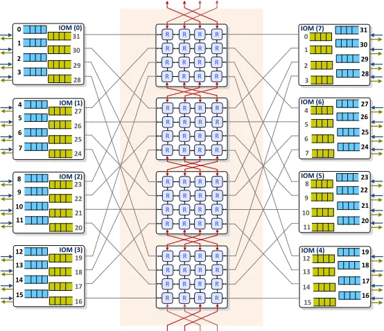
Fig. 1: An example of a (32×32) Clos-MDN switch architecture
III. HIGH-LEVELARCHITECTURE
In this section we present the switch architecture. We first outline the topology, packet buffers distribution in the switch and we provide a detailed description for the MDN modules. Second, we describe the packets dispatching process and the routing algorithm inside and in-between the MDN central modules.
A. Network topology and packet buffers
Our first contribution is to alter the middle stage of the Clos-network. Instead of common point-to-point connection crossbars, we plug Multi-Directional NoC modules and we update the packet buffers organization in the Input Modules (IMs) and Output Modules (OMs) as following: The first and second stages of the switch architecture are made of k
Input/Output Modules (IOMs), each of which is of size(n×n). Input and output ports of the Clos-MDN switch are spread on the edge modules in opposite directions as Fig.1 shows. Every IOM regroupsn input FIFOs, each of which is associated to one input port. It can receive at most one packet and sends at most one packet to a central module at every time slot. There are also n output queues per IOM each is associated to one output port and which can receive at most n packets (from the different MDN blocs) and forwards one packet to the output line card at every time slot. The middle stage is made of m MDNs, each of dimension (k×k). We remind that for an arbitrary non-blocking Clos-network, the number of outlets in any of the first-stage modules (m) can differ from the number of its inlets (n). In subsequent parts of this paper, we use the simple case Bene′snetwork for which we
set n = m. This makes the Clos-MDN switch architecture, the lowest-cost rearrangeably non-blocking Clos-network and
avoids the need for an insertion policy to distribute packets among input buffers at the traffic arrival phase1
B. The Multi-Directional NoC modules
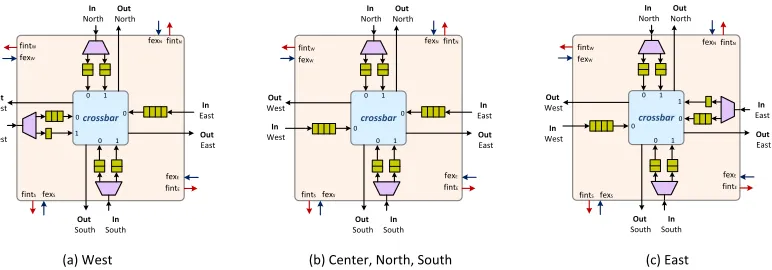
In this sub-section, we give details of the architectural design of the switch central modules. Single-stage MDN switch was introduced in [23] as an extension of the UDN proposal [13]. They both have common features but the MDN design tends to efficiently make use of the NoC concept in building a compact packet switch. An MDN is a regular 2-D mesh of size (k×k). The set of input/output pads are placed on the perimeter of the NoC as shown in Fig.3. The MDN can be thought of as the concatenation of two UDN switches where packets can flow horizontally in two opposite directions. MDN implements a buffered credit based flow control and adopts the store and forward switching mode. To avoid deadlocks, we use two Virtual Channels (VCs) to separate East/West and West/East traffic. Packets cross the first virtual channel VC0 if their corresponding output destination is located eastern to its input port. The second channel VC1 is used if the packet destination is located western to the input port. Input queued mini-routers are equipped with small crossbars and a RR arbiters to resolve input contentions. Fig.2 depicts high-level diagrams of the different mini-routers used in the MDN fabric. We opt for an asymmetrical buffer distribution among virtual channels, whereby west routers have 2/3 of the buffer depth for VC0 and 1/3 for VC1 and east routers use 1/3 of the port buffering space for VC0 and 2/3 of it for VC1.
1In the general case, a non-blocking Clos-network switch can be of any size, wherem≥2n−1. This would simply require packets insertion policy
crossbar In North Out North In West Out West In East Out East In South Out South 0 1 0 1 0 0 1 crossbar In North Out North In West Out West In East Out East In South Out South 0 1 0 1 0 0 crossbar In North Out North In West Out West In East Out East In South Out South 0 1 0 1 0 0 1 fintW fexW fintN fexN
fintSfexS fint
E fexE fintW fexW fintN fexN
fintSfexS
fintE fexE fintW fexW fintN fexN
fintSfexS
fintE fexE
[image:5.612.116.502.54.189.2](a) West (b) Center, North, South (c) East
Fig. 2: Asymmetrical buffers distribution in the different MDN mini-routers
. . . . . . . . . . . . . . . . . . NI NI NI NI NI NI NI NI NI NI NI NI
NI NI NI NI
0
1
2
k -1
0 1 2 K-1
K-1 2 1 0 K-1 2 1 0
Virtual Channel 0
Virtual Channel 1
[image:5.612.70.275.230.403.2]. . . . . . . . . . . .
Fig. 3: Central-stage MDN module
C. Packets routing in the MDNs
We consider a static packets dispatching scheme from the IOMs, for which every input FIFO constantly delivers packets to the same MDN module on the connecting link. Traffic flows do travel in all directions in the central stage modules until the external links bridging the IO modules. Based on their destination ports, packets are minimally routed inside the MDN modules. Packets are routed within a central MDN as following: The first step consists on finding out the IO module index to which is related the packets’ ultimate destination port. Upon their entry to a CM, packets are locally routed using a combination of two algorithms: “XY” algorithm and the “Modulo” routing. The “XY” algorithm has been long ago introduced for mesh NoCs. It is used to route packets in the MDN whenever the local output port is perpendicular to its input port. It simply starts by forwarding packets horizontally to the correct column (x-coordinate) and then vertically to the right row (y-coordinate). The “Modulo” algorithm is an improved version of the basic “XY”. It introduces an extra turn in one intermediate column before the last one to better balance the traffic in the mesh. It is used in the MDN switch if the local input and output ports are parallel.
Our previous results showed that a static packets dispatching
and an oblivious routing scheme, are irrelevant to skewed traffic arrivals [12]. In fact, the NoC-based switches can get congested under some traffic patterns causing the packet delays to become longer and the switch throughput to deplete. Therefore, we make the central-stage modules of the Clos-MDN switch capable of sharing traffic via intermediate links that we build according to Algorithm 1. We also use two virtual channels on each link to transport packets depending on the flow direction. This conserves the packets’ flowing direction in any CM and prevents deadlocks.
The additional connections extend the advantage of the Networks-on-Chip geometry to the Clos-network and make the multistage switch architecture a wrapped-around network. We connect theCM(r)toCM((r−1)mod m)andCM((r+
1) mod m) by means of N4 interleaved links as depicted in
Fig.1 and explained by the following logic (MRr(a, b)is the
mini-router in moduleCM(r)located in rowaand columnb
of the mesh).
Algorithm 1: Interleaved CM interconnections
1. Forr∈ {1, . . . , m−1}
2. r′←((r+ 1)mod m) and r′′←((r−1)mod m)
3. Fori∈ {1, . . . , k−1}
4. j←((k
2 +i)mod k)
5. MRr(k−1, i)connects to MRr′(0, j)
6. MRr(0, i)connects to MRr′′(k−1, j)
7. End For
8. End For
Choosing an interleaved configuration is made to ensure that sending packets from their original congested CMs to neighboring modules does not increase the remaining hops count2.
D. Inter-MDN module routing
Besides introducing the bidirectional inter-CMs links, we implement an adequate routing algorithm. Routing packets across these links is subject to some constraints. Our ultimate
goal is to maximize the switch throughput under coarse traffic without affecting the delay performance. Therefore, we adopt a metric that is suitable for the routing scheme to correlate well with the global Clos-network congestion status while being inexpensive to compute. We consider the Regional Congestion Awareness (RCA) [29] to evaluate and propagate congestion information across the central module of index r and its direct neighbors (blocs of indexes ((r −1) mod m) and
((r+1)mod m)). The congestion metric weights both distance
(hops count until the exit port) and buffers occupancy to make sure that the traffic is adaptively transferred through minimal paths and that the average packets delay is little affected by the inter-module routing decision. We define a routing quadrant to be the sub-network limited by the packet’s current position in the MDN mesh and the egress port through which it exits the current CM to the corresponding IOM. We also define the local CM information to be the information readily available at a given CM module and representing the status of all nodes (also called mini-routers) that figure in the routing quadrant. Given its current position, a packet can travel in one of four quadrants N/E3, S/E, N/W and S/W with each quadrant having exactly two possible output directions excluding the local port.
IV. PERFORMANCEANALYSIS
In this section we use simulations to evaluate the perfor-mance of the Clos-MDN switch and to compare it to state-of-the-art switching architectures. Simulation models are built on top of an event-driven simulator written in C language. We consider a wide range of workloads:
1) Bernoulli/bursty uniform 2) Bernoulli/bursty hot-spot arrivals 3) Diagonal traffic
Note that for all simulations, the capacity of the input buffers (buff) in the Clos-MDN switch is 4 packets each, unless it is otherwise stated. We perform the first set of simulations under uniform traffic. Packets are assumed to have the same fixed size and input buffers of the MDN’s mini-routers are assumed to be worth of 4 packets each. For the sake of comparison, we make the input buffers capacity of embedded mini-routers the same for the Clos-UDN and Clos-MDN switches. We also make the Clos parametersn, m
the same for both switches configurations in which case the performance disparity is mainly attribute of the NoC modules. The essence of the Clos-MDN is in the prospect of building high-capacity switching architectures with small sized NoC modules. Note that for any switch valency, a central-stage UDN4 bloc uses four times as many mini-routers as an MDN module employs. Fig.4 (a), shows that Clos-UDN has much higher packet latency than Clos-MDN switch for both Bernoullii.i.dand bursty arrivals (curves with burst sizebset to 1 and 10 respectively). The initial delay correlates with the number of NoC stages that packets need cross until exiting the central modules. After a number of time slots, the pipeline is filled in and the latency variation with the traffic load becomes
3Letters N, S, W and E correspond to North, South, West and East respectively.
4For full mesh design where the number of the unidirectional NoC stages is equal to the number of inlets/outlets [27].
quasi constant. We notice that with less on-chip mini-routers andSP = 2, the Clos-MDN outperforms a Clos-UDN switch that only relies on larger NoCs (i.e., full mesh UDNs and
SP = 1). This attests of the efficiency of the Clos-MDN design in terms of area especially that it is not expensive to run short on-chip links a bit faster.
Bursty uniform traffic can be modeled as an On/Off process with a geometric distribution and a given burst sizeb. A burst of b packets that come to the same input port of the switch during the On period are destined to the same output port. Fig.4 (a) depicts simulation results for b = 10. Both Clos-UDN/MDN switches perform under uniform bursty traffic in a similar way as they behave under Bernoulli arrivals. We notice that rising SP improves Clos-MDN performance but it still cannot achieve full throughput (82%). Overall, trading area by speedup makes the Clos-MDN switch performance by approximately23%under Bernoulli traffic and17% under bursty traffic as compared to Clos-UDN switch.
Non-uniform traffic is described by an unbalance degree
ω ∈[0,1]. We denoteρi,j, the normalized load from inputi
to output portj. It is given byω+1−ω
n·k wheni=j and 1−
ω
n·k
otherwise. The traffic is uniform whenω= 0 and directional if ω = 1 (packets are always destined to only one output port). Any intermediate value of ω implies that the traffic is a weighted mix of uniform and directional traffic also called unbalanced traffic. The next simulation set is performed to test the Clos-MDN switch tolerance to hot-spot traffic (ω = 0.5). In Fig.4 (b) we plot the average packets delay of Clos-UDN/MDN switches for different speedup factors. The switch with UDN modules performs better than the Clos-MDN if the internal NoC connections run as fast as the external line rate. However, a speedup of two suffices to noticeably reduce the packets delay and to push up the throughput of the Clos-MDN switch (from80% to99%) as clear in Fig.4 (c).
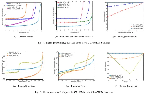
We compare the delay/throughput performance of the MDN switching architecture to a bufferless and buffered Clos-network switches; MSM (using the Concurrent RR Dispatch-ing scheme- CRRD [7]) and MMM as described in [5]. Fig.5 depicts the simulations results for the three switching architectures with the minimum optimal settings5.
Obviously, the current proposal fits in the buffered Clos architectures category. But comparing its performance to the baseline bufferless MSM helps situate the Clos-MDN and analyze its response to the traffic arrivals with respect to its features (number of packet buffers and their capacity, scheduling complexity, etc.). In Fig.5 (a) is shown the average packets latency for switches of size (256×256). The following conclusions can be drawn: A bufferless switching architecture performs well under light to medium loads however the delay rises sharply at around 40% load and never pulls down. MMM also provides low latency and outperforms MSM and Clos-MDN mainly thanks to its large capacity crosspoint buffers that help over-provision traffic instead of dropping packets or reducing the matching size (this is generally the
10 20 30 40 50 60 70 80 90 100 101
102
103
Offered Load (%)
Average Cell Delay (cell time)
Clos−UDN, SP1, b=1 Clos−MDN, SP2, b=1 Clos−UDN, SP1, b=10 Clos−MDN, SP2, b=10
(a) Uniform traffic
10 20 30 40 50 60 70 80 90 100 101
102
103
Offered Load (%)
Average Cell Delay (cell time)
Clos−MDN, SP1 Clos−MDN, SP2 Clos−UDN, SP1 Clos−UDN, SP2
(b) Bernoulli Hot-spot traffic,ω= 0.5
0 0.2 0.4 0.6 0.8 1 10
20 30 40 50 60 70 80 90 100
Unbalanced propability, (w)
Switch throughput
Clos−UDN, SP1 Clos−MDN, SP1 Clos−MDN, SP2
[image:7.612.50.554.55.388.2](c) Throughput stability
Fig. 4: Delay performance for 128-ports Clos-UDN/MDN Switches
10 20 30 40 50 60 70 80 90 100 10−1
100 101 102
103
Offered Load (%)
Average Cell Delay (cell time)
Clos−MDN, SP3 MSM−CRRD, iter2 MMM, xbuff 16
(a) Bernoulli uniform
10 20 30 40 50 60 70 80 90 100 100
101
102 103
104
Offered Load (%)
Average Cell Delay (cell time)
Clos−MDN, SP3 MSM−CRRD, iter2 MMM, xbuff 16
(b) Bursty uniform
0 0.2 0.4 0.6 0.8 1 40
50 60 70 80 90 100
Omega
Switch throughput
Clos−MDN, SP3 MSM−CRRD, iter2 MMM, xbuff 16
[image:7.612.79.545.399.538.2](c) Switch throughput
Fig. 5: Performance of 256-ports MSM, MMM and Clos-MDN Switches
10 20 30 40 50 60 70 80 90 100 101
102
103
Offered Load (%)
Average Cell Delay (cell time)
256x256, b=1 512x512, b=1 256x256, b=10 512x512, b=10
(a) Uniform traffic
10 20 30 40 50 60 70 80 90 100 101
102
Offered Load (%)
Average Cell Delay (cell time)
256x256, hot−spot traffic 512x512, hot−spot traffic 256x256, diagonal traffic 512x512, diagonal traffic
(b) Unbalanced traffic
10 20 30 40 50 60 70 80 90 100 101
102 103
104
Offered Load (%)
Average Cell Delay (cell time)
256x256, buff=4 512x512, buff=4 512x512, buff=6 512x512, buff=12
(c) Bursty non-uniform
Fig. 6: Impact of switch size on performance of Clos-MDN Switch,SP = 3
case for bufferless architectures). The Clos-MDN experiences relatively higher delay under light to medium traffic loads. The pipelined structure of the NoC-based central modules is on behalf of this initial cumulative delay. However the delay variation is quasi stable showing a good scalability of the Clos-MDN to load fluctuation.
In Fig.5 (b), we assume uniform, identical and independent reference pattern of packet bursts arrivals at the different mul-tistage switches inlets. Both MSM and MMM switches yield better latency than Clos-MDN under light loads. However MSM reiterating the CRRD matching two times experiences an abrupt delay increase (at 55% load). Besides, the
per-formance of the MMM switch degrades under bursty traffic whereas the delay variation is near constant for Clos-MDN. In Fig.5 (c) we plot the throughput variation of the different switches as we vary the unbalance degree of traffic, ω. We note that MMM experiences less performance fluctuation than MSM for which the throughput drops drastically (50%-55%
speedup of three proves enough for a (256×256) Clos-MDN switch to achieve full throughput, but it is still insufficient to ameliorate the performance of a 512-ports switch. Setting up the NoC speedup boosts the switch performance but does not resolve the persistent backlogs that can form inside the MDN modules under heavy traffic loads. In Fig.6 (b) we present the delay curves for two non-uniform traffic patterns: Hot-spot and diagonal. The latter is a very skewed traffic that is more difficult to schedule than any uniform loading. With
SP = 3, Clos-MDN still performs well under diagonal traffic and achieves full throughput under hot-spot loads.
The last set of simulations is performed under bursty hot-spot arrivals. Fig.6 (c) shows that increasing the switch valency deteriorates its response. We note that with SP = 3, the throughput of a 512-ports switch is still bounded to 76%
whenever the on-chip input buffers capacitybuff is 4 packets. Actually, skewed and heavy loads of packets arriving in bursts to the switch inlets produce backlogs and translate into throughput deterioration. Other than speeding up the NoC fabric, extending the input buffering space of all mini-routers to 6 packets each drastically enhances the throughput performance. However our simulations show that there is little interest in further increasing the buffers capacity (the switch throughput converges with buff= 6 and there is little delay improvement if we rise buff to 12packets).
V. CONCLUSION
In this paper, we made a radical change at the heart of a three-stage Clos-network switch. We use Multi-Directional Networks-on-Chip modules (MDNs) to overcome some short-comings of conventional crossbar-based multistage switches. Adopting MDNs obviates the need for complex and costly buffering structures at the input modules of the switch. It also avoids complex and synchronized scheduling processes that bufferless Clos switches need and large crosspoint buffers which common MMM switches require. Compared to the Clos-UDN switch, the current proposal scales better in size load fluctuation. Thanks to the efficiently designed MDN modules, the switch offers a range of settings that can be tunned to sleekly achieve given performance involving the minimum possible cost and complexity.
VI. ACKNOWLEDGMENT
This work was supported by the EU Marie Curie Grant (SCALE: PCIG-GA-2012-322250)
REFERENCES
[1] “Cisco,” 2016. [Online]. Available: http://www.cisco.com/c/en/us/ products/switches/nexus-5000-series-switches/datasheet-listing.html [2] “Juniper Networks,” June 2015. [Online]. Available: http://www.juniper.
net/assets/us/en/local/pdf/datasheets/1000414-en.pdf
[3] Z. Dong, R. Rojas-Cessa, and E. Oki, “Memory-Memory-Memory Clos-network Packet Switches with In-Sequence Service,” inHPSR, 2011 International Conference on. IEEE, 2011, pp. 121–125.
[4] H. J. Chao, J. Park, S. Artan, S. Jiang, and G. Zhang, “TrueWay: a Highly Scalable Multi-Plane Multi-Stage Buffered Packet Switch,” in
HPSR, 2005 International Conference on. IEEE, 2005, pp. 246–253. [5] Z. Dong and R. Rojas-Cessa, “Non-blocking Memory-Memory-Memory
Clos-network Packet Switch,” inSarnoff Symposium, 2011 34th IEEE. IEEE, 2011, pp. 1–5.
[6] Y. Xia, M. Hamdi, and H. J. Chao, “A Practical Large-capacity Three-stage Buffered Clos-network Switch Architecture,”IEEE Trans. Parallel Distrib. Syst., vol. 27, no. 2, pp. 317–328, 2016.
[7] E. Oki, Z. Jing, R. Rojas-Cessa, and H. J. Chao, “Concurrent Rround-Robin-based Dispatching Schemes for Clos-network Switches,”
IEEE/ACM Trans. Netw, vol. 10, no. 6, pp. 830–844, 2002.
[8] F. M. Chiussi, J. G. Kneuer, and V. P. Kumar, “Low-cost Scalable Switching Solutions for Broadband Networking: the ATLANTA archi-tecture and Chipset,”IEEE Commun. Mag., vol. 35, no. 12, pp. 44–53, 1997.
[9] X. Li, Z. Zhou, and M. Hamdi, “Space-Memory-Memory Architecture for Clos-network Packet Switches,” inICC, 2005 International Confer-ence on. IEEE, 2005, pp. 1031–1035.
[10] K. Pun and M. Hamdi, “DISTRO: A Distributed Static Round-Robin Scheduling Algorithm for Bufferless Clos-network Switches,” in
GLOBECOM., vol. 3. IEEE, 2002, pp. 2298–2302.
[11] Y. Xia and H. J. Chao, “Module-Level Matching Algorithms for MSM Clos-network Switches,” inHPSR, 2012 International Conference on. IEEE, 2012, pp. 36–43.
[12] F. Hassen and L. Mhamdi, “Congestion-Aware Multistage Packet-Switch Architecture for Data Center Networks,” to appear in GLOBECOM. IEEE, 2016.
[13] L. Mhamdi, K. Goossens, and I. V. Senin, “Buffered Crossbar Fabrics Based on Networks on Chip,” inCNSR, 2010 Eighth Annual. IEEE, 2010, pp. 74–79.
[14] J. Perry, A. Ousterhout, H. Balakrishnan, D. Shah, and H. Fugal, “FASTPASS: A Centralized Zero-Queue Datacenter Network,” inACM SIGCOMM Computer Communication Review, vol. 44, no. 4. ACM, 2014, pp. 307–318.
[15] M. Alizadeh, T. Edsall, S. Dharmapurikar, R. Vaidyanathan, K. Chu, A. Fingerhut, F. Matus, R. Pan, N. Yadav, G. Vargheseet al., “CONGA: Distributed Congestion-Aware Load Balancing for Datacenters,” inACM SIGCOMM Computer Communication Review, vol. 44, no. 4. ACM, 2014, pp. 503–514.
[16] P. Wang and H. Xu, “EXPEDITUS: Distributed Load Balancing with Global Congestion Information in Data Center Networks,” in Proceed-ings of the 2014 CoNEXT on Student Workshop. ACM, 2014, pp. 1–3. [17] K. He, E. Rozner, K. Agarwal, W. Felter, J. Carter, and A. Akella, “PRESTO: Edge-based Load Balancing for Fast Datacenter Networks,”
ACM SIGCOMM Computer Communication Review, vol. 45, no. 4, pp. 465–478, 2015.
[18] S. Ghorbani, B. Godfrey, Y. Ganjali, and A. Firoozshahian, “Micro Load Balancing in Data Centers with DRILL,” in Proceedings of the 14th ACM Workshop on Hot Topics in Networks. ACM, 2015, p. 17. [19] H. J. Chao, Z. Jing, and S. Y. Liew, “Matching Algorithms for
Three-Stage Bufferless Clos Network Switches,”IEEE Commun. Mag., vol. 41, no. 10, pp. 46–54, 2003.
[20] J. Kleban and A. Wieczorek, “CRRD-OG: A Packet Dispatching Algorithm with Open Grants for Three-Stage Buffered Clos-network Switches,” in2006 Workshop on HPSR. IEEE, 2006, pp. 6–pp. [21] F. Moraes, N. Calazans, A. Mello, L. M¨oller, and L. Ost, “HERMES:
An Infrastructure for Low Area Overhead Packet-Switching Networks on Chip,”INTEGRATION, the VLSI journal, vol. 38, no. 1, pp. 69–93, 2004.
[22] E. Bastos, E. Carara, D. Pigatto, N. Calazans, and F. Moraes, “MOTIM-A Scalable “MOTIM-Architecture for Ethernet Switches,” inISVLSI’07. IEEE, 2007, pp. 451–452.
[23] K. Goossens, L. Mhamdi, and I. V. Senin, “Internet-router Buffered Crossbars based on Networks on Chip,” in DSD’09. 12th Euromicro Conference on. IEEE, 2009, pp. 365–374.
[24] T. Karadeniz, L. Mhamdi, K. Goossens, and J. Garcia-Luna-Aceves, “Hardware Design and Implementation of a Network-on-Chip Based Load Balancing Switch Fabric,” inReConFig. IEEE, 2012, pp. 1–7. [25] A. Bitar, J. Cassidy, N. Enright Jerger, and V. Betz, “Efficient and
programmable ethernet switching with a NoC-enhanced FPGA,” in
Proceedings of the tenth ACM/IEEE symposium on Architectures for Networking and Communications Systems. ACM, 2014, pp. 89–100. [26] T. Karadeniz, A. Dabirmoghaddam, Y. Goren, and J.
Garcia-Luna-Aceves, “A New Approach to Switch Fabrics based on Mini-Router Grids and Output Queueing,” in ICNC, conference on. IEEE, 2015, pp. 308–314.
[27] F. Hassen and L. Mhamdi, “A Multi-Stage Packet-Switch Based on NoC Fabrics for Data Center Networks,” in2015 IEEE Globecom Workshops (GC Wkshps). IEEE, 2015, pp. 1–6.
[28] ——, “A Scalable Packet-Switch based on Output-Queued NoCs for Data Centre Networks,” in ICC, 2016 International Conference on. IEEE, 2016, pp. 1–6.