A self-powered triboelectric velocity sensor for
impact detection in composite structures
Cristobal Garcia 1,2,3 *, and Irina Trendafilova 1
1University of Strathclyde, Department of Mechanical and Aerospace Engineering, 75 Montrose Street, G1 1XJ, Glasgow, UK.
2IMDEA: Madrid Institute for advanced studies of materials, C/ Eric Kandel 2, 28906, Getafe, Madrid, Spain.
3FIDAMC: Foundation for the Research, Development and Application of Composite Materials, Avda. Rita Levi Montalcini 29, 28906, Getafe, Madrid, Spain.
Abstract. Impacts and collisions are frequent in aircrafts, wind turbines, bridges and other composites structures. Some examples are the collisions between birds and aircrafts during take-off and landing or the damages caused in wind turbines due to the impact of hailstones. Hence, the detection and measurement of these impacts is the vital importance for monitoring the health state of composites structures as aircrafts or wind turbines. The main purpose of the paper is to demonstrate the sensitivity of a novel triboelectric sensor for impact detection in composite structures as aircrafts. For this study, composite plates adhered with the fabricated triboelectric sensor are subjected to various impact velocities using a drop-weight machine. The sensor electrical responses due to the impacts are measured with the aim to evaluate the sensitivity of the developed triboelectric sensor to variations in the impact velocities. The results show that the sensor electric responses increase linearly with impact velocity in the range between 1.3 and 2.4 m/s. This paper is the first attempt to demonstrate the potential applications of triboelectric sensors to measure the velocity of the impacts in composite structures, which play an important role for structural health monitoring in aircrafts, bridges and other composite structures.
1 Introduction
Impacts and collisions are frequent in airplanes, wind turbines, bridges and other composite structures. For example, the operational state of wind turbines can be seriously affected due to the impact of hailstones. The integrity of aircraft composite structures can be seriously damaged because of the impact of birds. Therefore, impacts are responsible for an important number of accidents in aerospace and civil structures affecting the working and health state of aircrafts, bridges and other structures made of composite laminates. Consequently, the detection and measurement of the impacts is the vital importance for monitoring the health of composite structures.
Impact sensors are usually classified according their operating principle as piezoelectric [1], resistive [2], triboelectric [3] capacitive [4] and optical types [5]. Among them, the sensors operating based on the triboelectric effect are attracting much attention in the last years. The main benefit of triboelectric sensors is that they are self-powered and do not require an external power supply or battery to power the sensor. Furthermore, they can be easily fabricated in the large scale using cheap materials and lower cost technology as compared to other sensor types.
The aim of this paper is to demonstrate the sensitivity of a novel triboelectric sensor for detection of impacts in composite structures as aircrafts. For this study, composite laminate plates adhered with a triboelectric sensor are impacted using a drop-weight machine equipped with an optical sensor to measure the velocity of the impacts. The electric sensor responses are acquired in form of voltage and current with the purpose to assess the sensitivity of the developed triboelectric sensor for impact velocity detection. The main contribution of the experiment is to demonstrate that the fabricated triboelectric sensor can detect and measure the velocity of the impacts applied in the composite plates.
This study includes some important findings which make an important contribution to science. Firstly, numerous works has been published to demonstrate the important applications of triboelectric sensors as self-powered active sensors for touches [3], pressures [6], vibrations and other mechanical motions [7]. However, only a very few publications [8] analysed the potential of triboelectric sensors for measuring the impact velocities. Thus, it can be said that the results included in this work are novel and the utmost importance for impact monitoring. Secondly, this investigation represents the first attempt to demonstrate successfully that triboelectric sensors can be used to detect and measure the velocity of the impacts in composite structures.
The working principle of the developed triboelectric sensor based on the triboelectric effect caused by the friction between polyvinyl fluoride nanofibers and polypropylene. A detailed description of the working mechanism of the sensor is included in section 4.1. In the triboelectric sensor, polyvinyl fluoride nanofibers are used as negative triboelectric material because of their strong tendency to gain triboelectric charges from other triboelectric materials [9]. Additionally, the large surface area of the nanofibers increases the generation of triboelectric charges which results in a larger triboelectric effect. In contrast, a film of Polypropylene is used as positive triboelectric mat due to their strong tendency to loose triboelectric charges from other materials as indicated in the triboelectric series [9].
The rest of the paper is organised as follows: Section 2 describes the fabrication and structural design of the novel triboelectric sensor. Section 3 explains the experimental test carried out to detect and measure the velocity of the impacts applied in composite plates. The results obtained in the experiment are presented and discussed in the section 4. The last section offers some conclusions.
2 Design of the triboelectric sensor
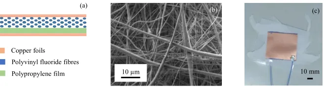
A schematic description of the structure used in the developed sensor is schematically shown in Fig. 1(a). The top part of the triboelectric sensor is made of polyvinyl fluoride nanofibers spun on copper foil and the bottom part of the sensor is formed by polypropylene adhered to copper foil. The role of the copper foils is to act as electrodes for
the sensor while polyvinyl fluoride nanofibers and the polypropylene film are the sensing triboelectric materials.
[image:3.482.74.404.187.276.2]Fig. 1(b) illustrates a scanning electron microscope image of the polyvinyl fluoride nanofibers. The image shows good quality nanofibers with an average size of 800 ± 350 nm and random orientation. The nanofibers are prepared using the technique of electrospinning and the operational parameters indicated in [8]. Fig. 1(c) displays a digital photography of the assembled triboelectric sensor with a small size of 55 x 55 mm.
Fig. 1. Design of the triboelectric sensor: (a) Schematic description of the structure used in the sensor. (b) Scanning electron microscope image of polyvinyl fluoride nanofibers and (c) digital photography of the assembled sensor.
3 Application of the sensor for impact velocity measurement in
composite plates
[image:3.482.70.412.452.528.2]The aim of the section is to describe the experiment used to assess the sensitivity of the novel triboelectric sensor to measure the velocities of the impacts applied in the composite plates. This is important to demonstrate the potential applications of the triboelectric sensor for structural health monitoring in composite structures as airplanes, wind turbines and bridges.
Fig. 2. Experiment to assess the sensitivity of the sensor for impact velocity measurement: (a) The triboelectric sensor is adhered to the static clamp of the impact machine. (b) A composite laminate plate is mounted on the sensor and (c) the impact test is conducted on a composite plate fixed with simple support boundary conditions around the four edges and the sensor response is measured.
Fig. 2 shows a schematic description of the experiment carried out to assess the sensor sensitivity to various velocity impacts in composite plates. At first, the triboelectric sensor is adhered to the static clamp of the impact machine (CEAST 9350) as shown in Fig. 2(a). Subsequently, a carbon laminate plate with a length of 120 mm and a thickness of 70 mm is mounted on the triboelectric sensor as illustrated in Fig. 2(b). At last, the composite plate is impacted at controlled impact velocity and the sensor electric response is measured in form
(b) (c)
(a)
(b)
Copper foils
Polyvinyl fluoride fibres Polypropylene film
(a)
10 µm 10 mm
of voltage and current using a commercial oscilloscope and a digit multimeter respectively. During the experiment, composite plates are impacted using six different impact velocities from 1.3 to 2.4 m/s.
4 Results and discussion
4.1 Operating principle of the sensor
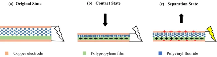
As stated above, the triboelectric sensor is constituted by a polypropylene film on one side, and by a layer of polyvinyl fluoride nanofibers on the other side. The electric response of the sensor is due to the triboelectric effect caused by the friction between the film of polypropylene and the nanofibers of polyvinyl fluoride.
[image:4.482.66.418.387.480.2]Fig. 3 shows a schematic description of the operating principle of the triboelectric sensor. In the initial state, there is no friction between the polypropylene and the polyvinyl fluoride nanofibers. As a result, there is no generation of triboelectric charges what results in no electric output as illustrated in Fig. 3(a). When a composite plate is impacted, the configuration of the sensor changes from the initial state to the contact state as represented in Fig. 3(b). In this state, the friction between the triboelectric materials generates charges with negative signs in polyvinyl fluoride nanofibers and positive signs in polypropylene. When the impact applied in the composite plate is released, the sensor configuration varies from the contact state to the separation state shown in Fig. 3(c). Thus, the triboelectric charges separated which results in a potential difference and an instantaneous electric signal. At last, the triboelectric charges disappear and the sensor revert backs to the initial state.
Fig. 3. Operating principle of the triboelectric sensor: (a) Original position of the sensor before the impact. (b) Contact state of the sensor during the impact and (c) separation state after the impact.
4.2 Effect of impact velocity on voltage output
A drop weight machine was used to impact the composite plates at controlled velocities and the responses of the sensor were measured using a commercial oscilloscope as explained in section 3. The idea is to evaluate the sensitivity of the developed sensor to detect and measure the velocity of the impacts.
Fig. 4 (a) shows the voltage responses of the triboelectric sensor when the composite plates are impacted at six different velocities. It can be clearly observed that the amplitude of the electric responses is affected by the impact velocity and the voltage output increases from 1.36 to 2.40 V as the impact velocity increases from 1.3 to 2.4 m/s. This behaviour can be explained because the friction between the polyvinyl fluoride nanofibers and the
Copper electrode
(a) Original State (b) Contact State (c) Separation State
Polyvinyl fluoride Polypropylene film
+ + + + + + + + + +
- - - + + + + + + + + + + - - - - + + + + +
of voltage and current using a commercial oscilloscope and a digit multimeter respectively. During the experiment, composite plates are impacted using six different impact velocities from 1.3 to 2.4 m/s.
4 Results and discussion
4.1 Operating principle of the sensor
[image:5.482.76.388.110.237.2]As stated above, the triboelectric sensor is constituted by a polypropylene film on one side, and by a layer of polyvinyl fluoride nanofibers on the other side. The electric response of the sensor is due to the triboelectric effect caused by the friction between the film of polypropylene and the nanofibers of polyvinyl fluoride.
Fig. 3 shows a schematic description of the operating principle of the triboelectric sensor. In the initial state, there is no friction between the polypropylene and the polyvinyl fluoride nanofibers. As a result, there is no generation of triboelectric charges what results in no electric output as illustrated in Fig. 3(a). When a composite plate is impacted, the configuration of the sensor changes from the initial state to the contact state as represented in Fig. 3(b). In this state, the friction between the triboelectric materials generates charges with negative signs in polyvinyl fluoride nanofibers and positive signs in polypropylene. When the impact applied in the composite plate is released, the sensor configuration varies from the contact state to the separation state shown in Fig. 3(c). Thus, the triboelectric charges separated which results in a potential difference and an instantaneous electric signal. At last, the triboelectric charges disappear and the sensor revert backs to the initial state.
Fig. 3. Operating principle of the triboelectric sensor: (a) Original position of the sensor before the impact. (b) Contact state of the sensor during the impact and (c) separation state after the impact.
4.2 Effect of impact velocity on voltage output
A drop weight machine was used to impact the composite plates at controlled velocities and the responses of the sensor were measured using a commercial oscilloscope as explained in section 3. The idea is to evaluate the sensitivity of the developed sensor to detect and measure the velocity of the impacts.
Fig. 4 (a) shows the voltage responses of the triboelectric sensor when the composite plates are impacted at six different velocities. It can be clearly observed that the amplitude of the electric responses is affected by the impact velocity and the voltage output increases from 1.36 to 2.40 V as the impact velocity increases from 1.3 to 2.4 m/s. This behaviour can be explained because the friction between the polyvinyl fluoride nanofibers and the
Copper electrode
(a) Original State (b) Contact State (c) Separation State
Polyvinyl fluoride Polypropylene film
+ + + + + + + + + +
- - - + + + + + + + + + + - - - - + + + + +
- - - - -
polypropylene film increase when the composite plates are subjected to higher impact velocities.
[image:5.482.73.396.483.616.2]
Fig. 4. Performance of the triboelectric sensor: (a) Voltage output when the composite plates are impacted at six different velocities and (b) voltage amplitude as a function of the impact velocity.
Fig. 4 (b) shows the voltage amplitudes as a function of the impact velocity. It is noticed that the voltage amplitudes and the impact velocity exhibit a linear relationship with a coefficient of determination R2=0.978. This is important as linear relationships are always
preferred for practical applications of the sensor. It can be concluded that the amplitude of the voltage output depends on the impact velocity, and the voltage responses increase proportionally with the impact velocity. These results demonstrate that the triboelectric sensor can be used to detect and measure the velocity of the impacts applied in the composite plates.
4.3 Effect of impact velocity on current output
A drop weight machine was used to subject the composite plates at controlled impact velocities and the sensor impact responses were acquired using a digital multimeter as indicated in section 3. The purpose of the experiment is to assess the sensitivity of the triboelectric sensor to quantify the velocity of the impacts.
Fig. 5. Performance of the triboelectric sensor: (a) Current output when the composite plates are impacted at six different velocities and (b) maximum current as a function of the impact velocity.
(a) (b)
2.44 m/s 2.26 m/s 2.05 m/s 1.83 m/s 1.58 m/s 1.27 m/s
1.0 1.5 2.0 2.5 1.0 1.5 2.0 2.5 Voltage (V) Velocity (m/s) -2 -1 0 1 2 Voltage (V) Time (b) (a) 2.44 m/s 2.26 m/s 2.05 m/s 1.83 m/s 1.58 m/s 1.27 m/s 0 150 300 450 Current (nA)
Time 1.0 1.5 2.0 2.5
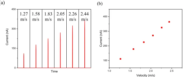
Fig. 5 (a) displays the current responses of the triboelectric sensor when the composite plates are impacted at six different velocities. The results show the sensor electric responses are affected by the impact velocity and the current output goes up from 111 to 364 nA as the impact velocity changes from 1.3 to 2.4 m/s. As stated above, the increase in the electric responses is caused by the friction between the triboelectric materials.
Fig. 5 (b) shows the maximum current as a function of the impact velocity. It can be clearly seen that the current responses and the impact velocity exhibit a linear relationship with a very good linear approximation of R2=0.998. The linear behaviour can be attributed
due to the proportional increase of the triboelectric charges. In general, it can be said that the current output is affected by the impact velocity, and current responses increase linearly with the impact velocity. This experiment demonstrates that the novel triboelectric sensor detects and measure the velocity of the impacts applied in the composite plates.
5 Conclusions
Impacts and collisions are frequent in aircrafts, wind turbines, bridges and other structures made of composite materials. The main achievement of this work is to demonstrate that a novel triboelectric sensor can be used to detect and measure the velocity of the impacts applied in composite plates. The results show that the amplitude of the sensor electric responses is affected by the impact velocity. The voltage and current responses show a good linear approximation with the impact velocity in the range from 1.3 to 2.4 m/s. This paper expands and demonstrates the potential of triboelectric sensors to detect and evaluate the impacts in composite structures, which play an important role for structural health monitoring in aircrafts, bridges and other composite structures.
The authors wish to specially thank Dr. Roberto Guzman de Villoria for supporting the collaboration between the University of Strathclyde and the advanced research centres IMDEA Materials Institute and FIDAMC. We are also very grateful to Jose Luis Jimenez for their technical support with the drop-weight impact tests and the preparation of the composite specimens.
References
[1] S. Joshi, G.M. Hedge, M.M. Nayak, K. Rajanna, Sens. Actuator A-Phys., 199, 272-282 (2013)
[2] H. Zhang, E. So, IEEE Trans. Syst. Man Cybern. Part B, 32, 57-65 (2002)
[3] G. Zhu, W.Q. Yang, T. Zhang, Q. Jing, J. Chen, Y.S. Zhou, P. Bai, Z.L. Wang, Nano Lett., 14, 3208-3213 (2014)
[4] C. Metzger et al., Appl. Phys. Lett., 92, 013506 (2008)
[5] J.S. Heo, J.H. Chung, J.J. Lee, Sens. Actuators A, 126, 312-327 (2006)
[6] K.Y. Lee, H.J. Yoon, T. Jiang, X. Wen, W. Seung, S.W. Kim, Z.L. Wang, Adv. Energy Mater., 6, 1502566 (2016)
[7] S. Wang, L. Lin, Z.L. Wang, Nano Energy, 11, 436-452 (2015)
[8] C. Garcia, I. Trendafilova, R. Guzman de Villoria, J. Sanchez del Rio, MATEC Web. Conf., 148, 14005 (2018)
[9] C. Garcia, I. Trendafilova, R. Guzman de Villoria, J. Sanchez del Rio, Nano Energy,
50, 401-409 (2018)