An Iterative Detection Aided Unequal Error
Protection Wavelet Video Scheme Using Irregular
Convolutional Codes
A. Q. Pham, J. Wang, L. L. Yang, and L. Hanzo
School of ECS, University of Southampton, SO17 1BJ, UK Tel: +44-23-8059 3125, Fax: +44-23-8059 4508
Email:{apq03r,jw02r,lly,lh}@ecs.soton.ac.uk, http://www-mobile.ecs.soton.ac.uk
Abstract— A wavelet-based videophone scheme proposed, where the video bits are Unequal Error Protection (UEP) using Irregular Convolutional Codes (IRCCs). The proposed system uses Adaptive Arithmetic Coding (AAC) for encoding the motion vectors and individual wavelet subband coefficients. The turbo-equalized IRCC-aided videophone scheme is capable of attaining a near unimpaired video quality for channel Signal-to-Noise Ratios (SNRs) in excess of about 4.5dB over a five-path dispersive AWGN channel.
I. MOTIVATION
Under a number of idealistic conditions Shannon’s source and channel coding separation theorem [1] has shown that source and channel coding may be carried out separately. This has resulted in primarily independent development of source and channel codecs in the design of communication systems. However, in practice, the joint design of source and channel codecs constitutes a promising design in the context of practical finite-complexity, finite-delay speed [6] and video [5] systems. A well-proven approach to joint source-channel coder design is to cascade a source coder and a channel coder, and appropriately split the total overall bitrate between the source encoder and channel encoder. Typically Unequal Error Protection(UEP) is used for protecting the more vulnerable source bits.
In our system study, we invoke the wavelet video codec, proposed by the BBC Research and Development Department, as our source coder [15]. This source codec is capable of efficiently compressing video and yet achieving a high re-constructed video quality at a low bit-rate. As most video codecs, the wavelet codec invokes motion compensation for the successive video frames and Adaptive Arithmetic Coding (AAC) [8] of the motion vectors as well as of subbands’ data for the sake of achieving a high compression efficiency. However, the employment of AAC renders the compressed
[image:1.595.370.502.235.367.2]The financial support of the government of Vietnam, of the EPSRC, Swindon UK and that of the EU under the auspices of the PHOENIX as well as NEWCOM projects is gratefully acknowledged.
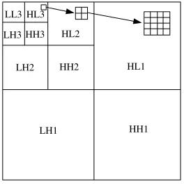
Fig. 1. The 3-level Wavelet Decomposition.
video bitstream sensitive to channel errors since the predictive coding inflicts error propagation upon the future frames as a share-ware design alternative to the Motion Picture’s Expert Group’s MPEG4 codec [9], which uses quite different design principles.
The allocation of UEP-based channel coding to the video bits is typically based on the codec’s bit-sensitivity analysis [5][6]. The family of Irregular Convolutional Codes (IRCCs) proposed by Tuchler and Hagenauer [11] has an innate ability to support UEP. This UEP property will be exploited in our proposed system for protecting the wavelet-compressed video stream, and powerful iterative detection will be used [7].
II. SOURCECODING
A. Note
The basic philosophy of two-dimensional subband or wavelet-based video coding is that the video frame or the Motion Compensated Error Residual (MCER) frame is de-composed into a number of subbands containing the different-frequency representations of the original video or MCER frame. The decomposition to subbands is typically carried out in a number of consecutive steps, as outlined for example for a 10-subband video codec on page 629 of [5]. Briefly,
DW
iQ
iDWT
FB MC
Entropy
iQ
iDWT
FB
ME
x"(n) MV
x’(n−1) MV
x(n) x’(n−1)
x(n)
x"(n)
x’(n−1) x’(n) r’(n) r’(n)
Decoded Video Sequence
x(n) : Current frame r(n) : Residue, x(n) −x"(n) MC : Motion Compensation FB : Frame Buffer x"{n} : Prediction for x(n) r’(n) : Decoded residue
ME : Motion Estimation IDWT: Inverse DWT x’(n) : Reconstructed Frame DWT : Discrete Wavelet Transform Q : Quantizer
IQ : Inverse Quantizer
Entropy Encoder
w(n) z(n)
w’(n) w(n)
z(n)
Q Decoder
MC x’(n)
[image:2.595.51.293.41.198.2]r(n)
Fig. 2. Block diagram of the Wavelet Video Encoder.
the first decomposition step seen in Fig 1 splits the frame into four ’quadrants’, representing the High (H) and Low (L) frequency horizontal as well as vertical direction details in the frame. Hence the quadrant HH1 contains the high-frequency horizontal and vertical information found in the original full-band frame. By contrast, HL1 and LH1 indicate the represen-tation of the frame, where the high horizontal but low vertical and the low horizontal but high vertical frequency components have been retained. All these frame-quadrants appear to have quarter of the original frame’s size, since before the subband halving operation the video signal was decimated by a factor of two. As seen in Fig 1, the subjectively most important LL1 video segment is split further in two consecutive band-halving steps. This tree-structure based frequency band splitting allows the designer to selectively allocate the source encoding bits to those particular frequency bands, where they have the most beneficial subjective video quality improvements. The video codec used Daubechies’ so-called 9/7 biorthogonal filters in [4], where 9 and 7 denote the number of coefficients in high-pass and low-high-pass filters.
As in most existing video compression standards, each video frame is encoded in either intra-frame mode, where the original video frame is directly encoded, or in inter-frame mode, where the MCER generated with reference to the previous decoded frame is encoded. Fig 2 portrays the simplified block diagram of the wavelet video decoder.
In the intra-frame mode, the video frame is Discrete Wavelet Transformed (DWT) [16] and then quantised in the blockQof Fig 2, in order to produce a set of quantised DWT coefficients Z(n)for all the 10 subbands. After quantization, the lowest-frequency DWT coefficients, namely the Direct Current (DC) coefficients are separated from the remaining coefficients, which are also often referred to as the Alternating Current (AC) coefficients. The DC coefficients are encoded by using a differential DC component encoding method, employing the DC values of the previous video frame as
reference. Both the differentially encoded DC coefficients and the AC DWT coefficients are entropy coded with the aid of ACC [8].
In the inter-frame mode, the original video frame is divided into 12x12-pixel overlapped blocks. Sixteen adjacent 12x12-pixel luminance blocks and sixteen 6x6-pixel color difference blocks are then combined to form a so-called MacroBlock (MB), which has 52x44 luminance pixels and 26x22x2 chrominance pixels. In this mode, a predicted MBP is formed with the aid of motion-compensation using one or more reference frame(s) on a MB basis. The Motion Vectors (MVs) are quantized, AAC encoded and transmitted to the receiver. The predicted MBP is then subtracted on a pixel-by-pixel basis from its motion-shifted best-matching counterpart in the reference frame for the sake of producing the MCER. Finally, the MCER is encoded [5].
B. Video bit allocation
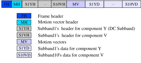
The bitstream of all video frames begins with a video frame header, as seen in Fig 3. The header is followed by the MV header, by the 30 subband DWT headers, MVs, and 30 subband DWT coefficients, as seen in Fig 3 (10 subbands for each of the Y, U, V components). The frame header
Fig. 3. The structure of the encoded video frame.
commences with thecurrent frame’s index(32 bits), followed by a number of other control parameters concerningwhether
or not a frame has to be skipped, the encoding mode(Intra, or Inter-frame), the number of reference frames used in MC, and the reference frame indices, etc. This is the most error-sensitive segment of the encoded video, since the entire video frame will be dropped, if the header is received in error.
The MV header and subband header information have the next level of importance, since motion compensation and/or wavelet decomposition cannot be performed without it. The MV data and the DWT coefficients transmitted at the end of the frame are the least error sensitive . The error sensitivity of these bits will be discussed in Section III.
III. BITSENSITIVITYSTUDY
[image:2.595.322.549.351.453.2]its bits in the encoded video frame and then evaluating the average PSNR degradation inflicted. The simulations were carried out using a 150-frame duration, 144x176-pixel QCIF-resolution Miss America video clip. The PSNR degradations were recorded for each of the parameters under the following conditions:
1) The effects of corruption on the wavelet video header parameters were somewhat difficult to estimate, because these parameters contain vital information related to the entire video sequence, and to a particular video frame. The decoder cannot even commence its decoding operations, when those parameters are corrupted. 2) When for example the sensitivity of bit 1 of an
intra-frame coded picture was investigated, this bit was con-sistently corrupted in each occurrence of an intra-frame coded picture, while keeping all other bits of the same frame intact.
More details on the bit allocation used within a frame are provided in Table I, where Y,U,V represent the luminance and two colour difference components of the video frame. An
The number of subband bits
Y comp U comp V comp
DC subband 1888 116 502
Subband 9 466 28 109
Subband 8 1049 145 230
Subband 7 1208 110 273
Subband 6 490 0 65
Subband 5 1038 60 104
Subband 4 1504 0 334
Subband 3 0 0 0
Subband 2 215 0 0
Subband 1 302 0 0
TABLE I
THE NUMBER OF SUBBAND BITS IN THE FIRST FRAME OF THEMISS
AMERICAQCIFVIDEO SEQUENCE USING INTRA-FRAME MODE.
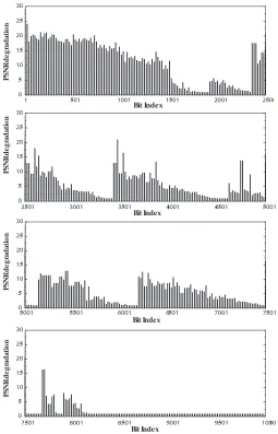
overview of the objective Peak Signal to Noise Ratio (PSNR) degradations inflicted by the systematic bit corruption events upon the MVs and subband DWT coefficients is given in Fig 4. Observe in this figure that
1) The bit sensitivity is typically higher at the beginning of a subband and then reduces towards the end of the subband, which is because an error at the beginning of a AAC segment corrupts more bits than one near the end of it.
2) The subband’s bit sensitivity also depends on the partic-ular subband’s frequency. More specifically at the same position of a low frequency subband, the bit sensitivity is higher and vice versa.
3) The number of subband DWT coefficients is an other factor influencing the sensitivity of a subband, since
1 501 1001 1501 2001 2501
0 5 10 15 20 25 30
2501 3001 3501 4001 4501 5001
0 5 10 15 20 25 30
5001 5501 6001 6501 7001 7501
0 5 10 15 20 25 30
7501 8001 8501 9001 9501 10001
0 5 10 15 20 25 30
Bit Index
Bit Index
Bit Index
Bit Index
P
S
N
R
de
g
ra
d
a
ti
o
n
P
S
N
R
de
g
ra
d
a
ti
o
n
P
S
N
R
de
g
ra
d
a
ti
o
n
PS
N
R
d
e
g
ra
d
a
ti
o
n
Fig. 4. Average PSNR degradation due to the corruption of the Y component for the Miss America QCIF video sequence encoded at 30 frame/s using intra-frame mode.
the so-callled context-based AAC continuously updates based on the past received symbols for the sake of decoding the remaining part of the subband concerned consequently the rest of the entire subband data is affected. The same characteristic behaviour can also be observed for the MVs.
[image:3.595.310.565.38.435.2]5 10 15 20 25 30 35 40 0
5 10 15 20 25 30 35 40
PSNR degradation
Frame Index
[image:4.595.57.294.32.188.2]PSNR degradation (dB)
Fig. 5. PSNR degradation due to the corruption of the first bit of the DC subband in intra-frame mode and its propagation to the subsequent frames for the Miss America QCIF video sequence encoded at 30 frame/s.
5 10 15 20 25 30 35 40
Frame Index
0 5 10 15 20 25 30 35 40
P
SN
R
degr
ad
at
io
n
(
dB
)
PSNR degradation
Fig. 6. PSNR degradation due to the corruption of the first bit of the motion vectors in the first forward predicted frame and its propagation to the subsequent frames for the Miss America QCIF video sequence encoded at 30 frame/s.
IV. SYSTEMMODEL
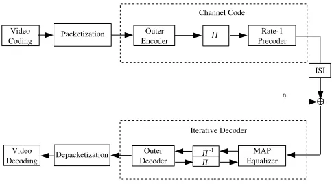
The performance of the wavelet codec was investigated, when communicating over dispersive AWGN channels. In order to reduce the channel induced Inter-Symbol Interference (ISI), powerful turbo equalization schemes were employed. The system model is depicted in Fig. 7. At the transmitter, the input video data is first compressed by the wavelet encoder and then packetized into fixed-length packets before being fed into the channel encoder. The channel encoder consists of an outer encoder and a rate-1 precoder [18], which are separated by the interleaver Π of Fig 7. The outer code adds redundancy for the sake of providing protection for the video data, while the precoder renders the channel recursive so that reduced bit error rates [18]. On the other hand, at the receiver a turbo equalizer is invoked, which consists of an inner channel equalizer and an outer channel decoder. Both of them are capable of processing soft inputs and generating soft outputs, which are exchanged between the two components in a number of consecutive iterations for the sake of improving
[image:4.595.316.558.110.247.2]the attainable decoding/detection performance. At the last iteration hard decisions are made, and the resultant bit stream is depacketized and fed into the wavelet decoder for the sake of reconstructing the video sequence.
Fig. 7. System Model
To be specific, the proposed scheme employs an IRCC scheme as the outer channel code, which was designed to match the channel characteristics as well as to provide UEP for the video data. An IRCC is constructed from a set of subcodes [10], which have different coding rates and are generated using puncturing from the same mother convolutional code. Each subcode encodes a fraction of the input video bits while maintaining the overall coding rate at a specified value. For more details on the design of IRCCs, please refer to [13], [10], where the same IRCC was used, except that the coding rate ratios of the subcodes were different. The design method proposed in [10] was used here for optimizing the IRCCs for the specific dispersive channel considered and for the wavelet video codec invoked. As our benchmarker scheme, a classic maximum free-distance Non-Systematic Convolutional (NSC) code was employed as the outer channel code, which provides Equal Error Protection (EEP) for the video bits.
V. SIMULATIONRESULTS
The achievable system performance was evaluated forK=
2000bits of video bits per packet, resulting in an interleaver length ofL= 4000bits at a total average IRRC code-rate of 0.5. A five-path dispersive channel
h[n] = 0.227δ[n] + 0.46δ[n−1] + 0.688δ[n−2] +0.46δ[n−3] + 0.227δ[n−4] (1)
imposing severe ISI was selected from [14] for our investi-gations. Again the outer IRCC has an average coding rate of 0.5 and a constraint length of 5. For the proposed UEP scheme, the IRCC consists of a set of subcodes having coding rates of [0.35 0.45 0.5 0.55 0.6 0.8], which encode
[image:4.595.62.272.246.392.2]generator polynomials of g0= 1 +D+D2+D4, and g1=
1+D3+D4were used. For both schemes, the rate-1 precoder
having a generator polynomial ofg0= 1+Dwas invoked, and both the channel equalizer and the channel decoder employed the Maximum A Posteriori (MAP) algorithm [17]. In all simulations, BPSK modulation and an AWGN channel were assumed.
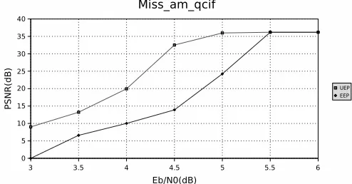
Fig. 8. Comparison of the achievable video PSNR using both EEP and UEP. All system parameters are summarized in Table II
The PSNR performances of both the UEP and EEP system are depicted in Fig. 8. It can be seen that the UEP system attains a near error-free PSNR transmission quality in excess of EbN0 = 2.1 dB. Although at this point the overall BER is about2×10−3, the most sensitive video bits protected by the strongest subcodes are almost error-free. The EEP system reaches the same BER at an EbN0 of about 1.7 dB, but the PSNR attained is significant worse (<14dB). It is also worth noting that for the UEP system, the residual BER becomes so low that it has a negligible effect on the PSNR performance.
TABLE II
THE PARAMETERS OF THE WAVELET-BASED VIDEOPHONE SCHEME.
The system parameters average frame size 2200 bits
Packet size 2000 bits
Packet header size 14 bits
Code rate 1/2
Interleaver length 4000
No. decoder iterations 10
Outer NSC polynomials g0= 1 +D+D2+D4
g1= 1 +D3+D4
Constraint length 5
Precoder polynomials g0= 1 +D
VI. CONCLUSIONS ANDFUTUREWORK
The BBC wavelet-based video codec invoked constitutes the state-of-the art compression schemes, and it achieves a remarkably high reconstructed video quality at a low bit-rate. However, the compressed video sequence is sensitive
to channel errors. When the video frame header,the motion vector header or subband header are corrupted, the decoder loses synchronization with the encoder, and hence UEP was used. The iteratively detected and turbo-equalized IRCC-aided receiver attained an iteration gain of 2 dB over the 5-path dis-persive AWGN of Equation 1 when using a 4000-bit random interleaver. Our future research will consider dispersive fading channels, multilevel modulation and improved AAC schemes.
REFERENCES
[1] C. E. Shannon, ”Coding theorems for a discrete source with a fidelity criterion ”, inIRE National Convention Record, part 4, 1959, pp. 142-163.
[2] ISO/IEC 15444-1:2004, ”JPEG2000 image coding system (2000)”, 2004.
[3] G. Strang and T. Nguyen, ”Wavelet and filter banks”, MA: Wellesley-Cambridge, 1996.
[4] Ingrid Daubechies and Wim Sweldens, ”Factoring Wavelet Transform into Lifting Steps” inJ. Fourier Anal. Appl., vol. 4, num. 3, pp. 247-269, 1998.
[5] L. Hanzo, P. J. Cherriman, and J. Streit, “Wireless Video Communi-cations: Second to Third Generation System and Beyond,” Piscataway, NJ:IEEE Press, 2001.
[6] L. Hanzo, F. C. A. Somerville, and J. P. Woodard, ”Voice Compres-sion and Communications: Principles and Applications for Fixed and Wireless Channels” , IEEE Press, 2001.
[7] L. Hanzo and T. H. Liew and B. L. Yeap,”Turbo coding, turbo equal-isation and space-time coding for transmission over fading channels”, IEEE Press, 2002.
[8] F.Ling, and W.Li, ”Dimensional adaptive arithmetic coding for image compression”, Proceedings of the 1998 IEEE International Symposium on Circuits and Systems, vol 4, Page(s):13-16, June 1998.
[9] R. Koenen, ”MPEG4 Overview,” In IEEE Spectrum, February 1999. [10] J.Wang, N. S. Othman, L.L.Yang, and L.Hanzo, ”Unequal Error
Protec-tion of Speed Data Using Irregular ConvoluProtec-tional Codes” to appear in VTC fall, 2005.
[11] M. Tuchler, and J. Hagenauer, “EXIT charts of irregular codes,” in Pro-ceedings of Conference on Information Science and Systems, Princeton University, Mar. 2002.
[12] S. Brink, “Convergence behavior of iteratively decoded parallel concate-nated codes”, IEEE transactions on communications, vol. 49, No. 10, Oct. 2001.
[13] M. Tuchler, “Design of serially concatenated systems depending on the block length,”IEEE Transactions on Communications, vol. 52, no.2, pp. 209-218, Feb. 2004.
[14] J. Proakis,Digital Communications. New York: McGraw-Hill, 4th ed., 2001.
[15] Sourceforge website: http://sourceforge.net/projects/dirac
[16] T. Acharya, ”A high speed reconfigurable integrated architecture for DWT”, IEEE Global Telecommunications Conference, Vol 2, Page(s):669-673, Nov. 1997.
[17] L. R. Bahl, J. Cocke, F. Jelinek, and J. Raviv, “Optimal decoding of linear codes for minimal symbol error rate,” IEEE Transactions on Information Theory, vol. 20, pp. 284–287, Mar. 1974.
[image:5.595.52.299.145.274.2]