Camilla Colombo
Submitted in fulfilment of the requirements for the Degree of Doctor of Philosophy
Department of Aerospace Engineering Faculty of Engineering
University of Glasgow
NOTE
This thesis contains some figures in .eps. In order to print it out correctely an eps printer is suggested.
Abstract
Many asteroids and comets orbit the inner solar system; among them Near Earth Objects (NEOs) are those celestial bodies for which the orbit lies close, and sometimes crosses, the Earth’s orbit. Over the last decades the impact hazard they pose to the Earth has generated heated discussions on the required measures to react to such a scenario.
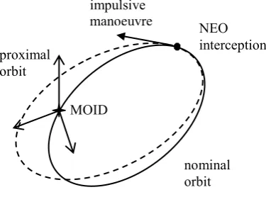
The aim of the research presented in this dissertation is to develop methodologies for the trajectory design of interception and deflection missions to Near Earth Objects. The displacement, following a deflection manoeuvre, of the asteroid at the minimum orbit intersection distance with the Earth is expressed by means of a simple and general formulation, which exploits the relative motion equations and Gauss’ equations. The variation of the orbital elements achieved by any impulsive or low-thrust action on the threatening body is derived through a semi-analytical approach, whose accuracy is extensively shown. This formulation allows the analysis of the optimal direction of the deflection manoeuvre to maximise the achievable deviation.
The search for optimal opportunities for mitigation missions is done through a global optimisation approach. The transfer trajectory, modelled through preliminary design techniques, is integrated with the deflection model. In this way, the mission planning can be performed by optimising different contrasting criteria, such as the mass at launch, the warning time, and the total deflection. A set of Pareto fronts is computed for different deflection strategies and considering various asteroid mitigation scenarios. Each Pareto set represents a number of mission opportunities, over a wide domain of launch windows and design parameters.
Abstract
includes solutions for the deviation of some selected NEOs by means of a solar collector strategy. The semi-analytical formulation derived allows the reduction of the computational time, hence the generation of a large number of solutions. Moreover, sets of Pareto fronts for asteroid mitigation are computed through the more feasible deflection schemes proposed in literature: kinetic impactor, nuclear interceptor, mass driver device, low-thrust attached propulsion, solar collector, and gravity tug. A dominance criterion is used to perform a comparative assessment of these mitigation strategies, while also considering the required technological development through a technology readiness factor.
To my brother Marco
Isaiah 43, 1–3
«Do not be afraid. I’ve redeemed you.
I’ve called your name. You’re mine.
When you’re in over your head, I’ll be there with you.
When you’re in rough waters, you will not go down.
When you’re between a rock and a hard place, it won’t be a dead end
Because I am God, your personal God, the Holy One of Israel, your Saviour.
I paid a huge price for you: all of Egypt, with rich Cush and Seba thrown in!
That’s how much you mean to me! That’s how much I love you!
I’d sell off the whole world to get you back, trade the creation just for you.
Richard Feynman, “The Value of Science”, in Frontiers in Science: A Survey, Ed. E. Hutchings, Basic Books, New York, 1958.
«The same thrill, the same awe and mystery, comes again and again when we
look at any question deeply enough. With more knowledge comes a deeper,
more wonderful mystery, luring one on to penetrate deeper still. Never
concerned that the answer may prove disappointing, with pleasure and
confidence we turn over each new stone to find unimagined strangeness
leading on to more wonderful questions and mysteries - certainly a grand
Acknowledgments
I would like to acknowledge my advisors, Dr. Gianmarco Radice and Dr. Massimiliano Vasile for making this work possible. Their support and guidance have been precious throughout these years. I would like to thank Max, for conveying to me “the same thrill, the same awe and mystery” that make research so beautiful, and for sharing the enthusiasm of working in team. Thank you for the invaluable scientific guidance and the contribution to many of the ideas in this thesis. I would like to thank Gianmarco, for making this extraordinary experience possible. Thank you, for supporting me always e unconditionally, for believing in my abilities and giving me confidence in them. Your positiveness encouraged me and helped me in playing down my worries and insecurities. I am very grateful to each member of the Department of Aerospace Engineering of the University of Glasgow, because the environment has been friendly, supportive and stimulating. I am thankful to the examiners of this thesis, Dr. Victor Becerra and Dr. Jongrae Kim for the fruitful discussion.
For many reasons, my experience of the PhD in Glasgow has been one of the best and strongest in my life, it has changed and extended my visions and strengthened my beliefs. I would like to thank all my colleagues and best friends of the Space Advanced Research Team; you have been wonderful “travel mates”, on every day of this experience. Thank you Pau, I have learnt a lot from the close collaboration with you, saving the Earth from NEOs has been enjoyable together! Thank you Matteo, for being always available, encouraging and supporting me. Thank you for your splendid friendship, Nico, for listening to my thoughts and for sharing with me yours. A big hug and sincere thank-you to Christie, Daniel, Edmondo, Stuart, Imran, Anna, Giulio, Irene, Paola, Matt, Giangi, Nita, DC, Kiran, Tao, my Scottish supporters, Janice, Celia and James. With each one of you I have shared unforgettable precious moments of my Glaswegian experience.
Acknowledgments
even at 1,912 km far away. I am grateful to my parents, for teaching me that good results come from strong commitment and for raising me to chase my dreams. Grazie papi, because with your morning phone calls I experienced that distances are nothing, if you believe so. Grazie mamma, for your constant care, for sharing my feelings and anxieties, and sometimes not sleeping because of them. A big hug to Richi, who shows me his love with no needs for words! Marco, I feel you close to me in every single moment.
I declare that, except where explicitly stated, the work contained in this dissertation is my own.
Contents
Abstract ... iii
Acknowledgments... vii
Contents ... x
List of figures ... xiii
List of tables... xx
Nomenclature ... xxii
List of symbols ... xxii
List of constants... xxx
List of acronyms ... xxx
Chapter 1. Introduction ... 1
1.1. Near Earth Objects and problem definition ... 1
1.2. Research motivations and objectives ... 3
1.3. Background ... 5
1.3.1. Impact hazard ... 5
1.3.2. NEO deflection strategies ... 7
1.3.3. Asteroid deviation ... 10
1.3.4. NEO interception and trajectory optimisation ... 13
1.4. Methodologies developed and implemented... 16
1.5. Dissertation organisation... 20
1.6. Contributions... 21
Chapter 2. Impulsive NEO deflection... 24
2.1. Asteroid deviation problem... 24
2.1.1. Maximum deviation strategies ... 28
2.1.2. Accuracy analysis ... 32
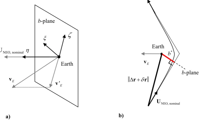
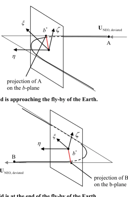
2.1.3. Representation on the b-plane... 35
2.2. Mission options for impulsive deviation... 50
2.2.1. Targets selection ... 50
2.2.3. Results ... 56
2.3. Summary ... 63
Chapter 3. Low-thrust NEO deflection... 65
3.1. Asteroid deviation problem... 66
3.1.1. Analysis of the optimal thrust direction ... 70
3.2. Semi-analytical formulae for low-thrust deviation action ... 72
3.2.1. Latitude formulation ... 73
3.2.2. Periodic variation of the orbital parameters ... 78
3.2.3. Time formulation ... 82
3.3. Mission options for low-thrust deviation ... 89
3.3.1. Targets selection ... 90
3.3.2. Spacecraft model and optimisation problem definition ... 91
3.3.3. Results ... 95
3.4. Summary ... 109
Chapter 4. Comparison of mitigation strategies for hazardous NEOs... 111
4.1. NEO deflection strategies model ... 112
4.1.1. Impulsive action ... 113
4.1.2. Low-thrust action ... 116
4.2. Transfer trajectory... 119
4.3. Multi-criteria optimisation problem formulation ... 120
4.4. Objective function definition ... 123
4.5. Deflection mission options... 126
4.5.1. Targets selection ... 127
4.5.2. Pareto fronts ... 128
4.5.3. Multi-criteria analysis ... 138
4.6. Summary ... 142
Chapter 5. Optimal low-thrust trajectories to asteroids through an algorithm based on differential dynamic programming ... 144
5.1. Differential Dynamic Programming ... 145
5.1.1. Differential dynamic programming for trajectory optimisation.... ... 145
5.2. Modified DDP method... 160
Contents
5.2.2. Mesh definition ... 162
5.3. Algorithm ... 165
5.3.1. Heuristics to improve the convergence rate ... 170
5.4. Local refinement of low-thrust trajectories... 172
5.5. Asteroid rendezvous and fly-by missions ... 177
5.5.1. Rendezvous with asteroid Apophis... 180
5.5.2. Rendezvous with asteroid Apophis from a geostationary transfer orbit ... 187
5.5.3. Fly-by of asteroid 2002 AA29 ... 195
5.6. Summary ... 203
Chapter 6. Conclusions ... 204
6.1. Summary and findings of the thesis ... 204
6.2. Limitations ... 211
6.3. Remarks for future work ... 213
References ... 216
Appendix A. Secular variation of orbital elements due to low-thrust manoeuvre ... 232
A.1. Secular variation of eccentricity over one orbital revolution... 232
A.2. Secular variation of semi-major axis over one orbital revolution... 235
A.3. Secular variation of anomaly of the pericentre over one orbital revolution... 236
A.4. Secular variation of the mean anomaly over one orbital revolution ... 237
List of figures
Figure 2.1: Impulsive NEO deviation. ... 25 Figure 2.2: Components of the optimal v direction for a) asteroid 2000SG344
and b) asteroid 1979XB. ... 30 Figure 2.3: Deviation achieved with || v||=0.07 m/s for a) asteroid 2000SG344 and b) asteroid 1979XB. ... 31 Figure 2.4: Relative error calculated by orbit propagation for asteroid 2000SG344.
... 32 Figure 2.5: Relative error for the deviation of a) asteroid 2000SG344 and b)
asteroid 1979XB... 33 Figure 2.6: Deviation of a) asteroid 2000SG344 and b) asteroid 1979XB... 34 Figure 2.7: Maximum relative error for different asteroids. ... 34 Figure 2.8: Earth-centred local reference system: a) b-plane representation and b) geometry of hyperbolic passage... 35 Figure 2.9: Impact parameter and magnitude of the deviation for 1979XB with v
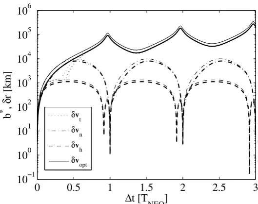
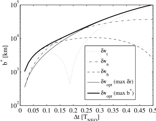
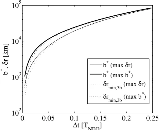
= 0.07 m/s; b*-parameter (bold lines), and deviation (thin lines). ... 37 Figure 2.10: Impact parameter for asteroid 1979XB ∆t<1TNEO: a) strategy of
maximum deviation and b) strategy of maximum b*-parameter. ... 37 Figure 2.11: Impact parameter for asteroid 2000SG344 ∆t<0.5TNEO. Strategy of
maximum deviation (solid line) and maximum b*-parameter (bold line). ... 39 Figure 2.12: Deviation (dashed line) and its projection (bold line) on the b-plane calculated through the two-body problem and minimum deviation computed through the three-body problem (continuous thin line): a) maximum deviation strategy for asteroid 1979XB and b) maximum
List of figures
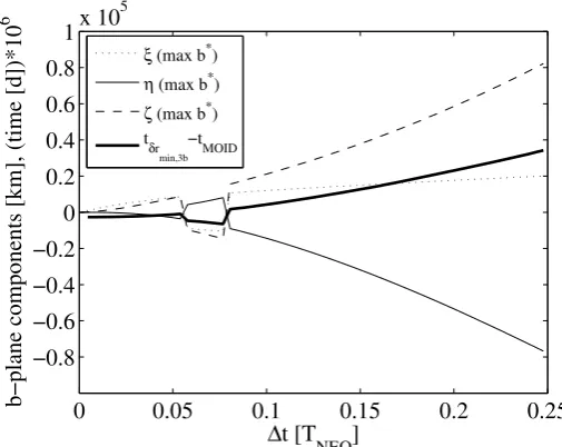
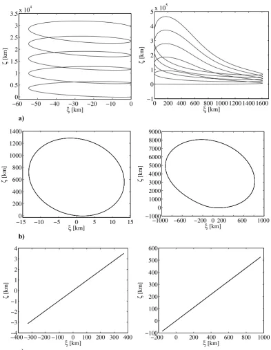
Figure 2.16: Projection on the b-plane of the deviation for asteroid 2000SG344 (left) and asteroid 1979XB (right) with v = 0.07 m/s applied a) along the tangent to the motion, b) along the normal to the motion, and c) along the h-direction. ... 45 Figure 2.17: Projection on the b-plane, function of t for a) asteroid 2000SG344 and b) asteroid 1979XB. ... 46 Figure 2.18: Projection on the b-plane of the deviation. v = 0.07 m/s applied
along the optimal (normal line), the tangent to the motion (dark grey normal line), the normal to the motion (black bold line), and the h
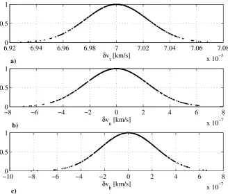
(light grey bold line) directions for a) asteroid 2000SG344 and b) asteroid 1979XB... 46 Figure 2.19: Distribution of the components of v, represented through the
Gaussian membership function, with 3 = vt, mean/100. a) Tangential
component, b) normal component, and c) component along the h
direction... 48 Figure 2.20: Projection on the b-plane of the deviation. vt, mean = 0.07 m/s applied
along the tangent direction with 3 = vt, mean/100 for a) asteroid
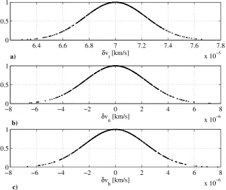
2000SG344 and b) asteroid 1979XB. ... 48 Figure 2.21: Distribution of the components of v, represented through the
Gaussian membership function, with 3 = vt, mean/10. a) Tangential
component, b) normal component, and c) component along the h
direction... 49 Figure 2.22: Projection on the b-plane of the deviation. vt, mean = 0.07 m/s applied
along the tangent direction with 3 = vt, mean/10 for a) asteroid
2000SG344 and b) asteroid 1979XB. ... 49 Figure 2.23: Optimal interception of a) asteroid 1979XB and b) asteroid
1996TC1... 57 Figure 2.24: Optimal interception arguments of latitude for a) asteroid 1979XB
and b) asteroid 1996TC1. ... 57 Figure 2.25: Optimal interception of a) asteroid 2000SB45 and b) asteroid
2002TX55. ... 58 Figure 2.26: Impact velocity function a) of the eccentricity and b) of the
inclination (h-component). ... 58 Figure 2.27: Pareto front for a) asteroid 2000SG344 and b) asteroid 2002GJ8. .. 59 Figure 2.28: Pareto front for asteroid 2002VU17. ... 62 Figure 2.29: Optimal impact ∆v distribution for direct impacts: a) results of the
Figure 3.4: Relative error between the numerical and semi-analytical integration of a) the eccentricity, b) the semi-major axis, and c) anomaly of the pericentre for asteroid Apophis (left) and asteroid 1979XB (right)... 81 Figure 3.5: Relative error between the numerical and semi-analytical integration
of the mean anomaly for a) asteroid Apophis and b) asteroid 1979XB. ... 82 Figure 3.6: Time-formulation algorithm. ... 85 Figure 3.7: Relative error of the time formulation for a) asteroid Apophis
(ka=2.2×10⁵ km3/s2) and b) asteroid 1979XB (ka=2×10⁴ km3/s2). ... 87
Figure 3.8: Relative error on M for a) asteroid Apophis and b) asteroid 1979XB. ... 88 Figure 3.9: Percentage of savings in computational time by using the
semi-analytical time formulation with respect to the numerical integration of Gauss’ equations. a) Asteroid Apophis and b) asteroid 1979XB. . 89 Figure 3.10: Magnitude of the acceleration for Apophis. ... 92 Figure 3.11: Launch opportunities for a deviation mission to Apophis. The colour scale represents the value of the achieved deviation at the MOID. ... 96 Figure 3.12: Deviation mission to Apophis: a) Pareto front. Launch mass, warning time and magnitude of the deviation are represented on the three axes. b) Achieved deviation as a function of the time length of the thrust arc. ... 97 Figure 3.13: Orbit and MOID characteristics for different values of semi-major
axis starting from Apophis case: a) asteroid orbits and b) true anomaly of the MOID. ... 98 Figure 3.14: Sensitivity of the deviation to the semi-major axis: a) deviation
achieved for orbits with different values of semi-major axis and for increasing values of thrust interval and b) relative error for different values of semi-major axis. The white line represents Apophis case (a = 0.922 AU)... 99 Figure 3.15: Orbit and MOID characteristics for different values of eccentricity
List of figures
Figure 3.19: Orbit and MOID characteristics for different values of semi-major axis starting from 1979XB case: a) asteroid orbits and b) true anomaly of the MOID. ... 103 Figure 3.20: Sensitivity of the deviation to the semi-major axis: a) deviation
achieved for orbits with different values of semi-major axis and for increasing values of thrust interval and b) relative error for different values of semi-major axis. The white line represents 1979XB case (a = 2.350 AU)... 104 Figure 3.21: Orbit and MOID characteristics for different values of eccentricity
starting from 1979XB case: a) asteroid orbits and b) true anomaly of the MOID. ... 105 Figure 3.22: Sensitivity of the deviation to the eccentricity: a) deviation achieved for orbits with different values of eccentricity and for increasing values of thrust interval and b) relative error for different values of eccentricity. The white line represents 1979XB case (e = 0.726).... 106 Figure 3.23: Launch opportunities for a deviation mission to Castalia. The colour scale represents the value of the achieved deviation at the MOID. . 106 Figure 3.24: Deviation mission to Castalia: a) Pareto front. Launch mass, warning time and magnitude of the deviation are represented on the three axes. b) Achieved deviation as a function of the time length of the thrust arc. ... 107 Figure 3.25: Launch opportunities for a deviation mission to Itokawa. The colour scale represents the value of the achieved deviation at the MOID. . 108 Figure 3.26: Deviation mission to Itokawa: a) Pareto front. Launch mass, warning time and magnitude of the deviation are represented on the three axes. b) Achieved deviation as a function of the time length of the thrust arc. ... 108 Figure 4.1: Orbit of the selected asteroids: a) 2D view, and b) 3D view... 128 Figure 4.2: Pareto front for the deviation of asteroid Apophis through different
strategies: a) kinetic impactor, b) nuclear interceptor, c) mass driver, d) attached spacecraft propulsion, e) solar collector, and e) gravity tractor. ... 132 Figure 4.3: Pareto front for the deviation of asteroid Itokawa through different
strategies: a) kinetic impactor, b) nuclear interceptor, c) mass driver, d) attached spacecraft propulsion, e) solar collector, and e) gravity tractor. ... 134 Figure 4.4: Pareto front for the deviation of asteroid Castalia through different
strategies: a) kinetic impactor, b) nuclear interceptor, c) mass driver, d) attached spacecraft propulsion, e) solar collector, and e) gravity tractor. ... 136 Figure 4.5: Pareto front for the deviation of asteroid 1979XB through different
Figure 5.2: Control law schedule according to Jacobson’s algorithm. ... 150 Figure 5.3: Trajectory associated to the control law in Eq. (5.12)... 150 Figure 5.4: Control law during the convergence process. Direct transfer Earth to
Mars, with a time of flight of 200 days. ... 151 Figure 5.5: Trajectory discretisation within the optimisation problem... 161 Figure 5.6: Trajectory discretisation in the Static/Dynamic Control approach. The grey arrows show that the control is kept constant within a segment. ... 162 Figure 5.7: Modified DDP algorithm... 169 Figure 5.8: Pareto front for a deviation mission to asteroid Apophis. ... 174 Figure 5.9: Points of the Pareto front locally optimised through the DDP method.
... 175 Figure 5.10: Percentage of propellant mass saved through the local optimisation of the solutions. ... 176 Figure 5.11: Thrust magnitude. The dashed line represents the first guess solution provided to the DDP algorithm, the continuous line is the optimal thrust profile. a) Entire trajectory and b) close-up on the escape phase. ... 181 Figure 5.12: Time evolution of the thrust components. ... 181 Figure 5.13: Mass. The dashed line represents the first guess solution; the
continuous line is the optimal profile... 182 Figure 5.14: Rendezvous trajectory to Apophis represented in the Earth inertial
reference frame. a) Entire trajectory and b) close-up on the escape phase... 183 Figure 5.15: Trajectory to Apophis rendezvous. Transfer in the Sun inertial
reference frame. The dashed line represents the first guess transfer solution; the continuous line is the optimal trajectory. Apophis and Earth orbit are represented respectively in red and blue continuous lines. ... 184 Figure 5.16: Evolution of the Keplerian elements during the escape phase. The
dashed line represents the first guess solution; the continuous line is the optimal profile. a) Semi-major axis expressed in Earth radii, b) eccentricity and c) inclination. ... 185 Figure 5.17: Time of flight sensitivity. The integral term of the cost function
(normalised to the weight parameter w) is represented on the y axis. Each point represents an optimised transfer (with final constraints satisfied) with a given time of flight. The cross shows the result corresponding to the solution fully presented in this section. ... 186 Figure 5.18: Thrust magnitude for the mission with m0 = 1350 kg. The dashed line
List of figures
Figure 5.19: Mass for the mission with m0 = 1350 kg. The dashed line represents
the first guess solution; the continuous line is the optimal profile... 187 Figure 5.20: Mass. The dashed line represents the first guess solution; the
continuous line is the optimal profile... 189 Figure 5.21: Thrust magnitude. The dashed line represents the first guess solution provided to the DDP algorithm, the continuous line is the optimal thrust profile. a) Entire trajectory and b) close-up on the escape phase. ... 189 Figure 5.22: Time evolution of the thrust components. ... 190 Figure 5.23: Evolution of the instantaneous eccentricity with time during the
spiralling-out phase. The dashed line represents the first guess, the continuous line is the optimal solution... 190 Figure 5.24: Close-up on the escape phase. The dashed line represents the first
guess, the continuous line is the optimal solution... 191 Figure 5.25: Trajectory to Apophis rendezvous. The dashed line represents the
first guess transfer solution; the continuous line is the optimal trajectory. a) Transfer in the Earth inertial reference frame. The circle represents the target position, the cross is the final state of the optimal trajectory. b) Transfer in the Sun inertial reference frame. Apophis and Earth orbit are represented respectively in red and blue continuous lines. ... 192 Figure 5.26: Fly-by of the Earth. The cross represents the pericentre of the
hyperbola with respect to the Earth. a) Fly-by phase and b) close-up of the passage from the pericentre of the hyperbola... 193 Figure 5.27: Evolution of the thrust and velocity magnitude during the fly-by. The dashed line represents the first guess solution; the continuous line is the optimal profile. The cross symbol is in correspondence of the pericentre passage. a) Thrust magnitude and b) velocity magnitude with respect to the Earth... 194 Figure 5.28: Evolution of the angles of the velocity vector with respect to the
Figure 5.32: Time evolution of the thrust components. ... 197 Figure 5.33: Mass. The dashed line represents the first guess solution; the
continuous line is the optimal profile... 198 Figure 5.34: Trajectory to 2002 AA29 fly-by represented in the Earth inertial
reference frame. a) Entire trajectory and b) close-up on the escape phase... 199 Figure 5.35: Evolution of the Keplerian elements during the escape phase. The
dashed line represents the first guess solution; the continuous line is the optimal profile. a) Semi-major axis, b) eccentricity, c) inclination, and d) anomaly of the ascending node. ... 200 Figure 5.36: Lagrange point passage. The cross highlights the position of the
Lagrange point L2 when the trajectory changes its inclination. ... 201 Figure 5.37: Angles of the thrust vector. The dashed line represents the first guess solution; the continuous line is the optimal profile. a) Right ascension and b) declination. ... 201 Figure 5.38: Acceleration components. The dashed line represents the first guess solution, the continuous line is the optimal solution. The black line indicates the acceleration due to the Earth’s gravity field, the black bold line indicates the disturbing acceleration due to the Sun and the bold grey line indicates the thrust acceleration. a) Acceleration magnitude, b) x component of the acceleration, c) y component of the acceleration, and d) z component of the acceleration. ... 202 Figure 6.1: Comparison between the approximated low-thrust model and the
List of tables
Table 2.1: Physical parameters for considered NEOs... 52
Table 2.2: Optimal launch opportunities for a direct transfer to selected asteroids as a result of the multi-objective optimisation. ... 60
Table 2.3: Optimal launch opportunities for transfers to selected asteroids via a single Venus swing-by as a result of the single-objective optimisation. ... 63
Table 3.1: Computational time of the analytical and numerical approach. ... 78
Table 3.2: Maximum relative error between the numerical and semi-analytical integration. ... 80
Table 3.3: Asteroids orbital and physical parameters. ... 90
Table 3.4: Mission characteristics... 91
Table 3.5: Acceleration constant and average of the accelerations acting on the asteroid. ... 92
Table 4.1: Margins on the wet mass into orbit for the different deviation strategies. ... 124
Table 4.2: Search domain for the multi-objective optimisation... 126
Table 4.3: Asteroids orbital and physical parameters. ... 127
Table 4.4: Strategy dominance for asteroid Apophis... 140
Table 4.5: Strategy dominance for asteroid Itokawa. ... 140
Table 4.6: Strategy dominance for asteroid Castalia. ... 140
Table 4.7: Strategy dominance for asteroid 1979XB... 141
Table 5.1: Mission characteristics... 173
Table 5.2: Mission characteristics... 180
Table 5.3: Parking orbit parameters. ... 188
Table 5.4: Mission characteristics... 188
Table 5.5: Mission characteristics... 195
Table B.1 : Technology readiness levels. ... 243
Table B.2 : TRL for the different mitigation schemes... 243
Table B.3 : TRL mapping into required time to fully develop the required technology. ... 245
Nomenclature
List of symbols
Latin symbols
k
A Matrix of the DDP algorithm at stage k. MOID
A Matrix form of the proximal motion equations.
a Acceleration vector, km/s2, or coefficient matrix of the Runge-Kutta-Fehlberg integration scheme.
a Semi-major axis, km. AU Astronomical unit, km.
k
B Matrix of the DDP algorithm at stage k.
b Coefficient matrix of the Runge-Kutta-Fehlberg integration scheme.
b Semi-minor axis, km. *
b Impact parameter, km. l
b Lower boundary for the solution vector of the global optimisation. u
b Upper boundary for the solution vector of the global optimisation. k
C Matrix of the DDP algorithm at stage k.
C Constraint.
c Coefficient matrix of the Runge-Kutta-Fehlberg integration scheme.
c Constant.
k
D Matrix of the DDP algorithm at stage k.
D Domain.
d Hovering distance, m. m
d Diameter of the mirror, km. tr
d Index associated to the transfer trajectory. k
E Matrix of the DDP algorithm at stage k.
e Eccentricity. r
e Relative error.
F Incomplete elliptic integral of the first kind. f Discrete-time state transition function.
f Function containing the continuous dynamics equations. d
G Matrix form of the Gauss’ equations, considering an impulsive change in the velocity.
t
G Matrix form of the Gauss’ equations, considering an impulsive change in the velocity at time t.
G Universal gravity constant, km3/(kg·s2).
g Scalar stage-wise loss function. 0
g Standard free-fall, km/s2. k
H Matrix of the DDP algorithm at stage k. ˆ
h Unit vector in the direction of the angular momentum.
h Angular momentum, km2/s. k
h Discretisation step. d
I Dominance index. sp
I Specific impulse of the spacecraft engine, s. m
Identity matrix of size m.
i Inclination, rad or deg, or integer number. NEO
id Near Earth object identification number.
J Vectorial (multi-criteria) cost function of the optimisation problem.
J Cost function of the optimisation problem.
j Integer number. k
K Matrix of the DDP algorithm at stage k.
k Integer number or integer number indicating the generic stage of DDP and the decision time of the trajectory at which the control law is allowed to change.
a
Nomenclature
lim
k State from which the new control law is adopted for the integration of the dynamics.
L True longitude, rad.
l Number of components of the Lagrange multiplier vector.
M Mean anomaly, rad or deg.
m Mass of the spacecraft, kg, or number of components of the objective function, or number of components of the control vector.
0
m Mass of the spacecraft into space, kg. d
m Dry mass or mass of the spacecraft at the asteroid interception, kg. p
m Propellant mass, kg. NEO
m Mass of the near Earth object, kg. shot, j
m Mass expelled per shot j by the mass driver strategy, kg.
N Total number of decision times or control stages of the DDP algorithm.
p
N Set of indices of feasible solutions in the population in the global optimisation problem.
n Angular velocity, s–1, or number of components of the state vector. rev
n Number of revolutions around the central body.
ˆ
n Unit vector in the normal direction in the orbital plane. k
P Matrix of the DDP algorithm at stage k.
P x Property of x.
p Semilatus rectum, km. k
Q Matrix of the DDP algorithm at stage k. R General rotation matrix.
k
R Matrix of the DDP algorithm at stage k. Earth
R Radius of the Earth, km. Earth-Moon
R Earth–Moon distance, km. r Position vector, km.
r Norm of the position (orbital radius), km. a
p
r Pericentre distance, km.
reltol Relative tolerance.
mesh
reltol Relative tolerance on the mesh selection. k
S Matrix of the DDP algorithm at stage k.
s State vector.
s Deviation strategy. T Thrust vector, N.
NEO
T Orbital period of the NEO, days.
ˆ
t Unit vector in the tangential direction in the orbital plane.
t Time, s or days. 0
t Departure time from the Earth, s or days. d
t Time at which the impulsive deviation manoeuvre is performed, s or days.
e
t Time when the low-thrust arc ends, s or days. f
t Final time of the transfer trajectory, s or days. i
t Interception time and time when the low-thrust deflection manoeuvre is performed, s or days.
MOID
t Time at the minimum orbit intersection distance point, s or days. w
t Warning time, s or days.
ToF Time of flight, s or days. r
tol Absolute tolerance on the position error. v
tol Absolute tolerance on the velocity error. NEO
U Unperturbed velocity of the asteroid relative to the Earth, km/s.
u Control vector.
v Orbital velocity vector, km/s.
V Optimal return function of the DDP algorithm.
V Average velocity of evaporated particles, m/s.
v Norm of the orbital velocity, km/s. e
Nomenclature
w Weight parameter.
w Weight parameter.
X Set of feasible solutions of the global optimisation problem. front.
y
. Cartesian coordinate along the z axis.
G ek symb
x Generic vector or solution of the Pareto
x Cartesian coordinate along the x axis. Cartesian coordinate along the y axis. k
Z Matrix of the DDP algorithm at stage k z
re ols
Vector of the orbital parameters.
In-plane angle of the velocity vector, rad or deg. Coefficient vector of the feedback control law
k component proportional
to the variation of the state vector at stage k.
k Coefficient vector of the feedback control law component proportional vector at stage k.
to the variation of the Lagrange multiplier
NEO from Earth at the minimum orbit
p a technology, y or days. Momentum enhancement factor.
Vector distance of the r
intersection distance, km.
r
Norm of r, km. T
t
R Time interval required to develo v Relative velocity vector, km/s.
Out-of plane angle of the velocity vector, rad or deg. r Deviation vector, km.
r
Norm of r, km.
s
Component of the deviation vector, km. v Impulsive manoeuvre vector, km/s.
v
Norm of v, km/s. ˆopt
v Optimal impulse unit vector.
Orbital elements difference between the perturbed and the nominal orbit.
ˆ Unit vector in the direction opposite to the projection of the heliocentric velocity of the planet onto the b-plane.
ˆ Unit vector in the direction perpendicular to the b-plane aligned along the unperturbed velocity of the NEO relative to the Earth.
k
Difference between the optimal return function at state k applying the new control, and the optimal return function at state k applying the nominal control.
True anomaly, rad or deg. *
Argument of latitude, rad or deg. Vector of Lagrange multipliers.
Gravitational constant, km3/s2. Eigenvector of the transition matrix.
ˆ Unit vector in the b-plane that completes the reference system
. Shape parameter of the shape-based method for low-thrust trajectories.
Scattering factor. Transition matrix.
Angle between the pointing direction of the engines of the gravity tug, and the line between the spacecraft and the NEO centre of mass, rad.
Scalar function representing the constrains on the final stage in the optimal control problem.
Argument of the ascending node, rad of deg. Argument of the perigee, rad or deg.
Subscripts
1 Initial condition of a variable.
d Value calculated at the instant the deviation manoeuvre is performed.
Nomenclature
h Vector component in the direction perpendicular to the orbit plane, in the direction perpendicular to the osculating angular momentum of the orbit.
i Value calculated at the time of the NEO interception.
k Stage of the DDP procedure.
MOID Value calculated at the Minimum Orbit Intersection Distance. mean Mean value.
n Vector component in the normal direction in the orbit plane.
out Threshold value to exit a computational loop.
r Vector component in the radial direction in the orbit plane.
s Derivative with respect to the state vector s.
s/c Spacecraft.
t Vector component in the tangential direction in the orbit plane.
target Variable related to the target body.
u Derivative with respect to the state vector u.
x Vector component along the Cartesian x axis.
y Vector component along the Cartesian y axis.
z Vector component along the Cartesian z axis.
Vector component in the transversal direction in the orbit plane.
Superscripts
* New nominal control for the DDP algorithm with global variation in control.
k Stage of the DDP procedure.
Mathematical notation
Arbitrary variable. Nominal value of .
Value of computed on the deviated orbit.
d dt
Time derivative of over time.
f Function of .
(Differential) variation of . T
Transposed of . 1
Inverse of .
exp Exponential of . ˆ
Unit vector in the direction of . 2-norm of .
Norm infinity of the vector .
k Sequence of variable in time. QP Linear quadratic part of the Taylor expansion of the function . s
Gradient of the scalar function , or Jacobian of the vector function with respect to the state s.
ss
Block components of the Hessian matrix of the scalar or the vector function with respect to the state s.
us
Block components of the Hessian matrix of the scalar or the vector function with respect to the control u and the state . s
u
Gradient of the scalar function , or Jacobian of the vector function with respect to the control u.
uu
Block components of the Hessian matrix of the scalar or the vector function with respect to the control u.
Dominance.
Is much less than.
Cross product or symbol used to define the dimension of a vector/matrix.
Equal approximately to. 1, 2
Scalar product between the vectors and 1 2.
| Such that.
Cardinality of a set. Is an element of.
Is a subset of.
Nomenclature
For all, for any.
Material implication. Assignment (in an algorithm). Set of real numbers.
min Minimisation problem. max Maximisation problem.
List of constants
Astronomical Unit distance AU = 1.495978707 × 10⁸ km Universal gravity constant G = 6.67259 × 10⁻²⁰ km3/(kg·s2) Standard-free fall g0 = 9.80665 m/s2
Radius of the Earth REarth = 6378.16 km Earth–Moon distance REarth-Moon = 384,401 km
Earth gravitational constant Earth = 3.986004461921757 × 10⁵ km3/s2 Sun gravitational constant Sun = 1.327244876900 × 10¹¹ km3/s2
List of acronyms
AIAA American Institute of Aeronautics and Astronautics.
AU Astronomical Unit.
CPU Central Processing Unit.
DDP Differential Dynamic Programming. ESA European Space Agency.
JAXA Japan Aerospace Exploration Agency. JPL Jet Propulsion Laboratory.
LEO Low Earth Orbit.
GEO Geosynchronous Earth Orbit. GTO Geostationary Transfer Orbit.
MJD2000 Modified Julian Day since 2000 (counted since 1st of January 2000 at 12:00 pm).
MOID Minimum Orbit Intersection Distance.
NASA National Aeronautics and Space Administration. NEA Near Earth Asteroid.
Chapter 1.
Introduction
Near Earth Objects (NEOs) interception and hazard mitigation has been recognised as a key issue for the safety of life on Earth. This thesis will respond to this requirement and will develop methodologies to allow the interception and deviation of potentially hazardous asteroids and comets.
In this chapter we will introduce the motivations and objectives of the study. Subsequently, a summary of the current state of the art in asteroid deflection and interception will be given. After a brief overview on the impact hazard, we will present the deflection strategies proposed in literature. In particular, the analysis will focus on methods to compute the variation of the asteroid course following a deflection manoeuvre. In this context, we also review some analytical models for low-thrust trajectory design and investigate their application to the computation of the diverted trajectory of the NEO.
For the study of asteroid interception, an overview of various approaches for low-thrust trajectory optimisation is given. A brief discussion of direct and indirect approaches, in order to highlight the reasons which led us to the selection of the differential dynamic programming technique for the design of interception transfers to NEOs, is also performed.
Finally, a summary of the methodologies developed and implemented in this study is provided.
1.1.
Near Earth Objects and problem definition
1.1. Near Earth Objects and problem definition
in the solar system [1], and the number increases as astronomical surveys continue. Among the family of asteroids and comets, Near Earth Objects* are those bodies that have been attracted by the gravity of the other planets into orbits, which bring them near the Earth’s, with a perihelion distance less than 1.3 AU. These celestial bodies, which travel at very high velocity relative to the Earth, range in size from pebbles to kilometres-diameter objects.
Near Earth objects have been generating growing scientific interest because, as primordial remnants of our solar system, they preserve precious information about its formation, composition and evolution; besides, their collision with the early Earth, would have influenced the shape and composition of our planet. Some NEOs are especially attractive targets for low-cost missions, because of their orbital accessibility with current technologies and short flight duration. This suggests their use for the exploitation of raw materials and for the settlement of future bases, to extend the human exploration to Mars and beyond [2],[3].
Nevertheless, NEO collision with the Earth represents a possible risk to mankind. A short-term threat is posed by a large number of small asteroids, which could cause local devastating effects to our planet. On the other hand, impact hazards with global catastrophic consequences could occur, on a long-term, if a larger kilometre-sized body were to hit the Earth [4]. Advances in orbit determination and theoretical studies on hazard characterisation have increased the capability of predicting potential impacts. A subcategory of NEAs is defined Potentially Hazardous Asteroids (PHAs), which have a non-zero probability of collision with the Earth. This is determined accordingly to their orbital parameters and absolute magnitude; specifically, objects with a Minimum Orbit Intersection Distance (MOID) from the Earth’s orbit equal or less than 0.05 AU (i.e., approximately 7,480,000 km) and a diameter larger than 150 meters (which is equivalent to an absolute magnitude of 22.0 or less [2]) are considered potentially hazardous objects. There are currently 1105† known PHAs [5].
*
The definition of Near Earth Objects includes Near Earth Asteroids (NEAs) and Near Earth Comets, which are comets with a period less than 200 years. Within this dissertation we will often use the term asteroid alone; however, except where explicitly stated, the techniques developed can be applied to either class of celestial bodies.
†
The impact hazard raises major issues, among them the need to increase the present knowledge of the orbits and physical properties of such bodies, to accurately assess (after initial observation) the likelihood of a collision with the Earth well in advance, the inadequacy of current techniques and technologies necessary for mitigation, disaster management, politics and policy of planetary defence, and communication with the public. Moreover, careful thought is required to investigate options for fast and efficient interception of a potentially dangerous NEO and for minimising or removing the threat it poses. Several organisations and governments have recognised the threat of asteroid hazard and have established discussion panels on the state of the art and the issues of NEO discovery and characterisation, available deflection systems, current and future mitigation and study missions and technologies, impact hazard and effects, involvement of the general public, political and policy implications [6]. The outcome of these works is a series of recommendations and steps that should be followed by the international community to undertake a program on planetary defence [7],[8]. In Great Britain a debate took place in the House of Commons in March 1999 and a Task Force to the Minister for Science to report on potentially hazardous near Earth objects was established in January 2002. The Task Force, which released its findings in September 2000, stated that “We recommended that the Government, with other governments, set in hand to studies to look into the practical possibilities of mitigating the results of impact and deflecting incoming objects” [9].
Over the last decades significant efforts have been devoted to the monitoring [10],[11] and cataloguing of potentially hazardous objects, together with a continuous update of the risk assessment related to each potential hazardous object [12]–[15], but little research has been carried out to assess how to act and react in the case of a NEO travelling on a collision course with the Earth.
1.2.
Research motivations and objectives
1.2. Research motivations and objectives
Several deviation strategies have been proposed and the space community is discussing the current capabilities for NEO mitigation. Therefore, the first objective is to develop a formulation of the asteroid deviation problem, which allows assessing the effectiveness of any proposed mitigation strategy. The general applicability of this formulation is desired to model the effect of various deflection strategies and to accommodate to the wide range of orbital elements of NEOs. Moreover, high accuracy is essential in predicting the variation of the displacement of the asteroid, achieved through the application of a deflection action on it.
The second objective is to study methodologies for the design of optimal transfers to the interception of dangerous NEOs. In fact, in order to assess the effectiveness and efficiency of a mitigation strategy, the complete mission has to be modelled. Moreover, for the selection of optimal launch opportunities, the two main phases of the mission, namely interception and deflection phase, have to be linked into an integrated design. For example, the total mass of the spacecraft into orbit and the warning time (i.e., elapsed time between the date the mission is launched from the Earth and the date of the hazard impact) should be minimal for a given deviation achievable. Instead of designing a single mission scenario, a more general approach hinges on the analysis of families of optimal opportunities, according to different criteria. In computational terms, this translates in exploring a wide domain of design parameters and hence requires the use of preliminary design techniques (usually under the hypothesis of two-body problem dynamics), for fast modelling the transfer leg.
At a second stage, once a set of first guess solutions for the overall mission has been identified, a selected number of refined trajectories can be optimised, using a more accurate model of the system dynamics. In this context, this research aims to study and develop techniques for the solution of the optimal control problem associated to the design of low-thrust trajectories. The principal requirements are accuracy in reproducing the trajectory, in order to fully exploit the dynamics of the problem within the optimisation process, and robustness, to converge even when a poor first guess solution is available.
launch dates. Moreover, the purpose is to perform a comparative assessment of the more feasible mitigation strategies proposed in literature, in order to evaluate their efficiency and technology readiness. In order to perform a comprehensive analysis, to compare the various deflection strategies according to a wide number of mitigation scenarios, in terms of target NEOs and mission design parameters, a method will be defined.
1.3. Background
1.3.1. Impact hazard
The Earth, as with most of the planets of the solar system, from its formation up to recent times, has experienced a strong interaction with minor celestial bodies such as asteroids and comets. This is testified by the numerous craters on the Moon and other planets [16].
The over 170 impact structures or craters recognised around the globe provide scientific evidence that such astronomical events have repeatedly occurred in the past [17], though in many cases the erosion and the movement of the terrestrial plates cancelled their sign.
1.3. Background
has been estimated to be larger than 1 km and is estimated that the number of such objects is around 1000 [21].
If these large size bodies are extremely rare, on the other hand objects with diameter greater than 40 m, which is considered the critical threshold above which the Earth’s atmosphere is no longer disintegrating an object, are estimated to be more than one million in number, with a statistical frequency of impact of one hundred years or even less. An example of such an event happened at the beginning of the twentieth century in Siberia, where an object of few tens of meters, though disintegrating before hitting the ground, pulverised many square kilometres of the Siberian forest [22],[23]. An equivalent impact in a densely populated area would have locally devastating effects [4].
Though the concern for hazard from impact of comets was first expressed by Halley in 1705 [24], the threat of an asteroid hitting the Earth has been recognised and accepted only over the last decades, and sometimes brought to the attention of a wider public, for example through spectacular events such as the collision of fragments of the comet Shoemaker-Levy 9 with Jupiter in 1994 [25]. The discovery of Apophis (for which an impact in 2029 has been definitively excluded, through a passage in a keyhole during the 2029 fly-by could still lead to an impact in 2036‡ [26]) has drawn the attention of public and media to the issue of potentially hazardous objects, and, consequently, to the technological and detection capabilities that nations have in order to implement a mitigation and prevention policy.
At the same time, space agencies have started widening their scope to comets and asteroids not only to improve the current knowledge of these small celestial bodies, but also to develop the technological capabilities required in case an object should pose a serious threat to the Earth. Several fly-by, rendezvous or sample return missions to asteroids and comets have been scheduled to track their position and velocities, map the surface, determine size, shape, mass, rotation rate, density, gas and dust emission and characterise their chemical composition and structure. Past missions such as Giotto (ESA) [27], Deep Impact (NASA) [28], NEAR-Shoemaker (NASA) [29], Deep Space 1 (NASA) [30],[31], Galileo
‡
(NASA) [32], Stardust (NASA) [33], present missions like Rosetta (ESA) [34], Hayabusa (JAXA) [35], and future missions like Dawn (NASA) [36] testify the interest of space agencies in scientific exploration of the solar system. In particular, the European Space Agency is now assessing the feasibility of Don Quijote asteroid deflection precursor mission [37],[38], which plans to impact a spacecraft with a high relative velocity onto an asteroid and measure its deflection. Should this mission launch, this would be the first technological demonstration of our capability to deviate an asteroid if needed.
1.3.2. NEO deflection strategies
During the last decades a number of possible strategies to prevent a collision of a potentially hazardous object with Earth have been proposed [39],[6]. Most of them consider a change in linear momentum of the asteroid, with a consequent variation in its nominal orbit, this resulting in an increase of the distance of minimum displacement of the object from the Earth. The mitigation strategies reviewed in the literature can be catalogued depending on their interaction with the asteroid, as:
Strategies producing an impulsive change in the linear momentum of the asteroid, such as kinetic impactors or nuclear interceptors;
Strategies producing a multi-impulsive change in the linear momentum of the NEO by ejection of material, such as mass drivers;
Strategies actively producing a low-thrust, such as attached propulsion devices, ablation-based technologies, gravity tractors;
Strategies passively producing a low-thrust by inducing thermo-optical changes of the asteroid surface.
1.3. Background
stand-off explosion, occurring at a certain distance from the NEO, is more robust against the uncertainties on asteroid materials, components, shape, etc. On the other hand, the use of nuclear explosives in space is banned by the Outer Space Treaty [46] and the misuse of this deflection system could pose a higher risk than the probability of NEO collision with Earth [47].
Systems like kinetic impactors and nuclear interceptors will deliver an impulse that will change the asteroid orbit or break it into fragments [48],[49]. Strategies relying on kinetic impact or nuclear explosion can achieve the threat mitigation either by diverting the asteroid or comet course, or by destroying it in space with a single explosive charge on, or, below the surface. This latter option, however, is a critical strategy, as the asteroid could only fragment and still impact the Earth and potentially cause more damage [50],[51].
Mass drivers deliver a multi-impulsive change in the linear momentum of the NEO by collecting material from the asteroid surface and ejecting it away from the asteroid. The effect is equivalent to the steam of an engine device; the only difference is the use of in-situ material (material from the asteroid surface) as propellant [52].
which is concentrated onto the asteroid surface, producing the vaporisation of the surface [59],[60]. Ablation-based strategies produce a beam of ejected material that would act as a thrust according to the Newton’s third law.
Coating the surface of the asteroid is used to alter the albedo and modify the induced Yarkovsky acceleration [61]. The resulting thrust is small compared to other schemes, especially for increasing NEO size.
A small number of authors have performed a partial comparative assessment of the numerous proposed mitigation strategies. Some of these emphasise a classification system based on effectiveness in acting near instantaneously on the hazard, or producing a long duration continuous effect [62]. Some considerations on the capabilities of current technologies (i.e., near-term, medium-term or long-term strategies) were also included in the discussion; however, simplified dynamics model were used to asses the required velocity increment for the deflection (for example, the deflection manoeuvre is assumed applied at the pericentre of the NEO’s orbit). Other authors classified various mitigation strategies on the basis of the coupling between the dynamics of the deflection of the object and the guidance of the spacecraft [63]. The approximation of the control delivered by the spacecraft to the NEO depends on the motion of the two bodies and on the deflection mechanism capabilities. Three main categories of strategies are identified, respectively based on cratering of the NEO, continuous mass ejection or on action at distance, such as exploiting solar pressure, with solar sails or paint.
1.3. Background
were identified, representing different sizes of threat. The system performance was described as the “effective momentum change” (i.e., ∆v required for the deflection multiplied by the NEO’s mass) and the launch performance (i.e., deflection vehicle launch mass) to place the payload into an intercept trajectory.
Finally Rogers and Izenberg [65] used the normalised specific impulse of the divert technology (defined as the ratio of the impulse imparted to the weight-on-Earth of the strategy) as a qualitative way of comparing the efficiency of various mitigation strategies.
1.3.3. Asteroid deviation
In order to determine the variation of the displacement of the NEO, following the application of any of the proposed strategies, it is convenient to classify them according to the equivalent action they deliver to the body. The effect all the proposed deflection strategies have on the asteroid can be distinguished either as an impulsive or nearly instantaneous variation of the velocity of the asteroid, or as a low-thrust, if they act on the asteroid over an extended period of time, with a continuous momentum change [6]. Hence in the following of this study, they will be distinguished between impulsive strategies (e.g., kinetic impactor, nuclear interceptor. Mass driver can be considered as a multi-impulsive strategy, even if its effect is comparable to the deviation produced by a continuous action) or low-thrust strategies (e.g., solar collector, pulsed laser, gravity tractor, enhanced Yarkovsky effect, etc.).
The consequent variation of the orbit of the asteroid can be computed through a numerical procedure, and the result has to be validated through orbit tracking and astronomical observations. Carusi et al. [40] studied the v
increases the performance. The issue with numerical approaches is the computational time, which becomes a limit when the trajectory has to be integrated over a long period without losing accuracy. Of course, in the case of a real event, the CPU time would not be an issue; nonetheless, a number of authors have developed analytical formulations to make extensive investigations and gather useful lessons from the computation of a wide range of solutions. In this case the simplification of the two-body problem is often adopted.
Ahrens and Harris [67] gave an estimation of the v required for deflecting an asteroid from an Earth-crossing orbit, by perturbation either perpendicular or along the direction of motion, and Scheeres and Schweickart [68] derived an analytical expression of the shift in the position of the asteroid, under the assumption of a circular orbit and a constant acceleration aligned with the velocity of the NEO. This strategy, which yields a change in the mean motion of the asteroid, is proposed for long lead time until the impact. Subsequently, Izzo [69] proposed a similar solution, but extended it to non circular orbits. However, this formulation introduces an integral term that was solved analytically only in the case of an impulsive deflection manoeuvre. Furthermore, the effect of the deviation strategy is translated in a change of mean motion and hence in a phase shift; other changes in the orbital geometry are not included.
1.3. Background
remains in the range 150–180 deg for warning times longer than one asteroid period, regardless of the orbital elements of the asteroid.
Low-thrust analytical models
The attention is now focused on NEO deviation by technologies delivering a continuous low-thrust action. In particular, when the objective is the identification of many mission opportunities (i.e., favourable conditions for deflection), global optimisation techniques can be employed, to perform an extensive search for optimal solution over a search space. In this case, the evaluation of several tens of thousands of trajectories is required, thus the numerical computation of the deflected course of the asteroid would be impractical.
Since 1950 [76]–[78], several authors have proposed analytical solutions for some particular cases of low-thrust control problems. Tsien [77] and Benney [78] developed a solution for escape trajectories, respectively, subject to radial and tangential continuous thrust acceleration. Following a similar formulation, Boltz [79],[80] proposed a solution in case the ratio between the thrust and the gravity acceleration is kept constant. In both cases, the orbit is assumed to be circular or nearly circular.
Kechichian [81] used an averaging technique to compute analytical solutions for orbit-raising with constant tangential acceleration in the presence of Earth shadow. Kechichian’s equations, which contain some terms expanded in power of the eccentricity, are accurate for small-to-moderate values of the eccentricity up to 0.2. The effects of the Earth oblateness are also considered. Gao and Kluever [82] adopted an averaging technique with respect to the eccentric anomaly for continuous-tangential-thrust trajectories, also accounting for the Earth oblateness and the Earth shadow. The value of the elliptic integrals in the solution of Gao and Kluever is approximated and the accuracy of the solution depends on the eccentricity.
time-averaged and reformulated, introducing some elliptic integrals, which are valid for all initial eccentricity from slightly above zero.
1.3.4. NEO interception and trajectory optimisation
Asteroids are nowadays appealing targets for space missions. The orbit of those asteroids classified as Near Earth Objects comes close to the Earth’s orbit around the Sun; this makes their exploration viable with current technologies. In particular, as testified by some missions like Dawn [36] and Hayabusa [35], the use of low-thrust propulsion showed in the last decade to be a valuable option to decrease propellant consumption, at the expense of longer times of flight.
The design of low-thrust trajectories requires the solution of an optimal control problem, the difficulty of which increases with the complexity of the transfer and the fidelity of the trajectory model. Multi-body dynamics, gravity assist manoeuvres, capture or escape phases concur to increase the complexity of a trajectory design problem [84]. Furthermore, the low level of thrust implies long transfer times and a low control authority because the thrust level is comparable to the gravitational forces. Moreover, the design of interplanetary transfers involves dynamics of variable scales, i.e., from planetocentric phases (e.g., during gravity assist manoeuvres) to heliocentric legs.
In order to properly handle the different scales, it would be desirable to have an optimisation method that can adaptively change the discretisation of the numerical integration of the dynamics, during the optimisation itself. Additionally, it should be robust enough to converge even when a poor first guess solution is available and accurate enough to reproduce the trajectory with high fidelity, hence exploiting a full dynamical model.
Direct and indirect methods
1.3. Background
need the a priori collocation of the control [90],[91] and tend to be less robust than collocation methods.
On the contrary, indirect methods guarantee the accuracy of the solution, which satisfies Pontryagin’s maximum principle [92], but, on the other hand, they require a good first guess for the adjoint variables. Common applications usually focus on a single phase of the mission, in which the primary body does not change, such as Earth centred transfers [93] or heliocentric leg [94],[95].
When direct and indirect methods are applied to the design of transfers which involve multi-body dynamics (i.e., include escape and capture phases) or gravity assist manoeuvres (not simplified as impulsive change of velocity), a patched conic approach is usually adopted. The overall trajectory is divided in a sequence of problems, each of them expressed in the primary body reference frame; different segments are then patched together, through boundary constraints at the edge of each segment (direct methods), or through conditions on states and costates (indirect methods). Many applications have been presented, making use of direct methods [96]–[99], indirect methods [100]–[103], or hybrid methods [104],[105].
The patched conic approach allows handling different time and distance scales over different segments of the trajectory, hence avoiding numerical sensitivity; however, since the transition conditions from one segment to the following one are defined a priori, the solution may not fully exploit the multi-body dynamics nature of a transfer.
Differential dynamic programming
In this work we investigate the use of Differential Dynamic Programming (DDP) (introduced by Jacobson and Mayne in 1969 [111]) for designing interplanetary trajectories to the rendezvous and fly-by of near Earth objects, including the escape phase at the Earth. This technique can be classified among direct methods, but, unlike the other approaches, the time dependence is not removed from the parameterisation.
DDP is derived from the theory of dynamic programming [112], and overcomes its inherent “curse of dimensionality” (see Yakowitz and Rutherford, [113]) by replacing the cost function of the problem with its quadratic expansion in the neighbourhood of a nominal non-optimal trajectory. The optimisation process is based on successive iterations, in which the coefficients for a feedback control law are generated through the stage-wise solution, backward in time, of Bellman’s partial differential equation, and the consequent improved trajectory and control policy are then propagated forward in time.
Because the minimisation is performed through successive approximations around a nominal solution, the large scale problem, associated with the optimisation of a low-thrust trajectory, is translated into a series of problems of small dimensions. In other words, the stage-wise approach allows to efficiently handle problems with a large number of stages; this overcomes the limit of direct transcription methods, which lead to the solution of systems of nonlinear programming problems of increasing dimension with the number of discretisation steps (or stages). For example the trajectory representative of SMART-1 mission, computed by Betts and Erb [88] required the solution of a sparse optimisation problem with 211,031 variables and 146,285 constraints.
1.4. Methodologies developed and implemented
1.4.
Methodologies developed and implemented
The present research focuses on the orbital dynamics of the asteroid deviation problem and studies the design and optimisation of interplanetary trajectories for the interception and rendezvous of potentially hazardous NEOs.
The effect on the asteroid of any deflection strategy can be modelled either as an impulsive action or as a low-thrust continuous manoeuvre. In both cases, a semi-analytical formulation is derived to compute the displacement of the position of an asteroid at the MOID point, after a deviation manoeuvre.
This approach makes use of the proximal motion equations [115] expressed as a function of the orbital elements, through Gauss’ planetary equations [71]. This formulation provides a very simple and general means to compute the variation of the MOID with good accuracy, without the need for further analytical developments. It is worth underlying that the computation of the deflection distance through proximal motion equations can be adopted for any deviation strategy (low-thrust and impulsive) and represents an extension and a generalisation of the methodologies proposed in previous works [40],[68],[69], in which analytical formulae were derived to compute the deviation due to a variation in the orbital mean motion, i.e., due to an action applied along the direction of the motion of the asteroid.
In this work, near-optimal directions for the deviation impulse are derived using a simple restricted two-body dynamic model. The gravitational effect of the Earth is accounted for by looking at the obtained deviation on the b-plane. This allows the computation of the correct estimate of the minimum intersection distance between the asteroid and the Earth. The accuracy of the result is then assessed using a numerical propagation of the post deviation conditions within a full three-body dynamic model, which includes the Sun and the Earth.
is that, as will be shown in Chapter 4, the solar collector mitigation strategy showed to be the most efficient among the low-thrust deflection options. Furthermore, the attention is focused on the case in which the thrust is aligned with the tangent to the osculating orbit of the asteroid. To obtain an analytical solution for the variation of the orbital elements, Gauss’ equations are averaged over one orbital revolution. However, the required accuracy for the computation of the deflection distance is higher than for the design of a generic low-thrust trajectory; hence, unlike other works [81]–[83], the periodic variation of the orbital elements is also taken into account. In addition, the analytic integrals are updated with a one-period step to further improve the accuracy. The general applicability of the proposed formulation and its accuracy is demonstrated through a number of test cases. Furthermore, some analyses are presented on the sensitivity of the deviation to the in-plane orbital elements of the nominal orbit of the asteroid.