Iowa State University, [email protected]
Yunching Huang
Iowa State UniversityFollow this and additional works at:
http://lib.dr.iastate.edu/patents
Part of the
Mechanical Engineering Commons
This Patent is brought to you for free and open access by the Iowa State University Research Foundation, Inc. at Iowa State University Digital Repository. It has been accepted for inclusion in Iowa State University Patents by an authorized administrator of Iowa State University Digital Repository. For more information, please [email protected].
Recommended Citation
Oliver, James H. and Huang, Yunching, "NC milling simulation and dimensional verification via dexel representation" (1998).Iowa State University Patents. 222.
Keywords
Mechanical Engineering
Disciplines
Engineering | Mechanical Engineering
[21]
[22]
[5 1]
[52]
Appl. No.: 109,781
Filed: Aug. 19, 1993
Int. Cl.6 ... .. G05B 19/4097; GO6T 17/00
US. Cl. ... .. 364/474.26; 364147424;
395/120; 395/964
Field of Search 364147426. 474.24.
364/474.22. 474.2. 188. 189. 191. 192. 193. 468.03. 468.04; 395/120. 141. 152. 161. 121, 122, 124,964,965
[5 31
[56] References Cited
U.S. PATENT DOCUMENTS
4/1988 Christensen et al. 364/474.24 x
12/1988 Kranitzky ... .. ..
8/1991 Wang et a1. .... .. .
6/1992 Cavendish a a1. 364147424
1211993 Suzuki ... .. 364147424
4,736,306
4,791,579 5,038,291 5,119,309
5,272,642
OT HER PUBLICATIONS
Robert Light. et al.. “Modi?cation of geometric models
through variational geometry,” Computer Aided Design, vol.
14. No. 4. pp. 209-214. Jul.. 1982.
Pigel. L. et a1. “Curves and Surface Construction Unsing Rational B-splines.” Computer Aided Design, vol. 19. No. 9. pp. 485-497. Nov.. 1987.
Shimada, T. et a1, 1989. “Development of Curved Surfaces
using Finite Element Method," Proceedings of the ?rst international conference on Computer-Aided Optimum
Design of Structures, Recent Advances. Springer-Verlag.
New York pp. 23-30.
19% 52
on Mathematical Analysis, vol. 18. No. 4. pp. 966-971. Jul..
1987.
(List continued on next page.)
Primary Examiner-Joseph Ruggiero
Attorney Agent, or Fimz-—Schwegman, Lundberg,
Woessner. & Kluth. BA.
[57] ABSTRACT
A method and apparatus are presented for ?ve-axis NC
milling process simulation and dimensional veri?cation. An algorithm is utilized which employs a dexel representation
of the workpiece and milling tool to reduce the complexity
of the solid representation and associated Boolean opera tions. This representation is exploited to obtain high com putational e?iciency which aifords real-time visual veri? cation of milling processes. Simulation is presented as animated images while a unique discrete dexel veri?cation
algorithm simultaneously performs calculations of milling
error between the emerging workpiece and actual design
surfaces. Milling errors are depicted by levels of color on the
milled workpiece. The veri?cation result precisely reveals
the quality of the tool paths in a realistic depiction of the
actual process, which is helpful for determining tool path
modi?cations and additional ?nishing processes. Several
graphical results of a software implementation are included to demonstrate the capabilities and robustness of this veri
?cation algorithm.
20 Claims, 10 Drawing Sheets
Micro?che Appendix Included
(1 Micro?che, 54 Pages)
an
CMCULNE
DSYANCE FROM
PRO'WDE DNA
ma 910131912132.
HXFUK. CU'UING T001. 0
Ki-Y'm Change. et al.. “A Method for NC Toolpath Inter ference Deteteetion for a Multi-Axis Milling System.” Con
trol of Manufacturing Processes, DSC-vol. 52. pp. 23-30.
1991.
R. E. Barnhill. et al.. “A marching method for parametric
surface/surface intersection,” Computer Aided Geometric Design 7, pp. 257-280. 1990.
Robert L. Drysdale [[1, et al.. “Disrete Simulation of NC
Machining.” Algorithmica. pp. 33-60. 1989.
Takafumi Saito. et :11. “NC Machining with G-buifer
Method.” Computer Graphics, vol. 25. N0. 4, pp. 207-216,
Jul. 1991.
Ylmching Huang. “Non-Constant Parameter NC Tool Path Generation on Sculpturcd Surfaces,” Computers in Engi neering, vol. 1. pp. 411-419. 1992.
Tim Van Hook. “Real-Time Shaded NC Milling Display,”
Siggraph '86, vol. 20. N0. 4. pp. 15-20. 1986.
Joseph Pagna. et a1. “Designing and Mapping Trimming
Curves on Surfaces Using Orthogonal Projection."; Date
Unknown.
Ashish P. Narvekar, Yunching Huang and James H. Oliver. “Intersection of RaysWith Parametric Envelope Surfaces
Representing Five-Axis NC Milling Tool Swept Volumes”
DE-vol. 44-2. Advances in Design Automation, vol. 2. ASME 1992. pp. 223-230.
Veri?cation". Journal of Mechanical Design, Jun. 1992. vol. 114. pp. 283-287.
Malhotra. et al.. “Synthesis of Spatially and intrinsically Constrained Curves Using Simulated Annealing." ASME
Transactions. Journal of Mechanical Design. DE-vol. 32-1 Alliances in Design Automation-vol. 1 ASME 1991 pp.
145-155.
Huang. et al.. “Five-Axis NC Milling Simulation and
Dimensional Veri?cation via Dexel Representation". Com puter Aided Design. Special Issue on NC Machining and Cutter Path Generation. B.K. Choi. ed. May 31. 1993. pp.
1-16.
Nair. et al.. “An Area Preserving Transformation Algorithm
for Press Forming Blank Development”. Department of
Mechanical Engineering. Iowa Center for Emerging Manu
facturing Technology. Iowa State University. Ames. Iowa
50011-2160; Date Unknown.
Oliver. et al.. “Automated Generation of Sculptured Surface
Models”. Arti?cial Intelligence in Optical Design and Manufacturing. Z. Dong, ed, Prentice-Hall Environmental and Intelligent Manufacturing Systems Series. M. larnshidi. Series. ed.. 1993 (Aug). Chapter 1. pp. 1-25.
Michael E. Mortenson. Geometric Modeling. Relational
POINTER
FAR_COLOR
\
NEAR__COLOR
.
FIG. 3B
PAIAK
A.“
mun/Hg
PuQ
FIG. 30
PIXEL
“DISPLAY SCREEN
RID POINT
DESIGN
AFI'ER
SURFACES
BOOLEAN
C(x'
ORINAL
SUBTRACTION
WORKPIECE
ORIGINAL
DEXEL
g
8
%
amFOE
@5255
P
P
.OE
5a
DESTGN
DATA FOR
OBJECT
42
40
PRTNTED
GRAPHICAL
CRT
OuTPuT
RENDERING
OUTPUT
12%
CAD
{32
SOFTWARE
[giggly
; 32A
GENERATE ; 32B
VERIFY
r 326
FIXTURE,
CUTTING TOOL &
TOOL PATH
I
24
DETERMINE
DEXEL
REPRESENTATION
OF WORKPIECE
I
26
‘DECOMPOSE
TOOL PATH
I
28
SIMULATE
POSITION OF
CUTTING TOOL
AT INSTANCE
IN TIME
I20
UPDATED DEXELS
TO DESIGN
SURFACES
I
p4
DISPLAY
SIMULATED
WORKPIECE
SURFACE
CONVERT
CUTTING TOOL
DATA TO
DEXEL REP.
L
,1
62
PERFORM
BOOLEAN
OPERATIONS
DONE
WITH ALL
MiLLlNG PATHS
VERIFY SIMULATED r74
OBJECT
76
YES
NO
MODiFY NC
T78
MILLING PATHS
i
MILL
r80
OBJECT
of a source code computer program written in the C lan‘ guage. The program is adapted to execute on a Silicon
Graphics Workstation Model CMNBO03. Indigo R300 with
Elan graphics. under variation 4.05 of the Silicon Graphics
IRlX operating system, as compiled using ANSI C compiler,
version 3.10.
A portion of the disclosure of this patent document contains material which is subject to copyright protection.
The copyright owner has no objection to the facsimile
reproduction by anyone of the patent document or the patent
disclosure. as it appears in the Patent and Trademark O?ice
patent ?le or records. but otherwise reserves all copyright
rights whatsoever.
TECHNICAL FIELD OF THE INVENTION
The present invention relates generally to numerically controlled (NC) milling. and more particularly to apparatus and method for NC milling simulation and dimensional
veri?cation.
BACKGROUND OF THE INVENTION
Numerically controlled (NC) milling technology directs a
cutter through a set of pre-recorded sequential trajectories to
fabricate a desired shape from raw stock. This technology is
capable of producing free-formed sculpmred surfaces while maintaining tight milling error tolerances. Consequently. NC milling technology is widely used in the production of
complicated. high precision. and low quantity products such
as molds. dies. and aerospace parts. etc. These products. especially molds and dies. typically in?uence many other
subsequent production processes. thus the importance of NC
milling processes are profound In order to improve the
accuracy and reliability of NC milling. veri?cation methods
are used to check milling tool paths for potential problems
including milling error. collision. improper machining
parameters. etc. These problems will typically lead to
unquali?ed products. machine damage. or personnel inju
ries. Consequently NC veri?cation is a very important
procedure for NC production.
Traditionally. NC veri?cation is conducted by observing
the line drawings of tool paths or performing test milling on soft or less expensive materials‘. ‘These methods su?er from
di?iculties such as inaccuracy. expense. or timeliness. and
therefore are gradually being replaced by analytical methods
using graphical displays. Analytical methods are imple
mented to graphically simulate the milling process off-line
and. in some cases. verify milling error. tool assembly
collision. and other machining parameters. Consequently. NC programmers can visualize the shape of milled parts and understand potential problems in an e?cient. less expensive. and more accurate way.
Analytical methods of NC simulation and veri?cation are
distinct from techniques used to model milling phenomenon
20 25 30 35 45 50 SS 65
difference operations between a solid model of the work
piece and solid models of swept volumes of the milling tool“. The milling process can be realistically simulated
and the result is an explicit solid model of the milled
workpiece that can be graphically presented and reviewed. Since the milled part is explicitly de?ned by a solid
representation. subsequent analysis and computation of mill
ing error. volume removal rate. or milling dynamics can be
readily performed. For instance. the milling error is com puted as the di?’erence between milled part (A) and designed
part (B) by using Boolean difference operations. i.e.. A-B
represents the solid geometry of undercut material and B-A represents overshoot. Furthermore. the severity of a “miss” or “gouge” at a speci?ed point (P) on A can be obtained by computing the minimum distance between P and B.
Although the direct solid modeling approach is theoretically
capable of presenting accurate results of NC veri?cation. the applications remain limited. The limitation results from the
complexity of Boolean difference operations between solid entities. The Boolean difference operation requires compu
tation of the intersection between the shells of two solid
entities‘. In NC milling application the intersection involves
the shell of a moving cutter modeled by a swept volume and the shell of the workpiece. Since the formulation of ?ve-axis
swept volume of a typical milling tool is quite complicateds.
performing accurate Boolean di?erence operations is diffi
cult. Moreover. a tool path may contain hundreds or thou sands of tool motions which makes the computational cost
for characterizing the geometry of an entire milled part
prohibitively expensive.
Discrete Vector Intersection Approach
The discrete vector intersection approach veri?es milling error by computing distances between a set of pre-selected
surface points and tool swept volumes1'6‘7. Each surface
point has an associated vector (typically the outward normal). called a point-vector pair. Hence the distance calculation is equivalent to ?nding the intersections between tool swept volumes and lines de?ned by the point-vector pairss. The discrete vector intersection approach is best
described in terms of three sub-tasks: discretization.
localization. and intersection‘. The discretization task trans forms the designed surfaces into a su?iciently dense distri bution of surface point-vector pairs. Localization provides a means of extracting a plausible subset of point vector pairs
for each tool motion. Finally. intersection provides the
computation of the distance between each surface point and
the tool swept volumes. The discrete vector intersection
approach can provide high accuracy in computing the mill ing error. if a proper discretization algorithm is incorporated Milling error information is displayed by levels of color that depict the magnitudes of error on the designed part
surfaces“. Hence. by observing the resulting ?gures. NC
array and a pair of depth values that describe the near and far
ends of the object. The two dimensional array is called a dexel data structure and is used to address pixels of a display screen. Boolean operations in the dexel data structure are
performed by updating the depth values of a ?nite number of dexels. hence the computation is very e?icient. This dexel-based approach is not as versatile or accurate as the direct solid modeling approach. However. due to the limi
tation of screen display resolution. gaps between dexels are
not visually detectable. Consequently. very realistic shaded
three-axis milling simulation is possible. Other implemen
tations using similar types of basic elements for solid
representation include ray-representation”. G-buifer data
structure“. and Graftree data structure“. Using these
techniques. realistic NC milling simulation can be e?iciently perfonned and the results are very helpful for visual detec
tion of gross milling errors. However. accurate dimensional milling veri?cation as in the discrete vector intersection
approach has not been addressed using the spatial partition
ing approach.
SUMMARY OF THE INVENTION
The present invention extends the spatial partitioning
method to ?ve-axis NC simulation and describes a novel
incorporation of dimensional milling error veri?cation within the simulation algorithm to provide graphical veri? cation of NC milling veri?cation. A discrete dexel NC veri?cation system is proposed which combines a spatial
partitioning representation and discrete vector intersection approaches to exploit their respective advantages and com pensate for their shortcomings. The veri?cation system is unique in several other respects. First, ?ve-axis tool paths
are e?iciently simulated by realistic animated images on a computer su'een for visual examination of tool paths and
?nish parts. Second. color-coded information depicting
ranges of milling error is displayed on the milled workpiece.
not the design surfaces. Thus. the milled workpiece image
can closely match an actual workpiece. Third. since the designed surfaces are not discretized. accurate milling error
can be e?iciently computed. and the di?iculty of localization in the normal vector approximation approach is avoided.
According to another aspect of the invention. a method of
part design comprises creating a part design using a com
puter aided design (CAD) system. creating NC milling tool
paths to create the part. verifying the tool paths using the
discrete dexel NC veri?cation system. making any required
adjusnnents to the tool paths based on the veri?cation. and
?nally milling the desired tool by NC milling.
25 30 45 50 SS 65 tion.
FIG. 7 is a graphical simulation of a ?ve-axis NC milling process in the preferred embodiment of the present inven
tion.
FIG. 8 is an illustration of a ?ve-axis NC milling process
in the preferred embodiment of the present invention.
FIG. 9 is an illustration of the result of discrete dexel NC
veri?cation in the preferred embodiment of the present invention.
FIG. 10 is an illustration of simulation and veri?cation of a three-axis rough cut and a ?ve-axis ?nish cut in the
preferred embodiment of the present invention.
FIG. 11 is a system diagram representing an apparatus for
NC milling simulation and dimensional veri?cation in the
preferred embodiment of the present invention.
FIGS. 12A and 12B are a structure diagram for NC
milling simulation and dimensional veri?cation in the pre ferred embodiment of the present invention.
FIG. 13 is a data ?ow diagram for NC milling simulation and dimensional veri?cation in the preferred embodiment of
the present invention.
FIG. 14 is a process ?ow diagram for NC milling simu lation and dimensional veri?cation in the preferred embodi
ment of the present invention.
DETAILED DESCRIPTION OF THE INVENTION
In the following detailed description of the preferred
embodiments, reference is made to the accompanying draw ings which form a part hereof, and in which is shown by way of illustration speci?c embodiments in which the invention may be practiced. It is to be understood that other embodi
ments may be utilized and structural changes may be made
without departing from the scope of the present invention.
DEXEL REPRESEQTATION OF SOLID
According to the present invention. a dexel representation is developed to characterize the geometry of the workpiece. cutters. and ?xtures used in the NC milling process. The
dexel representation. derived from the dexel data structures‘,
is built on a dexel coordinate system which has an integer x
and y-axis in addition to a ?oating point z-axis. The x- and
y-ooordinate values are used to build a data array for storing
dexels at every (x,y) location. while the z-coordinate value
characterizes the depth of dimension of the dexel extents
The vectors v4 and v0 are analogous to the vectors typically
required to de?ne a viewing transformation in computer
graphics applications. i.e.. the viewing direction and the view-up vector. respectively”. Although van Hook’s origi
nal presentation of the dexel data structure assumes that v4
is aligned with the view direction. in this invention, the two are considered independent. Let i1. i2 and i3 be the normal ized vectors of v,,. vy and vz. respectively. The transforma tion between the dexel coordinate system and the world coordinate system is:
it; a. 1'3, 0, (2)
i1 i2 i3 0
P”: ‘y ‘y ‘r
! ‘FEM-Pd
In 12: 13: Oz 0 0 0 1
where P‘1 and P” denote the homogeneous coordinate values
in the dexel and the world coordinate systems, respectively. Dexel locations are represented by a grid in the x-y plane, or dexel plane so that each grid point is addressed by an integer
pair (x.y). Each dexel is physically a rectangular solid
extending along the ?oating-point z-axis of the dexel coor dinate system. and the centroid of the rectangular solid projects exactly onto a grid point of the dexel plane. The length of a dexel is determined by a z-depth pair (z,,. 71),
where the subscripts n and f denote near and far 2 values,
respectively. Denoting the physical Width of a dexel by a ?oating-point value w and height by h. the world coordinate value of a grid point (x.y) on the dexel plane is given by.
Since dexels are located on grid points. equation (3) can be
used for transformation between the world and dexel coor dinate systems. Note that since only integer values are valid
dexel coordinates, transformations from world to dexel coordinate system may introduce error and thus is avoided in dimensional NC veri?cation.
(3)
Scan Conversion of Dexel Representation
A scan conversion process13 is used to convert solid
objects, as for example modeled by a computer aided design (CAD) system, or representing the cutter. workpiece. or ?xture, to a dexel representation. Parallel rays are ?red from a sub-set of grid points on the dexel plane to intersect solid objects. Every segment of a ray that is inside of any object
is used to establish a dexel. Finally, a collection of dexels is
generated and recorded to represent the objects. An example of scan conversion of a tetrahedron is shown in FIG. 1,
30 35
50 55
65
typedef struct {
double new,
far _z; int near_color.
far_color.dexeLpu- next__dexel', int type;
} dexel. 'dexeLptr;
As illustrated in FIG. 2, near_z and far_z are the near and
far depth values of a dexel; near_color and far_color are dot products of surface unit normal vectors of both sides of a dexel and a vector v1 originating from an in?nite light source; next_dexel points to the next dexel in a dexel chain. or null if no dexel follows; type is used to denote the owner.
either cutter, worlqaiece. or ?xture, of a dexel. The magni tude of the lighting vector v1 is detm‘mined by the number of intensity values used to display a color under ditferent
lighting directions. therefore the dot product, after rounded
to an integer value. can depict a color in a pre-de?ned look up table to shade the dexel.
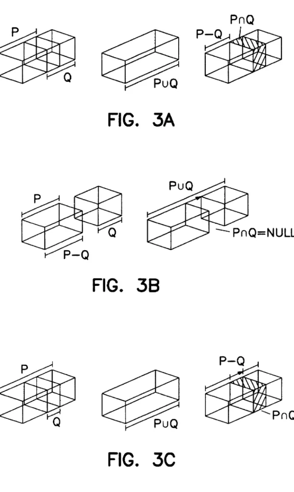
Boolean Operations on Dexel Models
Several Boolean operations. including union. intersection,
and difference, are de?ned for the dexel representation. The
union operation (0) either merges two intersecting dexels
together or constructs a linkbetween two separate dexels. as
illustrated in FIG. 3A. The intersection operation (u) forms
a dexel that belongs commonly to two dexels. or generates
null for no intersection (FIG. 3B). The difference operation
(—) removes the intersection portion from the dexel to be
subtracted (FIG. 3C). A newly generated dexel will inherit
properties from the original dexels that are involved in the
Boolean operation, i.e.. near_color. far_color, and type of a new dexel are determined by the dexel that creates it. For
example. in FIG. 3A, the new dexel P-Q will have a near color from P’s near color. a far_color from Q’ s near_color.
and type from P’s. It is generally not desirable to intersect
two dexels that have different material types because the
resulting material type is ambiguous. To solve this problem.
each material type is assigned a priority index. Thus the material type of the higher priority dexel is designated to the
new dexel.
An example of these Boolean operations is given in FIGS. 4A and 4B. In FIG. 4A, the inverted T-shaped solid is
constructed by using union operations between dexels of
two blocks. FIG. 4B shows the union of two di?erent types of objects and illustrates the result of a Boolean di?’erence
operation. The Boolean di?‘erence operation will be used
intensively for graphical NC milling simulation.
Graphical Display of Dexel Representation
The most e?icient display method for the dexel represen
tation is to align the dexel coordinate system with the screen
coordinate system. so that each grid point on the dexel plane
dexels to form a triangular mesh‘s'm. The triangular mesh
can also be converted into a boundary representation solid
modeling schemes. for example. the winged-edge data struc
ture“.
FIVE-AXIS NC SIMULATION AND VERIFICATION
Continuously performing Boolean di?’erence operations
between the moving tool and the workpiece setup (workpiece and ?xtures) simulates the operation of multi axis NC milling. Based on this simulation method, the present invention provides a discrete dexel NC veri?cation
method to exploit the respective advantages of normal vector intersection and spatial partitioning representation
approaches.
Five-Axis NC Milling Simulation
Simulation of the NC milling process is performed by
subtracting tool dexels from those of the workpiece setup.
The simulation algorithm and software of the invention ?rst
decomposes the tool path into a series of tool motions, then
discretizes each tool motion into several instances. Each
adjacent instance is separated by at most one unit along the x- or y-axis of the dexel coordinate system. The milling tool is placed at every instance sequentially and the shape of the
workpiece is updated by Boolean difference operations, as illustrated in FIG. 4(b).
The instances of motion approach approximates tool
swept volumes to dexel resolution. therefore. the result is
identical to the scan conversion model of the tool swept
volume. but the computational complexity is much lower.
Let the start and end CL points of a tool motion be denoted
by P and Q. respectively. and the unit tool axes by u and v. as shown in FIG. 6. Transforming the CL points and tool axes into the dexel coordinate system via Equation 2 yields
P’. Q'. u’. v'. respectively. The linear sweeping vectors of the
top and the bottom center points. denoted by s and t. are
given in the dexel coordinate system by.
(4) 30 35 45 50 55 65
i i
p.31-78, +05 Pad-7'- A‘, w ' J r w
dexel coordinate system. denoted by I". is given by,
(7)
+05 Pz+l s. n
where ?oor is a function which returns the largest integer value not greater than the given parameter. The x- and
y-component are rounded to address the nearest grid point,
the z-component remains a ?oating point depth value.
Applying this formula and the Boolean difference
operations, sequential images of a ?ve-axis NC milling
simulation may be generated. as shown. for example, in FIGS. 7. For three-axis milling simulations. the dexel rep
resentation of the cutting tool is only scan converted once and is translated to all instances of motiong. For ?ve-axis
milling simulations, however. the dexel representation of the
tool can not be transformed for different tool orientations. Therefore. the tool dexel representation is scan converted at
every instance of motion. which is more computationally intensive than three-axis milling simulation. However. the computation time can be reduced by checking if the tool axis
is ?xed during a motion. In this case the faster three-axis
simulation method can still be applied to the segment of
simulation.
An alternative method for tool motion representation is scan converting a ?ve-axis swept volume for each tool motion5 '17. However, since scan converting a swept volume
is much more computationally expensive. it is not preferred. Furthermore. since the dexel representation is limited by the
grid resolution, both methods will theoretically provide
identical results.
Discrete Dexel NC Veri?cation
Since the shape of a milled workpiece is characterized by the dexel representation. the central point. called the face point. of the front or back face of a dexel will lie on the
boundary of the workpiece, Although the dexel representa
tion of the workpiece is approximate. the face points which are generated during the scan conversion process and Bool ean operations lie exactly on the workpiece shell. The discrete dexel NC veri?cation algorithm and software of the invention exploits this fact and computes the deviation
between dexels and design surfaces during the simulation
process. Hence as the animated simulation process proceeds.
graphical results of dimensional veri?cation are presented
depicted in FIG. 8. Since design surfaces are not discretized.
several well known methods can be utilized to ?nd a surface
near-point based on the orthogonal propertym‘g. The
orthogonal property addresses that the minimum distance
between a space point P and a surface S(u.v) occurs when they are connected via the surface normal vector. The formulation utilized in this invention is a system of two
equations:
as. as, as. P.-s. (8)
‘a? “at” ‘3T 0
P - =
as. as, asz [ y S’
[0]
T T T PFS‘
and the solution is obtained by Newton’s method”. Since a surface is bounded in the parametric space. it is possible that
no solution can satisfy equation (8). In such cases, the minimum distance is measured between P and the nearest
boundary point. Also. there can be several surface points satisfying equation (8). so a preprocess is implemented that
isolates a sub-patch containing the global minimum. This
preprocess is based on the basic propenies of NURBS
surfaceszom.
A sample result of the veri?cation algorithm is demon strated in FIG. 9. In this ?gure. color-coded milling error information is displayed on the workpiece. which charac terizes the shape of the milled surfaces. The color map shown at the left-hand side of the ?gure depicts the range of milling error. The green color represents errors that are within a speci?ed tolerance, the upper eight colors represent the depth of undercut. and the lower represent overshoot.
The upper and lower bound of the color map is determined by a user speci?ed range. called the range of interest 1 (-0.05 to 0.05 in this case). Values of milling error that are
within the range of interest are displayed by corresponding colors. For overshoot deeper than the lower bound of the range of interest. the color depicting the deepest overshoot is used. For undercut larger the higher bound of the range of interest. the color of milling tool is displayed.
FIG. 10 demonstrates a set of sequential images of
simulation of a three-axis rough milling (3922 CL points)
and veri?cation of a ?ve-axis ?nish cutting (2155 CL points) on a NURBS surface. These images contain 640 by 400 grid points on the dexel plane and were displayed by using the image space display method. The performance is 14.5 and 3 instances per second for the three axis milling simulation
and the ?ve-axis veri?cation. respectively. The performance
of the algorithm depends on the material removal rate of
milling. or the amount of dexels to be updated. Hence the size of the CL-?le does not necessarily determine the length
of processing time. Intensive computation are required in the
?ve-axis simulation because scan conversion of tool dexel representation is performed at every instance of motion.
From the experiment results. the scan convm'sion of the ?ve-axis tool was the most time consuming part of the
20 25 30 35 45 50 55 60 65 results.
HARDWARE AND SOFTWARE IMPLEMENTATION
The hardware system of the present invention and a
software implementation of the discrete dexel NC milling
veri?cation algorithm of the present invention are illustrated
in FIGS. 11—14. As shown in FIG. 11. the system includes a workstation 10 (for example a Silicon Graphics Indigo/ Elan workstation with a UNIX operating system) including
a monitor 12. keyboard 14. mouse 16. black and white
printer 18. color printer 20. and printer/plotter 22. Housed in
chassis 24 are various other system components including the CPU and other supporting processors. mass storage for and RAM.
To create and/or modify designs of three dimensional
solid objects to be milled. the workstation 10 may be
programmed with CAD. solid or geometric modelling soft
ware (hereinafter referred to as “CAD software”) 30. as
illustrated in simpli?ed block diagram form in FIG. 12.
CAD software 30 includes routines and modules 32 for
creating and modifying design data representing a design
object (32A). and in particular an object to be NC milled in the case of the present invention. and for tool path genera
tion (328). and tool path veri?cation (32C). Software 32
receives input from the keyboard 14 and mouse 16 for this purpose. Software 32 can also import object design data from another source 34. such as a ?le developed on another system. Software 32. operating on the workstation. produces design data 36 (for example in a NURBS format). which can be rendered graphically by software routines and modules 38. which produce CRT or printed output 40 and 42 respec
tively.
Referring now to FIG. 13. there is illustrated in simpli?ed flow chart form the process and software 32C of the present
invention for verifying NC milling tool paths. Data for the workpiece. ?xture. cutting tool and tool path are provided
(52). The dexel representations for the workpiece and ?xture are determined (54). The tool path is decomposed (56) into
a plurality of tool motions. and each tool motion is dis
cretized into a plurality of instances in time. The position of the workpiece at a given instance in time is simulated (58) given the tool motion data. and the solid model of the cutting
tool at the corresponding position is converted to a corre
sponding dexel representation (60). Boolean operations are
then performed to subtract the tool dexels from the workpiece. so that the shape of the workpiece is simulated (62). The distance from the updated dexels to the design
surfaces are then calculated (63). The graphical representa
tion of the simulated workpiece is then updated based on the
newly determined workpiece dexel representation (64). ‘This
output can be done as an animation sequence. or as still
frames. A check is made to determine if all positions of the
is applicable to other partitioning schemes as well.
REFERENCES
1) Oliver. J. H. and Goodman. E. D.. “Direct Dimensional NC Veri?cation." Computer Aided Design. Vol. 22, No.
l. 1990. pp. 3-10.
2) Sungurtekin. U. A. and Voelcker. H. B.. “Graphical
Simulation & Automatic Veri?cation of NC Machining Programs." Proc. 1986 IEEE International Conference of Robotics and Automation. April 1986. pp. 156-165. 3) Voelcker. H. B. and Hunt. W. A.. "The Role of Solid
Modeling in Machine-Process Modelling and NC
Veri?cation.” SAE Technical Paper No 810195. Feb
ruary 1981.
4) Ho?imann. C. M.. Geometric and Solid Modeling. An
Introduction. 1989. Morgan Kaufmann Publishers. Inc..
San Mateo. Calif.
5) Narvikar. A.. Huang. Y. and Oliver. J. H.. “Intersection
of Rays with Parametric Envelope Surfaces Represent ing Five-Axis NC Milling Tool Swept Volumes." Proc.
ASME Advances in Design Automation 1992. V012. D. A. Hoeltzel. ed.. pp. 223-230.
6) Jerard, R. B.. Hussaini. S. Z.. Drysdale. R. L.. and Schaudt. B.. “Approximate Methods for Simulation and Veri?cation of Numerically Controlled Machining
Programs.” The Visual Computer. 1989. pp. 329-348.
7) Chang K. Y. and Goodman E. D.. “A Method for NC
Tool Path Interference Detection for A Multi-Axis
Milling System." ASME Control of Manufacturing
Process. DSC-Vol. 28/PED-Vol. 52. 1991. pp. 23-30.
8) Oliver. J . H.. “E?icient Intersection of Surface Normals
With Milling Tool Swept Volumes for Discrete Three Axis NC Veri?cation.” Journal of Mechanical Design.
June 1992, Vol. 114. pp. 283-287.
9) van Hook. T.. “Real-Time Shaded NC Milling
Display." Computer Graphics. (Proc. SIGGRAPH ’86).
Volume 20. Number 4. August. 1986. pp. 15-20. 10) Menon. J. P. and Robinson. D. M.. “High Performance
NC Veri?cation via Massively Parallel Raycasting:
Extension to New Phenomena and Geometric
Domains.” PED-Vol. 59. Concurrent Engineering. ASME 1992. pp. 179-194.
11) Saito. T. and Takahashi. T.. “NC Machining with G-bu?er Method.” Computer Graphics. Proc. SIG
GRAPH ’91. Volume 25. Number 4. July. 1991. pp. 207-216. 20 25 35 45 55 65
17) Wang. W. P.. and Wang. K. K.. “Geometric Modeling for Swept Volume of Moving Solids.” IEEE Computer Graphics and Applications. December. 1986. pp. 8-17. 18) Pegna. J. and Wolter. F.-E.. “Designing and Mapping Trimming Curves on Surfaces Using Orthogonal
Projection.” Proc. ASME Advances in Design
Automation. Vol. 1. Computer Aided and Computa tional Design. DE-Vol. 23-1. September. 1009. pp.
235-245.
19) Barnhill. R. E. and Kersey. S. N., “A Marching Method for Parametric Surface/Sm'face Intersection.”
Computer Aided Geometric Design. No. 7. 1990. pp.
257-280.
20) Piegl. L.. “Curve and Surface Constructions Using
Rational B-Splines.” Computer-Aided Design. Vol. 19.
No. 9. November 1987. pp. 485-498.
21) Piegl. L.. “On NURBS: A Survey.” IEEE Computer Graphics and Applications. January. 1991. pp. 55-71. 22) Kincaid. D. and Cheney. W.. Numerical Analysis. Mathematics of Scienti?c Computing. Brooks/Cole
Publishing Company. 1991. CA.
23) Leighton. F. T.. Introduction to Parallel Algorithm and Architectures: Arrays. Trees. Hypereubes. M. Kauf
mann Publishers. 1992. CA.
24) Baron. R. J. and Higbie. L.. Computer Architecture.
1992. Addison Wesley Publishing Company. New
York.
What is claimed is:
1. A method for visualization of a ?ve-axis NC milling process simulation to determine the ability of a NC milling
operation to produce a desired design surface of a designed
object, said method using a computer having an output
display device. comprising the steps of:
(a) providing the computer with data representing a solid
object representation of a workpiece. a cutting tool. and a surface of the designed object;
(b) converting. using the computer. the data to provide a dexel representation of the workpiece. the dexel rep resentation of the workpiece comprising a plurality of
workpiece dexels;
(0) providing the computer with ?ve-axis tool path data
representative of a tool path to be used in milling the
workpiece with the cutting tool;
((1) decomposing the tool path into a series of tool motions and discretizing each tool motion into a plurality of
discrete positions. wherein the tool motions are repre
(g) using the computer to determine the distance between
one or more of the updated workpiece dexels and the
design surface. the distance determined by ?nding a
point on the design surface near a dexel for which the
distance to the design surface is being determined; and
(h) repeating steps (e). (f) and (g) to process a plurality of successive cutting tool positions; and
(i) using the computer and the distances determined in step (g). generating. on the output display device. a graphical display in at least two dimensions of the di?erence between the desired design surface and the
simulated shape of the workpiece.
2. A method according to claim 1 further including the
step of generating and updating the graphical display sub
stantially simultaneously with the determining of the dis
tances in step (g) to simulate the removal of material from the workpiece as the cutting tool moves along a cutting tool
th.
p83. A method according to claim 1. further including the
step of color-coding the difference between the desired design surface and the simulated shape.
4. A method according to claim 1. further including the step of generating on the output device a graphical display of the difference between the simulated shape and the design surface as an animated sequence.
5. A method according to claim 1 further wherein the step
(g) of determining the distance includes the step of using an
orthogonal property to ?nd a point on the design surface near the dexel for which the distance to the design surface is
being determined.
6. A method according to claim 5 further including the step of using the computer to preprocess the design surface
to ?nd a sub-patch of the design surface to look for the
nearest point on.
7. A method for visualization of a NC milling process
simulation to determine the ability of a NC milling operation to produce a desired design surface of a designed object. said
method using a computer having an output display device. comprising the steps of:
(a) providing the computer with data representing a solid
object representation of a workpiece and a cutting tool. and a surface of the designed object;
(b) converting. using the computer. the data to provide a
spatial-partitioned representation of the workpiece, the
spatial-partitioned representation of the workpiece
comprising a plurality of workpiece subregions each
de?ned by a corresponding data set;
(0) providing the computer with tool path data represen
tative of a tool path to be used in milling the workpiece
with the cutting tool;
((1) using the tool path data. simulating on the computer
the positions of the cutting tool relative to the work piece and converting the solid model data of the cutting tool to a corresponding spatial-partitioned representa tion of the cutting tool positions wherein the spatial
partitioned representation comprises a plurality of cut ting tool subregion each de?ned by a corresponding
data set; 20 25 35 45 50 65
display in at least two dimensions of the difference
between the desired design surface and the simulated
shape of the workpiece.
8. A method according to claim 7 wherein said subregions of said workpiece and said cutting tool positions are de?ned
as dexels.
9. A method according to claim 7 further wherein step (d)
includes the steps of:
(i) decomposing the tool path into a series of tool motions and discretizing each tool motion into a plurality of
discrete positions. wherein the tool motions are repre
sented by tool motion data; and
(ii) using the tool motion data. simulating on the computer
the position of the cutting tool relative to the workpiece at a particular position. and for that position converting
the solid model data of the cutting tool to a correspond
ing spatial-partitioned representation of the cutting tool
comprising a plurality of cutting tool subregions each
de?ned by a corresponding data set; and
further wherein the steps (e) and (f) are performed sequen
tially for each of the discretized instances in time so that a
plurality of successive cutting tool positions occurring at
ditTerent instances in time are processed in sequence. 10. A method according to claim 7 further including the
step of generating and updating the graphical display sub
stantially simultaneously with the determining of the dis
tances in step (t) to simulate the removal of material from
the workpiece as the cutting tool moves along a cutting tool
path.
11. A method according to claim 7. further including the step of color-coding the di?erence between the desired design surface and the simulated shape.
12. A method according to claim 7, further including the step of generating on the output device a graphical display of the dilference between the simulated shape and the design surface as an animated sequence.
13. A method according to claim 7 further wherein the
step (t) of determining the distance includes the step of using
an orthogonal property to ?nd a point on the design surface near the subregion for which the distance to the design
surface is being determined.
14. A method according to claim 7 further including the step of using the computer to preprocess the design surface
to find a sub-patch of the design surface to look for the nearest point on.
15. Apparatus for visualization of NC milling process simulation to determine the ability of a NC milling operation to produce a desired design surface of a designed object,
comprising:
(a) means for storing data representing a solid object
representation of a workpiece and a cutting tool. and a
surface of the designed object. and for storing tool path
data representative of a tool path to be used in milling
the workpiece with the cutting tool;
(b) means for converting the data to provide a spatial
updated workpiece subregions and the design surface.
the distance determined by ?nding a point on the design
surface near the subregion for which the distance to the
design surface is being determined;
(f) an output display device; and
(g) means using the determined distances for generating. on the output display device. a graphical display in at
least two dimensions of the diiference between the
desired design surface and the simulated shape of the
workpiece.
16. The apparatus of claim 15 further wherein subregions of said workpiece and said cutting tool positions are de?ned
as dexels.
17. The apparatus of claim 15 further wherein the means
for determining the distance between the updated workpiece
subregions and the design surface includes means for using
an orthogonal property to ?nd a point on the design surface near the subregion for which the distance to the design
surface is being determined.
18. The apparatus of claim 17 further including means for
preprocessing the design surface to ?nd a sub-patch of the
design surface to look for the nearest point on.
19. A method for designing and manufacturing an object
using NC milling. comprising the steps of:
(a) creating a design for the object on a computer-aided
design system to produce a designed object;
(b) using a computer, generating NC milling path data
designed to cut a workpiece to provide at least one
surface of the designed object;
(c) using milling process simulation to determine the ability of a NC milling operation to produce the desired design surface. said process using a computer having an output device. comprising the steps of:
(1) providing the computer with data representing a
solid object representation of a workpiece and a
cutting tool. and a surface of the designed object; (2) converting. using the computer. the data to provide
a spatial-partitioned representation of the workpiece. the spatial-partitioned representation of the work
piece comprising a plurality of workpiece subregions
each de?ned by a corresponding data set;
(3) providing the computer with the tool path data
representative of a tool path to be used in milling the
workpiece with the cutting tool;
(4) using the tool path data. simulating on the computer
the positions of the cutting tool relative to the workpiece and converting the solid model data of the cutting tool to a corresponding spatial-partitioned
2 30 35 45 55 65
the NC milling tool path data to improve the milling of
the workpiece to obtain the desired design surface; and
(e) milling a workpiece using the adjusted tool path data
to produce the desire surface of the designed object. 20. A computer-aided-design system for designing an object and creating NC milling tool path data for milling at least one surface of the designed object. comprising:
(a) computer-aided-design means for designing the object
including input means for receiving design instructions
from a user and means for displaying the designed object to the user. the computer-aided-design means producing data representative of at least a surface of the
designed object;
(b) means for generating NC milling tool path data based
on the data representative of the designed object. the
tool path data representative of a tool path to be used in
milling the workpiece with the cutting tool;
(c) means for storing data representing a solid object representation of a workpiece and a cutting tool. and the surface of the designed object. and for storing the
tool path data;
(d) means for converting the data to provide a spatial
partitioned representation of the workpiece. the spatial
partitioned representation of the workpiece comprising
a plurality of workpiece subregions each de?ned by a corresponding data set;
(e) means using the tool path data for simulating the positions of the cutting tool relative to the workpiece and converting the solid model data of the cutting tool to a corresponding spatial-partitioned representation of
the cutting tool positions wherein the spatial partitioned representation comprises a plurality of cut ting tool subregions each de?ned by a corresponding
data set;
(i) means using the cutting tool subregions for determin ing a simulated shape of the workpiece by performing Boolean difference operations between the workpiece
subregions and the cutting tool subregions to produce a
set of updated workpiece subregions comprising those workpiece subregions that intersected with the cutting
tool subregions; and
(g) means for determining the distance between the
updated workpiece subregions and the design surface.
the distance determined by ?nding a point on the design
surface near the subregion for which the distance to the
design surface is being determined.