International Journal of Innovative Technology and Exploring Engineering (IJITEE) ISSN: 2278-3075, Volume-8 Issue-8S2, June 2019
Abstract Background/Objectives: The fourth industrial revolution represents the transition to an intelligent society that combines sensor, network, and artificial intelligence to significantly improve human life. Recently emerged drones are replacing manned airplanes, which are expensive to maintain, and are used in a variety of fields such as shooting, shipping, and surveillance.
Methods/Statistical analysis: Drones are required to perform the duties based on accurate location. Therefore, it is required to identify an exact location. However, drones are using a position sensor, GPS, but still suffering from errors including the location of satellite, transmission error, and internally installed clock in the satellite causing an error with several meters. In this study, image process-based drone landing techniques are researched for correcting the location of drone in the use of drone camera that is used to supplement GPS.
Findings: In this study, camera was connected to Raspberry Pi that was used as a drone controller to record while analyzing photos recorded in a certain period of time to supplement the error in GPS estimates to find target point. Suggested drone landing technique is programmed to find an exact landing area by determining the moving direction of drones towards the wind measured with position sensor in flight controller and the direction of wind estimated with image if there was influence of wind. Due to various changes in environment in daily lives, experiment was conducted in Gazebo simulator of a drone.
Improvements/Applications: It was confirmed that drones were able to access to the error within 1.5m from pre-determined landing area in spite of the influence of wind.
Keywords: Autonomous flying drones ,ROS, Image Processing, OpenCV, Wind
I. INTRODUCTION
The fourth industrial revolution represents the transition to an intelligent society that combines sensor, network, and artificial intelligence to significantly improve human life. Recently emerged drones are flying objects that are designed to perform the assigned mission without a pilot. Drones are replacing manned airplanes, which are expensive to maintain, and are used in a variety of fields such as shooting, shipping, and surveillance. Drones have recently been used
Revised Manuscript Received on May 22, 2019.
Young-Kwan Ju, Department of Computer Science, Chungbuk National University, Republic of Korea
Hyung-Jin Mun, Dept. of Information & Communication Engineering, Sungkyul University, 14097, Anyang-city, Republic of Korea
Kun-Hee Han, Dept. of Information Communication & Engineering, Baekseok University, 31065, Cheonan-city, Republic of Korea
in a variety of commercial applications such as telecommunications, aerial photography, and shipping, starting with Amazon's shipping service. These drones use GPS to fly to specific destinations because they must travel to a defined destination via flight [1-4].
In general, GPS position measurement is subject to errors due to structurally generated satellite time error, satellite position error, ionospheric and convective refraction, and multipath. Therefore, the GPS attached to the drones has errors with several meters, and various studies have been conducted to reduce the error for accurate flight of the drones [1-3,5]. The flight of the drones makes them land at a distance of several meters from the target point due to the error of this GPS that user find it inconvenient for having to find the corresponding drones. In addition, the use of drones is expanding in various fields, and it is required to conduct a research to improve the accuracy of drones' flight.
In this paper, the drone's landing control method was studied using image processing technique so that the drone can land closer to the target point. As for the organization of this study, related researches are presented in Chapter 2, and the algorithm is proposed in Chapter 3. In Section 4, the proposed algorithm is experimented, and conclusion is drawn in Section 5.
II. RELATEDWORK
For the accurate flight of the drones, a combination of drones' flight design, flight control technology, position-based navigation technology, and various sensor technologies are used. The drones 'displacement control technology maintains the body of drones in an optimal condition for flight, and serves a role of converting the control signal to a command transmitted by the user. Playing the role of operating system, ROS (Robot Operation System) is recently used for flight control and efficient control of peripheral sensors. The low-priced and high-performance hardware that implements the operating system is adopted, and Raspberry Pie has recently been utilized.
2.1. ROS
ROS (Robot Operating System) is an open source meta-operating system for robots. ROS provides hardware abstraction, low-level device control and frequently used functions provided by
general operating systems, and transfers message
Image Processing Based Drone Landing
Technique Considering GPS error and wind
Direction
between processes and package management functions. The ROS also provides tools and libraries for securing, building, writing, and executing code that works across multiple computer systems. ROS is applied to automobiles, ships, airplanes, and robots. This ROS provides a development integration environment, a development library, and a debugging tool necessary for development of sub-device driver, communication protocol, hardware resource management, communication between processes, and package management necessary for controlling hardware constituting robot [4,6-10] .
2.2.Pixhawk and Raspberry Pi
Pixhawk is an open source based flight control controller. The Pixhawk controller performs attitude control and position control of the drone. The position control adjusts the position of the drone to move to the target position and adjusts the force and intensity of the motor so that the attitude control can change to the desired attitude. Pixhawk originally used the Atmega328 CPU, but STMicro's ARM Cortex-M4 was used from a second-generation controller. As of now, Quarkcom's Snapdragon chip is used[10,12].
Raspberry Pi is a credit card sized single board computer developed by the Raspberry Pi Foundation in England to promote the education of basic computer science in developing countries. Raspberry Pie is used as a computer for robot control, IOT control, automobile, and drone while adopting quad core ARM Cortex-A7 CPU and 1GB RAM .Raspberry Pi is popular as a control computer due to its low price, and is also used for control of drones. Raspberry Pi uses the aforementioned ROS and Mavros, a communication package of ROS. MAVLink communication protocol supported by the Mavros package is used sending commands to and from the flight controller [11].
2.3.Image tracking
Image tracking is an important technique for finding a pattern of an image set by a user in a photographed image or by searching for a specific image set by using OpenCV (Open Computer Vision) image processing. Image processing extracts important feature features a photograph or an image and matches them when recognizing a substance to be searched in a photograph or an image. There are several techniques for image matching, but it refers to the Scale Invariant Feature Transform (SIFT) technique used in FindObject2D of ROS. SIFT also extracts feature points and compares them as well. In order to solve the problem that is sensitive to the scale change of the existing image, the SIFT technique finds a large value from vertex on the scale axis in the image based on the DoG (Difference of Gaussian). In ROS image tracking, OpenCV library is used to perform real-time image tracking. The library package used is FindObject2D [7].
III. AUTONOMOUSFLYINGDRONESAVAILABLE
TOACCURATELYLAND
Drones are recently equipped with four propellers and also with a flight controller, GPS, and camera for basic safe flight
for operation. Therefore, it is assumed in this study that the drones are quadrotor equipped with four propellers, a flight controller, GPS and camera where drones are in a situation for having to land near the target within about 10m via a satellite navigation system.
3.1. Land exploring technique in the use of image process
Suggested drone control algorithm is to prevent drones from deviating the landing area due to the influence of wind when drones land. Low-priced drone provides a function for taking a photo by using attached camera during the flight and also for operating a drone with manipulation of users. Such low-priced drones providing aforementioned functions are internally installed with terrestrial magnetic sensor, position sensor, and camera.
Drones' flight is subdivided into three stages. First of all, the flight of drones is divided into a take-off process, a flight process in the air, and a landing process from the air to the ground. The most difficult course in the three courses is the landing process. The landing process is often due to disturbance in the process of landing on the ground, making it impossible to land at the desired landing point.
[image:2.595.320.495.454.573.2] [image:2.595.312.547.624.831.2]In the process of moving to the target point using GPS and landing with it, an error with several meters occurs due to low-cost GPS. In order to solve this problem, [5] has been proposed to capture the images using the camera built in the drone and to reduce the error between the target point and the landing point.
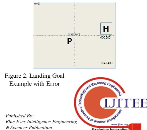
[Figure 1] indicates the vertical landing position of the ground when the drones move by the GPS and arrive at the correct landing point. It is assumed that the resolution of the drone camera is 640 * 480.
Figure 1. Land Goal Example
[Figure 2] represents a photograph where the target point is located on the upper right side when it is moved by GPS but is recorded vertically due to an error.
International Journal of Innovative Technology and Exploring Engineering (IJITEE) ISSN: 2278-3075, Volume-8 Issue-8S2, June 2019
3.2. Landing exploring technique in the use of improved image process considering wind speed
The disturbance that makes it difficult to fly the drones varies in rain, wind, and snow. However, rain and snow were not considered in this study because they are the main causes for preventing most of the drones from flying. However, the wind directly affects the drones' landing. Therefore, the safe landing is researched in this study by considering the wind.
When the drones arrive at the target point, they land according to landing command.
[image:3.595.48.271.393.693.2] [image:3.595.48.267.402.549.2] [image:3.595.319.553.536.702.2]It is assumed that this process is applied when going down to the ground at the altitude of 10m[Figure 3].represents when the drone took a picture at an altitude of 10m above the ground. Point P is where the drones land on the ground as they are supposed to, and H is the target point. It is intended to correct the position of the drone so that the PH landing is within 1.5m.
[Figure 3] indicates the coordinates plane based on the point P with the drone rotated in the normal direction. The range that can be taken depends on the resolution of this camera. In this study, an algorithm was made on the
assumption that a rectangular area was
photographed at an altitude of 10m above the ground. In this case, the distance of the PE is always equal to the distance between the drones and the ground.
Point P can be easily found at point H when drawing the xy- plane as the origin.
Figure 3. Position of a drone and actual distance of target point and landing area.
Figure 4. Screen for taking a photo of target point and arriving area seen from a drone
[Figure 4] represents the target point (P) and landing point (H) on the screen shot by the drones.
The photographed image is 640X480, and the position of the pixel at the point P is 320X240 based on the point O.
Assuming that the position of the pixel at point H is from point O to the right by and the pixel at the bottom is b pixel, the position of point H with respect to point P can be obtained by using (formula 1).
𝑥0= 𝑎 − 320
𝑦0= 240 − 𝑏 (1)
The distance of the actual PH can be estimated using the distance of the PE.
H is determined based on P, and the actual distance of PH
on the ground is as follows (formula 2).
𝑃𝐻 = 𝑃𝐸 ×
𝑥0 320
2
+ 𝑦0
320 2
(2)
[Figure 5] represents the process of reducing the error between the current location and the landing area after the drones move to the target location using GPS.
After moving the position information of the drone to the target point, the front part of the drone rotates in the north direction. At the same time, the distance between the drone landing position and the target point is measured after photographing the current position.
Using the (formula 2), distance is calculated. If it turns out to be greater than 1.5m, drones need to move to the left or right by , and to the top or bottom by . After
taking a photo, distance to the targeted area is calculated along with the location of drones.
After repeating until the distance is less than 1.5m, drones arrive on the ground if the distance turns out to be less than 1.5m.
Even if operating drones in the intensity of wind less than 10m/sec, there must be an influence of wind. In this study, algorithm for moving drones in consideration of the direction of wind is suggested even though the intensity of wind is less than 10m/sec.
Figure 5. Landing algorithm of drone at a target point
Direction and intensity of wind can be expressed in vector. In other words, if assuming
calculated to be , and the intensity can be
calculated to be . As shown in the [Figure 6], moving direction of drones can be calculated with the difference between moving vector and wind vector. In other words, w indicates a wind blowing to north-west direction, and u indicates a movement direction of drones. In order to move to the destination, H, it is required to consider the direction of wind while moving to the direction, v, in red, and the scale. In other words, the direction and scale of drones can be calculated as follows(formula 3).
𝑣 =𝑢−𝑤 = 𝑥
0
,𝑦
0
− 𝑠,𝑡 = 𝑥
0
−𝑠,𝑦
0
−𝑡 , 𝑢 = 𝑥
0,
,𝑦
0
,𝑤 = 𝑠,𝑡
(3)Figure 6. Difference between drone moving vectors and wind vectors
IV. IMPLEMENTATIONANDEXPERIMENT
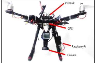
[image:4.595.47.287.198.355.2]The proposed algorithm is composed of a raspberry chip board and hardware using Pixhawk that is attached to the drones. The software installed the PX4 firmware on the Drones flight controller, Pixhawk, and built the ROS environment on the Raspberry Pivot board in conjunction with the flight controller. The drones were used to take a picture of the landing area at the time of landing and to actually land while constantly correcting the position in the taken picture.
Figure 7. Hardware configuration of drones
[Figure 7] represents the drones used in the experiment, and the drones have Pixhawk located in the center of the motor. The Raspberry Pi was installed on one side of the bridge connected to the body of the drones, and the camera used to take a photo of the landing area was fixed to the anchored band of the battery in the center of the drones facing downward.
The drone software measures the degree of movement based on the influence of the wind according to the position sensor (GPS) and moves to the position of the landing point while comparing the measured displacement and the photo information of the drones. Software development has installed ROS Kinetic version in Raspberry Pi and experimented by confirming the required steps such as sensor operation, camera initialization, image processing and so on from the operation of the drones flight controller.
In this experiment, the drones were set to off-mode and to land autonomously at an altitude of 10m. The drones' flight controllers have a user-controlled mode and an off-board mode that the drone performs an autonomous flight. In order to test the drones' landing process, an off-mode was setup where users did not intervene.
In the off mode, the Raspberry Pi adjusts the drones and generates a control signal to the Pixhawk based on the displacement of the position sensor and the camera image to proceed the landing.
The landing process begins when the drones arrive at the landing location. When the drones arrive at the landing point, Raspberry Pi receives the displacement value of the Pixhawk position and records the photo shoot. After confirming whether the coordinates of the drones are in the range of the landing position, and, if it is in the landing range, the next procedure is to calculate the direction of the wind and take a picture of the landing point followed by initializing the process for landing.
The position sensor displacement of the drones compensates the direction of the drones by calculating the displacements of the x and y axes in one second followed by calculating the displacement of the direction of the picture for one second to the drone camera's landing point.
[image:4.595.57.242.536.659.2]International Journal of Innovative Technology and Exploring Engineering (IJITEE) ISSN: 2278-3075, Volume-8 Issue-8S2, June 2019
Figure 8. Drones Action Package Raspberry pie is to match the photos on the landing point
and provide moving direction of Pixhawk. Camera in the drone uses displacement of objects in the landing area as well as the difference of time in the photo shooting for the influence of wind to calculate the displacement for movement. Raspberry pie of drones shall issue the calculated displacement of movement for Pixhawk to use by utilizing the photos in the camera. Operating controller of the drone receives the location of movement issued by Raspberry and
moves by the displacement.
Raspberry pie designates a certain object in the middle of a photo representing the landing point of find_object_2d to detect objects on the landing area. Object-detected issues x and y displacements of detected objects comparing them with the location displacement of drones and controlling the location of drones. Drone controller, Pixhawk is connected with the relationship of issuance and subscription among various nodes indicated on the [Figure 9].
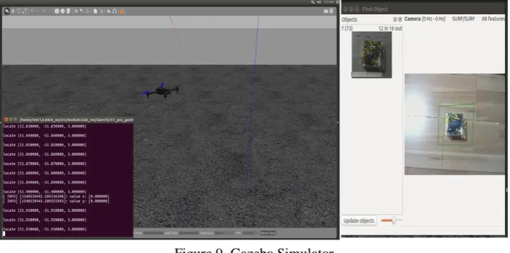
Figure 9. Gazebo Simulator Drones are modified to land according to the influence of
wind and displacement in Gazebo simulator. Wind influence was entered by randomly causing x and y displacements, and actual USB camera was used to recognize the photo by recording the landing area.
[Figure9] represents an implementation of the gazebo simulator, the landing point recognition program, and the object tracking function of the drones. When specifying an object in find_object_2d on the right side of the picture, a rectangle appears around the object on the screen. Finding an object designated as a landing point, a program called objects_detected runs in the background and issues the center of the object x and y. At the bottom left, a code for a drone flight operates subscribing x and y of the published object and printing them together with the current position of the drones.
[Figure9] shows the experiment of the landing drones on the simulator with the Gazebo simulator. In the Gazebo simulation, the drone was confirmed to recognize the landing position and calibrate and land considering the randomly
generated motion. If the object does not exceed a certain threshold of wind displacement and photo displacement within the image, the drones land vertically along the landing point.
[image:5.595.124.483.349.527.2]…
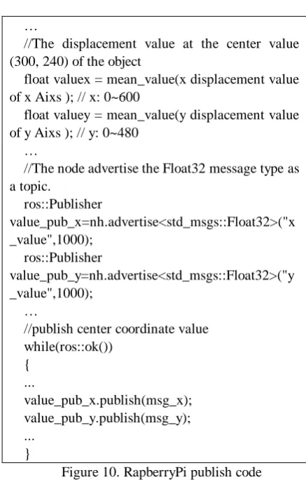
//The displacement value at the center value (300, 240) of the object
float valuex = mean_value(x displacement value of x Aixs ); // x: 0~600
float valuey = mean_value(y displacement value of y Aixs ); // y: 0~480
…
//The node advertise the Float32 message type as a topic.
ros::Publisher
value_pub_x=nh.advertise<std_msgs::Float32>("x _value",1000);
ros::Publisher
value_pub_y=nh.advertise<std_msgs::Float32>("y _value",1000);
…
//publish center coordinate value while(ros::ok())
{ ...
value_pub_x.publish(msg_x); value_pub_y.publish(msg_y); ...
[image:6.595.58.277.39.383.2]}
Figure 10. RapberryPi publish code
When the center of the landing point is found in 'objects_detected,' a rectangle representing the object of the right side of Gazebo is displayed around the object. The average of the center points of these squares is accumulated for one second to calculate an average of them. The center value is issued after issuance code of the object position at the end of the code[Figure 11] is calculated. The issued value is received and used by the subscriber.
…
//Callback function void
valueCallback_x(conststd_msgs::Float32::ConstPtr&msg )
{
ROS_INFO("value x: [%f]", msg->data); xv = msg->data;
} void
valueCallback_y(conststd_msgs::Float32::ConstPtr&msg )
{
ROS_INFO("value y: [%f]", msg->data); yv = msg->data;
}
// display of current position displacement value of a drone
// pose.position : current position value of a drone float dr_x = mean_value(pose.position.y ); // x: 0~600 float dr_y = mean_value(pose.position.y); // y: 0~480 …
//Subscribe central coordinates notified in the topics
ros::Subscriber sub1 = nh.subscribe("x_value", 1000, valueCallback_x);
ros::Subscriber sub2 = nh.subscribe("y_value", 1000, valueCallback_y);
…
float diff_x = mean(dr_x– xv); //average value for 1 second
float diff_y = mean(dr_y– yv); //average value for 1 second
//Move drones according to central coordinates if( diff_x>thres_x )
{
pose.pose.position.x = diff_x; }
if( diff_y>thres_y ) {
pose.pose.position.y = diff_y; }
...
Figure 11. Pixhawk subscribe code
This code receives the center value of an object and lands on it by moving the center by increasing or decreasing the drone position. When Raspberry Pie issues a displacement value obtained by taking a picture, Pixhawk subscribes to it and bring out the callback function to receive the x coordinate movement of the drones in the same way as above, and calculates the displacements and differences of the drones for one second. Afterwards, the position of the drones is set by entering the calculated displacement into pose.x and pose.y. In the gazebo simulator, the code in [Figure 11] moves the drones according to the recognized object position in the image, and if the object is located at the center of the drone image, the drone can land vertically.
V.CONCLUSION
The algorithm proposed in this study turns out to be much influential on the landing of drones, and allow the drones to land closer to the target position set by the user by using a robust image processing technique.
In order to verify the proposed drone landing technique, we have experimented with the drones virtual simulator, Gazebo. The drones on the Gazebo was experimented to see if it moved to the target point according to the image set in the input image. The drone changed the position of according to the degree of matching of the target position in the image. When the drone placed the target in the center of the image, it recognized how the captured image arrived at the target object position and stopped the operation. Through this experiment, it was confirmed to be difficult to land at the landing point correctly due
[image:6.595.299.545.41.321.2]International Journal of Innovative Technology and Exploring Engineering (IJITEE) ISSN: 2278-3075, Volume-8 Issue-8S2, June 2019
land close with an error of about 1.5m.
It was experimented with the pixhawk of a drone, a flight controller, and drones with Raspberry Pie 3 that performed image processing and flight control.
In the future research, it is necessary to study the landing point by reading the photograph taken by the drone even if the landing point is not displayed, and to reduce the error by correcting the resolution of the photographing.
REFERENCES
1. Hyung-Jin Mun, Hee-Young Jeong, Kun-Hee Han. Improved Trilateration Method on USN for reducing the Error of a Moving Node Position Measurement. Journal of Digital Convergence.2016;14(5): 301-307. 2. GyeongHyeon Cha, Isaac Sim, SeungGwan Hong, Jun Hee Jung, Jin
Young Kim. A Study of Method and Algorithm for Stable Flight of Drone. Journal of Satellite, Information and Communications.2015; 10(3): 32-37. 3. Chansik Park. An Error Analysis of GPS Positioning. Journal of Institute of
Control, Robotics and Systems. 2001; 7(6): 550-557.
4. Upton, E., Halfacree, G. Raspberry Pi user guide. John Wiley & Sons; 2014.
5. Hyeon-Sik Kim, YoungkwanJu, Joong-Nam Jeon. Autonomous flying drones capable of accurate landing through image matching. Computer and Information Communication. 2018; 26(1):33-37.Available from : http://ricic.chungbuk.ac.kr/ricic/journal
6. Gazebo [internet]. Available from : http://wiki.ros.org/Gazebo
7. IntRoLab [internet]. Available from : https://github.com/introlab/find-object
8. Jaeyoung-Lim. modudculab_ros [internet]. Available from : https://github.com/Jaeyoung-Lim/modudculab_ros
9. Mavros [internet]. Available from : http://wiki.ros.org/mavros
10.Meier, L., Tanskanen, P., Heng, L., Lee, G. H., Fraundorfer, F., Pollefeys, M. PIXHAWK: A micro aerial vehicle design for autonomous flight using onboard computer vision. Autonomous Robots. 2012; 33(1-2): 21-39. 11.ROS.org | Powering the world’s robots [Internet]. Available from :
http://www.ros.org/