OPEN LOOP AND CLOSED LOOP PERFORMANCE
OF SRM DRIVE WITH A NEW CONVERTER
TOPOLOGY
S. Vishnu Vardhan
1, Mrs. M. Kedareswari
21
P.G Student, Department of EEE, Mahatma Gandhi Institute of Technology,
Gandipet, Telangana, (India)
2
Assistant Professor, Department of EEE, Mahatma Gandhi Institute of Technology,
Gandipet, Telangana, (India)
ABSTRACT
Switched Reluctance Motor (SRM) has become a competitive selection for many applications of electric
machine drive systems recently due to its relative simple construction and its robustness. It not only features a
salient stator with concentrated coils, which allows earlier winding and shorter end returns than other types of
motors, but also features a salient pole rotor, which has no conductors or magnets and is thus the simplest of all
electric machines. In this paper, the design of new converter, consisting of Half-bridge IGBT modules and SCRs
for open loop and closed loop control of switched reluctance motor drives are proposed. The proposed
converter topology is the variation of asymmetric bridge converter. In order to verify the proposed converter
topology for SRM drives, it is verified through open loop and closed loop control through MATLAB/SIMULINK
environment.
Keywords: Switched Reluctance Motor Drives, Asymmetric Bridge Converter, Converter Topology.
I. INTRODUCTION
The Switched Reluctance Motor (SRM) drives have recently gained considerable attention among researchers
due to several reasons. In construction, the SRM is simplest of all electric machines. Only the stator has
windings. The rotor contains no conductors or permanent magnets. It consists simply of steel laminations
stacked onto a shaft. It is because of this simple mechanical construction that SRMS carry the promise of low
cost, which in turn has motivated a large amount of research on SRMs in the last decade. The mechanical
simplicity of the device, however, comes with some limitations. Like the brushless DC motor, SRMs cannot run
directly from a DC bus or an AC line, but must always be electronically commutated. Also the saliency of the
stator and rotor is necessary for the machine to produce reluctance torque, causes strong non-linear magnetic
characteristics, complicating the analysis and control of the SRM. Not surprisingly, industry acceptance of
SRMs has been slow. This is due to combination of perceived difficulties with the SRM, the lack of
commercially available electronics with which to operate them, and the entrenchment of traditional AC and DC
machines in the market place.
Fig.1 shows the cross section of an 8/6 pole four phase basic switched reluctance motor. It has been realized [1],
that the reluctance motor requires only unipolar or unidirectional currents and this gives rise to the possibility of
operating with only one switching device in series per phase, instead of two in series in each phase leg of an AC
Fig.1: Basic Switched Reluctance Motor
True reluctance machine in the sense that both rotor and stator have variable reluctance magnetic circuits, or,
more properly, it is a double salient machine. The concept of switched reluctance machine is very old, going
back to the 19th century inventions called “electromagnetic engines” [3], which were the forerunners of modern
stepper motors. The switched reluctance motor is basically a stepper motor and has had many applications as
both rotary and linear steppers. The idea of using the SR configuration in a continuous mode (on contrast to a
stepper mode) with semiconductor control is due primarily in 1960‟s [4]. At that time only thyristor power
semiconductors were available for the relatively high-current, high-voltage type of control needed for SR
machines. These years, power transistors, GTOs, IGBTs and power MOSFETs have been developed in the
power brushes required for SRM control [5]. SR motors eliminate permanent magnet (PMs), brushes and
commutators. As the windings are electronically commutated, the torque ripple and acoustic noise are the two
awkward issues which have to be tackled. All these make the control of SRM a tough challenging.
II. OPERATION AND MATHEMATICAL MODELLING OF SRM
The basic operating principle of the SRM is quite simple: as current passed through one of the stator winding,
torque is generated by the tendency of the rotor to align with the excited stator pole. The direction of torque
generated is a function of the rotor position with respect to the energized phase, and is independent of the
direction of current flow through the phase winding. Continuous torque can be produced by intelligently
synchronizing each phase‟s excitation with the rotor position which can be determined by the position sensor
[7]. Generally increasing the number of SRM phases reduces the torque ripple, but at the expense of requiring
more electronics with which to operate the SRM. At least two phases are required to guarantee starting, and at
least three phases are required to ensure the starting direction. The number of rotor poles and stator poles must
also differ to insure starting. Also, the torque of SRM drive is related to the rotor position and the inductance or
flux linkage. The typical inductance characteristics in a four-phase SRM drive are shown in the Fig 2.
Another important feature of an SRM drive is that the mutual coupling between phases can be neglected. It
makes the independent current control possible. Meanwhile, the lack of mutual coupling brings about the
problem of dealing with the stored magnetic field energy. An additional path has to be provided for the magnetic
field energy during phase commutation. Otherwise, it will result in excessive voltage across the windings and
hence on the power switches leading to their failure. Neglecting the mutual coupling between phase windings
and regarding all components as ideal ones, the operation of an SRM drive can be described as
(1)
Where Rs is the resistance per phase and the flux linkage per phase given by
(2)
Where L is the inductance dependent on the rotor position and phase current. Then phase voltage is
(3)
The induced emf „e‟ is expressed as
(4)
Multiplying both sides of the equation (3) with the current gives the instantaneous power.
(5)
The energy stored in an inductor is given by
(6)
Power in an inductor is given as the change in energy over time. The product rule gives
(7)
Subtracting Equation (7) and R from equation (5) will give
(8)
Hence, the induced voltage contains information about the rotor position. With constant current, (4) is linked to
both increase in magnetic field energy and produced mechanical power. In unsaturated conditions, both terms
equal each other, and torque can be expressed as:
(9)
When >0 the torque is positive and electrical power is converted into mechanical output (motoring), while
<0 the torque is negative and mechanical power is converted into electrical power (generating). Note that the
produced torque is independent of the direction of the current, since is always positive. With the machine
driven in saturation, although equation (9) being no longer valid, these conclusions remain true.
III. EXISTING TOPOLOGY-ASYMMETRIC BRIDGE CONVERTER
For switched reluctance motors, the converter is not fixed till now also, the research is still going on and various
topologies viz. resonant, bifilar, split dc supply, r-dump, c-dump, asymmetric bridge converter [8]. In this paper,
a new effective converter topology, which can be regarded as a variation of asymmetric bridge topology, is
converter topology. Furthermore, it has higher utilization of switching devices. Thus the proposed converter
circuit can be designed with more compact configuration, smaller size and lower cost. Among those converters,
the asymmetric bridge converter is the most popular and best performed one, in which each phase branch
consists of two discrete switching components and two freewheeling diodes, as shown in Fig 3. It is efficient for
fault tolerant and independent current control can be accomplished. However, the high switching component
counts and the poor utilization are the main disadvantages of this topology. The major disadvantages of
asymmetric bridge converter configuration are there are high switching losses and the presence of larger heat
sinks [6]. Also, the asymmetric bridge converters are not suitable for high power applications. The major
application of asymmetric bridge converter is in low power levels inverters fed from a voltage source.
V Q8 .. Q4 .. Q6 .. Q2 .. Q7 .. Q5 .. Q3 .. .. Q1 .. .. D2 .. D5
.. D7..
D3 .. D4 .. D8 .. D6 .. D1 ..
Fig.3: Asymmetric Bridge Converter for Four-Phase SRM Drives
IV. PROPOSED CONVERTER TOPOLOGY
Half-bridge IGBT modules are the popular choice to build asymmetric bridge converters and many other
converters in industrial applications, instead of discrete IGBT modules. Because the diodes for freewheeling are
necessary even there are build-in diodes in the discrete IGBT modules [4]. It makes the circuit less trustworthy
and more complicated. Fig 4 illustrates the phase branch with half-bridge modules for typical SRM converters.
It can be seen that each phase branch needs two half-bridge switch modules. Consequently, a four phase SRM
drive requires eight half-bridge switch modules. Therefore, the use of half-bridge switch modules in asymmetric
bridge converter brings low utilization and high count of switching devices.
..
+
-.. .. Q1 Q2 Q3 D1 D2 D3 D4 Q4To figure out the problem, a new converter for SRM drives is developed in this paper. Fig 5 illustrates the
proposed converter circuit for four phase SRM drives. It can be observed that the proposed converter needs four
half-bridge IGBT modules and four SCRs, in comparative to the eight discrete IGBT modules in asymmetric
bridge converters. On the other hand, each phase is controlled by different switching devices. It is helpful to
reduce the temperature rise and extend the lifetime of IGBT components.
DC Source .. .. .. .. .. .. C .. .. .. .. .. .. .. .. D7 D5 Q9 D3 Q12 D8 D1 LB D4 Q11 Q10 LC LA LD D2 D6 Q3 Q4 Q2 Q5 Q7 Q8 Q1 Q6 .. ..
Fig.5: Proposed Converter Topology For Four-Phase SRM Drives
According to the principle of operation of SRM drives, the energy conversion process may occur simultaneously
in two adjacent phase, in order to acquire high starting torque and low torque ripple. This mode of operation
may cause a current overlap [9]. In the developed converter, therefore alternate phase are grouped together, such
as Phase A and Phase C or Phase B and Phase D can be operated at a time.
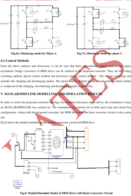
4.1operation of Proposed Converter
As for the developed converter, the operation of each phase includes three modes, which are named as charging,
freewheeling and discharging respectively. For the sake of simplicity, the operations of two phases in a group
are analyzed. Fig 6and Fig 7 depict the operations of Phase A and Phase C in a group respectively. The typical
gate signals and corresponding current profile are shown in the figures below respectively.
Mode 1: Charging
Referring to figure 6(a) if the switching devices Q1,Q4,Q5 are turned ON, then the DC link voltage is applied to
Phase A and then the current rises rapidly in the phase winding. Referring to Fig 7(a) if the switching devices
Q2, Q3, Q6 are switched ON, the phase C is charged through the switches Q2,Q3,Q6. This mode is called as
Fig.6 (a): Charging mode for Phase A Fig.7(a): Charging mode for Phase C
Mode 2: Freewheeling
Referring to Fig 6(b), it can be seen that if the switch Q1 is turned off and Q4, Q5 are still ON, then current
circulates through the switches Q4, Q5 and forward biased diode D2. In the case of Fig7(b), it can be seen that
Phase C freewheels through switches Q2, Q6 and diode D4 when the switch Q3 is turned OFF and the switches
Q2 and Q6 are still ON. In this mode, there is no energy will be transferred between phase winding and Dc
source. This mode is called as Freewheeling mode or unenergized mode.
Fig.6 (b): Freewheeling mode for Phase A Fig.7 (b): Freewheeling mode for Phase C
Mode 3: Discharging
As shown in Fig 6(c) the switches Q1 and Q4 are turned OFF and the switch Q5 is still turned ON in this mode.
Hence Phase A discharges to the DC link capacitor through the diodes D2, D3 and switch Q5. Referring to Fig
7(c) Phase C discharges to the Dc link capacitor through the switch Q6 and the diodes D1 and D4 if the switches
Q2 and Q3 are switched OFF and the switch Q^ is still ON. This mode is called as Discharging mode or
Fig.6(c) Discharge mode for Phase A Fig.7(c) Discharge mode for phase C
4.2 Control Methods
From the above analysis and discussion, it can be seen that three conventional control methods for typical
asymmetric bridge converters of SRM drives can be realized in the proposed converter. They are the voltage
switching method, Speed control method and hysteresis current control method. The voltage switching state
includes the charging and discharging modes. The speed control method and hysteresis current control method
is composed of the charging, freewheeling and discharging modes respectively.
V. MATLAB/SIMULINK MODELLING AND SIMULATION RESULTS
In order to verify the proposed converter topology for switched reluctance motor drives, the simulation is based
on MATLAB/SIMULNK was carried out. The simulation was carried out in both open loop and closed loop
configuration. Along with the proposed converter, the SRM drive with the basic converter circuit is also carried
out.
Fig 8 shows the matlab/simulink model of basic converter circuit fed SRM drive.
Fig.8: Matlab/Simulink Model of SRM Drive with Basic Converter Circuit
Figure 8(a), 8(b), 8(c), 8(d) shows the resultant waveforms of electromagnetic torque , Current, Flux, Speed of
0 0.05 0.1 0.15 0.2 0.25 0.3 0.35 0 50 100 150 Time (seconds) To rq ue T e (N m )
Fig.8 (a) Electromagnetic torque for basic converter circuit of SRM drive
0 0.05 0.1 0.15 0.2 0.25 0.3 0.35
-50 0 50 100 150 200 250 Time (seconds) Cu rre nt (A )
Fig.8 (b) Current for basic converter circuit of SRM drive
0 0.05 0.1 0.15 0.2 0.25 0.3 0.35
-0.05 0 0.05 0.1 0.15 0.2 0.25 0.3 0.35 0.4 0.45 Time (seconds) Fl ux
Fig. 8(c) Flux waveforms for basic converter circuit of SRM drive
0 0.2 0.4 0.6 0.8 1 1.2 1.4 1.6 1.8 2
0 1000 2000 3000 4000 5000 6000 7000 8000 Time (seconds) S p e e d ( R p m )
Fig 9 shows the simulink model of the proposed converter in open loop configuration. The actual speed of the
motor is compared with the reference speed. This gives the speed error in the circuit. The speed error is applied
to the controller which generates the reference current which generates the required gate pulses for driving the
motor. In the open loop system, the controlling cannot be done automatically i.e., the open loop control can only
counteract against disturbances for which it has been designed; the other disturbances cannot be removed.
Fig.9: Matlab/Simulink Model of Proposed Converter in Open Loop Configuration
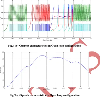
Fig 9(a), 9(b), 9(c) shows the simulation results of electromagnetic torque, current, speed characteristics of the
proposed converter in open loop configuration.
0 0.002 0.004 0.006 0.008 0.01 0.012 0.014 0.016 0.018 0.02
-250 -200 -150 -100 -50 0 50 100 150 200 250
Time (seconds)
<
T
e
(
N
*
m
)>
Fig.9 (a) Torque characteristics in Open loop configuration
As the torque is directly proportional to square of the current, the current waveforms vary according to the
electromagnetic torque. The speed in the open loop is varying through each phase and it is not maintained
constant. Also there will be a slight delay in order to achieve the steady state position i.e. the steady state error
will be high. These are the certain disadvantages in the open loop model, which can be easily overcome by the
0 0.002 0.004 0.006 0.008 0.01 0.012 0.014 0.016 0.018 0.02
-50 0 50 100 150 200 250
Time (seconds)
<
I
(A
)>
Fig.9 (b) Current characteristics in Open loop configuration
0 0.002 0.004 0.006 0.008 0.01 0.012 0.014 0.016 0.018 0.02
0 50 100 150 200 250
Time (seconds)
S
p
e
e
d
(
rp
m
)
Fig.9 (c) Speed characteristics in Open loop configuration
Fig 10 shows the simulink model of proposed converter in closed loop configuration. In this case, the speed
error is passed through a PI controller and a limiter to yield the torque command. From this torque command,
the current command is obtained using the torque constant. This torque constant is for the linearized inductance
vs rotor position characteristics for a particular value of current. The current command is added and subtracted
from the hysteresis window, to determine the switching of the phase and main switches of any converter. The
main advantage of closed loop is that this can counteract to any kind of disturbances. The speed is maintained
constant; Steady state error can be much reduced compared to the open loop configuration.
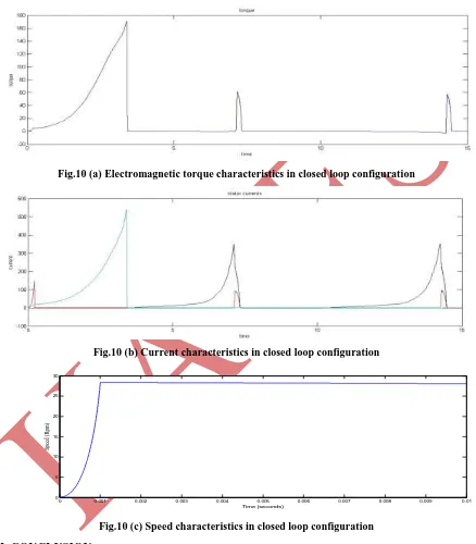
Fig 10(a), 10(b), 10(c) shows the resultant waveforms of Electromagnetic torque, current, speed of SRM drive
of proposed converter in closed loop configuration. Due to the fact that that torque is proportional to square of
current the current varies as per the torque induced in the motor. By using closed loop analysis, the speed can be
maintained constant; the system can achieve fast response compared to open loop model. The torque ripples are
minimized in the case of closed loop compared to that of open loop configuration.
Fig.10 (a) Electromagnetic torque characteristics in closed loop configuration
Fig.10 (b) Current characteristics in closed loop configuration
0 0.001 0.002 0.003 0.004 0.005 0.006 0.007 0.008 0.009 0.01
0 5 10 15 20 25 30
Time (seconds)
Sp
ee
d
(R
pm
)
Fig.10 (c) Speed characteristics in closed loop configuration
VI. CONCLUSION
This paper presented the open loop and closed loop control of four phase 8/6 pole switched reluctance motor
(SRM) drive. When compared to the asymmetric bridge converter, the proposed converter topology consisting
of half-bridge switch modules is more compact and has higher utilization of power switches with lower cost,
without degrading their performance. The control schemes enhanced with the SRM drives are presented. The
simulation in Matlab/Simulink has demonstrated the proposed converter topology. This new converter topology
closed loop control is enhanced all over in order to achieve fast transient response, constant speed of the
machine. This method can be applied for all even numbers of phases of the switched reluctance motor drive.
REFERENCES
[1] Slobodan Vukosavic, Victor R.Stefanovic, “SRM inverter topologies: A comparative evaluation”, IEEE
transactions on industry applications, Vol.27, No.6, pp. 1034-1047, 1991
[2] R.M.Davis and R.J.Blake, “Inverter drive for switched reluctance Motor circuits and component ratings”,
IEEE Proc., pp.126-136, 1981.
[3] J.V. Byrne, et al., “A High performance Variable Reluctance Drive: A New Brushless servo”, Motor
control proceedings, Oct. 1985, pp.147-160.
[4] L.E.Unnewehr and H.W.Koch, “An axial air-gap reluctance motor for variable speed application”, IEEE
Transactions on Power Apparatus and systems, vol. PAS-93, no.1, January, 1974, pp.367-376.
[5] P.J.Lawrenson, “Switched Reluctance Motor Drives”, Elecronics and Power, 1983, pp. 144-147.
[6] R. Krishnan and P.Materu, “Design of a Single-switch-per-phase converter for switched reluctance motor
drives”, IEEE transactions on industrial Electronics, vol. 37, no.6. Pp.469-476, 1990.
[7] C.Pollock and B.W.Williams, “Power converter circuits for Switched reluctance motor with the Minimum
number of switches”, IEEE Proc., vol. 137, Pt. B, n0.6, pp. 373-384, 1990.
[8] T.J.E. Miller. “Electronic control of switched reluctance motors”, Newnes Power Engineering Series
Oxford, UK, 2001.
[9] R.Krishnan, “Switched Reluctance Motor Drives: Modeling, Simulation, Analysis, Design and
Applications”, CRC Press, 2001.
AUTHORS
S.VISHNU VARDHAN
received the B.Tech degree in Electrical and Electronics Engineering from Joginapally Bhaskar Institute of Engineering and Technology,Moinabad, JNTU Hyderabad, Telangana, India in 2012. He is currently working towards
his M.Tech degree in Power electronics and electrical drives (PE&ED) in Mahatma
Gandhi Institute of Technology, Telangana, India. His interested areas are in the field of
power electronics and electrical drives.
Mrs.M.KEDARESWARI
received the B.Tech degree in Electrical and Electronics Engineering from Hi-tech college of Engineering and Technology in 2007 and M.Techdegree in Power electronics and Drives from G.Narayanamma institute of Technology
and Science, Telangana, India in 2012. Currently she is working asAssistant Professor in
Mahatma Gandhi Institute of Technology, Gandipet, Telangana, India. Her interested
areas are in the field of Power electronics and Electrical Drives, Flexible AC transmission