International Journal of Innovative Technology and Exploring Engineering (IJITEE) ISSN: 2278-3075,Volume-8 Issue-6, April 2019
Abstract: Evaluating a grid-tied photovoltaic system performance using DCML inverter and MMC is presented here. The generated output from the PV system is given to the boost converter, and the INCMPPT tracked output is converted to ac with the help of two different methods and connected to the grid. Constant current control technique is used in both the cases for generating the triggering pulses for the inverter. MMC's are having many advantages when compared with the DCML inverter. Both the systems are designed in MATLAB for checking the performance of a 3 level inverter. As per the simulation studies, we can say that a 3 level inverter with MMC is giving less THD when compared with the diode clamped system.
Index Terms: MMC (Modular Multilevel Converter), DCML (Diode Clamped Multilevel Inverter), RES (Renewable Energy Sources).
I. INTRODUCTION
Rapid growth of renewable energy generation is taking place these days as the coal and nuclear fuel are going to deplenish in future. Solar power generation has become more popular as sun is available almost every day. Power generated from solar plant is distributed and utilized by the consumers and the excess power generated is given to the grid [1]. This made the researchers to concentrate on the issues that we will face while connecting to the grid.In present era, power industries are mainly depending on the multilevel inverters. All the multilevel inverter topologies are having some advantages and disadvantages based on their connections [2]. The following are the features that are offered by the multilevel converters: (i) suitable for drive applications (ii) suitable for compensation of reactive power (iii) suitable for power conditioning and (iv) filtering. Out of the available multilevel topologies in the literature we are mainly concentrating on the diode clamped inverter and the modular multilevel converter topologies in this paper.Selecting the DCML inverters for converting the voltage from dc to ac caters low dv/dt and low common mode voltage when compared to the two level inverters. Voltage balancing in the dc link capacitor becomes more complex if we go for higher levels and also the stray inductance effect causes problems.
Revised Manuscript Received on April 07, 2019.
Krishna Chaitanya Diggavi, EEE Department, Guru Nanak Institute of Technology, Hyderabad, Telangana, India.
Lakma Vandana, EEE Department, Guru Nanak Institute of Technology, Hyderabad, Telangana, India.
Posa Naga Sai Jyothi, EEE Department, JBIT, Hyderabad, Telangana, India.
[image:1.595.305.549.256.385.2]Selecting the MMC for converting the voltage from dc to ac caters low THD, good voltage sharing, reduces filter size and also losses. The drawback of the DCML i.e., voltage balancing in dc link capacitor is also eliminated here by applying different voltage balancing techniques.
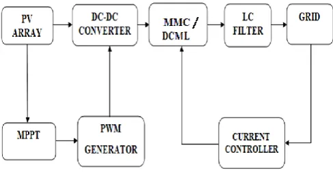
Fig. 1. Flow of grid tied system
The above figure gives us the flow of the grid tied system. In this paper first we have connected DCML in the place of inverter and afterwards we replaced the same with Modular Multilevel Inverter. In both cases the pv system is connected to grid and current control technique is used here for generating pulses to the inverter.
II. PVARRAY MODELING
A Single diode based PV cell model equivalent circuit is shown below.
Fig. 2. Single diode based PV cell
These cells are connected, sealed in a waterproof package forms a module and the series and parallel connection of modules creates an array which gives the required voltage as well as currents [3].
Comparative Analysis of a 3-Level DCMLI and
MMC Based Grid Tied Solar PV System
[image:1.595.306.533.557.666.2]The current equation based on PV voltage is,
I=NP Iph-Np ID [exp(q/kTA*Vpv/Ns )-1] (1)
The diode current equation can be expressed as,
ID=Irr [T/Tr]3 exp((qEG)/kA [1/Tr -1/T]) (2)
The energy gap equation can be given as,
EG=EG(0)-(αT2)/(T+β) (3)
The photocurrent, equation can be formulated using temperature of pv cell and solar radiation as follows,
Iph=[Iscr+Ki (T-Tr)]*S/100 (4)
III. MPPTTECHNIQUE AND BOOST CONVERTER
MPPT methods are used to operate solar pv array in order to extract its maximum power. Out of all the available MPPT techniques incremental conductance MPPT is most preferable as it is more accurate. Flowchart for the same is shown below [4].
[image:2.595.311.545.135.337.2]
Fig. 3. Flowchart for MPPT
If an instantaneous conductance I/V is equals to incremental conductance dI/(dVMPP) then we can say that the output and MPPT voltages are same. Based on the conditions below the MPPT is designed here.
dI/(dVMPP )=(-I)/V
dP/dV=0 At MPP
dP/dV<0 Right of MPP
dP/dV>0 Left of MPP.
The MPPT output is given to boost converter. Based on the increase and decrease of duty cycle, pulses are generated and given to the switch in the boost converter [5]. The output of this is a constant dc voltage. Simulink model of boost converter with mppt is shown below.
IV. DIODE CLAMPED MULTILEVEL INVERTER
[image:2.595.61.275.342.519.2]Inverters plays vital role in the present day power industries as it can be interfaced easily with RES for different applications. It consists of semiconductor switches with control techniques that provide the correct switching pulses to control the inverter output [6].
Fig. 5. Three Level DCMLI
A three-level DCML inverter is considered here, which consists of two capacitors in series and the neutral is center tapped. Clamping diodes Da and Da' are connected to neutral point n. If the switches Sa and Sa' are made on then terminal voltage of inverter is connected to neutral point with any one of the clamping diodes. The resulted output waveform from DCML inverter is a quasi-square wave [7]. In three level inverters, the switching of the upper device will generate +0.5Vd and lower devices in a diode clamped inverter generates -0.5Vd and the output is zero when middle switches are turned.
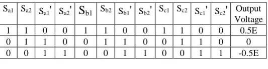
Table 1. Switching states for DCMLI.
Sa1 Sa2 Sa1
'
Sa2'
Sb1
Sb2 Sb1'
Sb2'
Sc1 Sc2 Sc1'
Sc2'
Output Voltage1 1 0 0 1 1 0 0 1 1 0 0 0.5E
0 1 1 0 0 1 1 0 0 1 1 0 0
0 0 1 1 0 0 1 1 0 0 1 1 -0.5E
V. OPERATION OF MMC
[image:2.595.302.569.525.594.2]International Journal of Innovative Technology and Exploring Engineering (IJITEE) ISSN: 2278-3075,Volume-8 Issue-6, April 2019
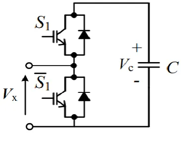
[image:3.595.306.555.121.272.2]Fig. 6. Sub Module of MMC Table 2. Switching states of sub modules.
States S1 S1
'
VxSM Activated 1 0 Vc
SM Deactivated 0 1 0
For getting 3 Level output from MMC we need 2 sub modules in both arms of a leg. The mathematical modeling of MMC is taken from [8]. Based on those equations values of capacitors, inductors are calculated. The switching states for MMC are taken from [9]. The initial voltage of capacitor in each sub module is calculated by using Vdc/n where n represents the no of sub modules. The Simulink model of MMC is given below.
For proper triggering of IGBT’s, current controlling technique is used here [10]. The voltages and currents from the grid are taken as input and converted to required form and compared with the reference values. These compared values are given to PI controllers where the error is eliminated and the required pulses are generated with the help of PWM generator.
VI. SIMULATION RESULTS
sThe simulated results discussed here is for a DCML and MMC based grid tied systems. Current controlling technique is used in both the cases to get desired output from the inverter. THD values of 3 level inverter voltages are compared in both the cases. The complete Simulink model of the above said system is given below.
Fig. 7. Simulink model of DCML/MMC based system.
Case-i: DCML based grid tied system
[image:3.595.40.295.249.287.2]The phase to ground and phase to phase output voltage of DCML inverter is shown in figure.8 & 9 respectively.
Fig. 8. Phase to ground voltage of DCMLI
Fig. 9. Phase to Phase voltage of DCMLI
THD values for the above voltage waveforms are shown in the following figures.
[image:3.595.304.554.298.466.2] [image:3.595.306.549.540.695.2] [image:3.595.48.296.601.748.2]Fig. 11. THD value of Phase to Phase voltage Case-ii: MMC based grid tied system
[image:4.595.48.288.50.207.2]The phase to ground and phase to phase output voltage of MMC is shown in figure.12 & 13 respectively.
Fig. 12. Phase to Ground voltage of MMC
Fig. 13. Phase to Phase voltage of MMC.
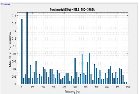
[image:4.595.310.544.243.401.2]THD values for the above voltage waveforms are shown in the following figures.
Fig. 14. THD value of Phase to Ground voltage
[image:4.595.49.290.305.466.2] [image:4.595.54.287.492.670.2]Fig. 15. THD value of Phase to Phase voltage. Table.3 shows the comparison of THD of output voltage for a DCML and MMC based grid tied systems before filter.
Table 3. Comparison of THD for DCML and MMC Method THD value of Phase to
Ground Voltage
THD value of Phase to Phase Voltage
DCMLI 74.34% 45.89%
MMC 52.31% 39.92%
VII. CONCLUSION
[image:4.595.299.554.500.574.2]International Journal of Innovative Technology and Exploring Engineering (IJITEE) ISSN: 2278-3075,Volume-8 Issue-6, April 2019
REFERENCES
1. Gopal Nath Tiwari, Rajeev Kumar Mishra., "Advanced Renewable Energy Sources" RSC Publishing.
2. L. M. Tolbert and F. Z. Peng, “Multilevel converters as a utility interface for renewable energy systems,” in Proc. IEEE Power Eng. Soc. SummerMeet., Seattle, WA, USA, Jul. 2000, pp. 1271–1274
3. J Xuan Hieu Nguyen and Minh Phuong Nguyen, “Mathematical modeling of photovoltaic cell/module/arrays with tags in Matlab/Simulink” in Enivronmental systems research, Springer in 2015.
4. Ramli, M.A.M., Twaha, S., Ishaque, K., Al-Turki, Y.A, “A review on maximum power point tracking for photovoltaic systems with and without shading conditions” in Renew. Sustain. Energy Rev. 67(January), 144–159 (2017).
5. K. Gummi, “Derivation of New Double Input DC-DC Converters Using the Building Block Methodology “, M. Sc Thesis, Missouri University of Science and Technology, 2008.
6. Parth S. Joshi ; Chetan V. Sheth., “Modelling of grid tied 3-level diode clamped inverter using space vector PWM for PV system” in 5th Nirma University International Conference on Engineering (NUiCONE) 2015. 7. Mariah Binte Marzuki ; R.T. Naayagi ; Van-Tung Phan., “Modelling and
simulation of Multilevel Inverter for grid connected Photovoltaic system” in IEEE Region 10 Conference (TENCON) Singapore, 2016.
8. Krishna Chaitanya Diggavi, B. Pakkiraiah., “Comparative Analysis of a 2-Level and 3-Level Constant Current Controller Based MMC for Grid Tied Solar PV System” in Jour of Adv Research in Dynamical & Control Systems Vol. 10, 09-Special Issue, 2018.
9. Harini.M.Mohan, Vanitha.V, M.Jayakumar.,” Comparison of PWM techniques for a three level Modular Multilevel Inverter” in International Conference on Power Engineering, Computing and Control, VIT University in 2017.