Abstract: Ambient computing is a rapidly growing field which requires increasing number of wireless devices. In this paper first a hexagonal shape patch antenna is designed. Fractal concept is used to achieve miniaturization. So triangle inscribed hexagon fractal patch antenna is designed. The designed antenna is simulated using Computer Simulation Technology (CST) Microwave Studio software. The proposed antenna resonates in the range of 2 GHz to 10 GHz. Mechanical tuning in frequency is achieved by varying the ground length. Good reflection coefficient less than -10dB, gain, E and H fields are observed in CST. Then fuzzy logic model is developed in MATLAB software for movable ground. Mechanical sliding ground results and fuzzy logic model results are compared. This antenna is adaptive and anticipatory, can be utilized where stable system is required because it provides more robustness. This paper explores the use of fractal reconfigurable antennas to aid the development of ambient computing.
Index Terms: Ambient intelligence, antenna, fractal, fuzzy logic, micro strip patch, mechanical tuning, reconfigurable.
I. INTRODUCTION
Ambient computing, a new paradigm can be defined as a widespread discipline which works in the area of environment, society, security, computing, interacting, intelligence and many more. It’s a future vision technique [1]. Ambient Intelligence (AmI) is next to ubiquitous computing where it senses people’s presence in electronic environment. The main requirement of AmI is distribution, ubiquitous, transparent and intelligent. Now in the modern–era of ambient intelligent world, network-intelligent devices will provide all information and communication to user at any location [2]. There are five attributes of ambient intelligence. Embedded: integrated devices; context aware: situation awareness; personalized; adaptive: changes as per user and anticipatory [2, 3]. These features are similar to human behaviour as cognitive, context awareness, personal, adaptive and anticipatory.
Revised Manuscript Received on April 7, 2019.
Anita Garhwal, Amity University Rajasthan, Jaipur, India.
Mohd Riduan Ahmad,Centre for Telecommunication Research and Innovation (CeTRI), Universiti Teknikal Malaysia Melaka (UTeM), 76100 Durian Tunggal, Melaka, Malaysia.
Badrul Hisham Ahmad, Faculty of Electronic and Computer Engineering, Universiti Teknikal Malaysia Melaka, Melaka, Malaysia.
Sanyog Rawat, Manipal University Jaipur, India
Pushpendra Singh, Amity University Rajasthan, India.
Kanad Ray, Corresponding author: Amity University Rajasthan, India.
Anirban Bandyopadhyay, National Institute for Material Science, Japan.
AmI application in smart home is described in [4]. Smart home is having basically three domains: comfort, health and security [5]. It is having application is all areas like homes, hospital (health), education, transport etc. [6]. Using AmI, climate big data is captured and analysed for dengue transmission [7]. Intelligent transportation system using AmI is developed [8], intelligent wireless Qos technology in WLAN [9], ambient concept in educational institute [10] and smart content selection for public display using AmI [11]. AmI is providing better everyday life. Ambient computing is leading to huge expansion in demand of wireless communication services. There is necessity of re configurable antennas so total number of antennas are reduced and flexibility of wireless devices is increased. Earlier antennas were designed only for one specific parameter like gain, bandwidth, radiation pattern, directivity etc. but nowadays smart antennas are designed that can handle more than one parameter at a time. For Example, cognitive radios which sense the environment and allocate the available spectrum. Reconfigurable antenna is a better choice because in this we can control antenna parameters electrically, mechanically and optically to achieve better signal to noise radio, low interference, radio spectrum utilization and improved capacity. Here we can combine many smaller front –end units to get smart antenna array, so overall size of antenna is less and implementation cost is also reduced. Re configurability can be controlled in three ways i.e. electrical, mechanical and optical.
Conventional switching method uses pin diode [12], varactors or RF-MEMS switches [13], among these pin diode is more popular in reconfigurable antenna design. These methods have low reliability, low tuning and limited power handling because solid state switches have low linearity issues. Here controlling is electrical in nature by redirecting the surface current.
Due to high power, system can heat up and burst. Alternative of this method is mechanical reconfigurable antenna, because here less signal interference and isolation issues as mechanical actuators do not require to be placed in antenna signal path. Also, mechanically tuning is slow but it is stable, high power handling capabilities and linearity. Conventional actuators were heavy, bulky and high power consuming but now with the advancement in VLSI integration methods and smart materials (electro active polymers) these are easy and cheap [14].
Applications of reconfigurable antennas are in cellular radio system, radar system,
wireless communication (Wi-Fi, WiMAX etc.),
Mechanically Reconfigurable Hexagonal Fractal
Patch Antenna for Ambient Computing
airplane and smart weapon protection, cognitive radio and radio spectrum management [14]. There are three types of reconfigurable antennas:-
1. Frequency reconfigurable 2. Polarization reconfigurable 3. Radiation pattern reconfigurable
Frequency reconfigurable: - Those antennas where operating frequency is electrically controlled without altering the radiation characteristics of the design are known as frequency reconfigurable. This can be done by switched tuning or continuous tuning, where antenna resonant frequency is changed discrete in nature and continuous in nature respectively [15].
Polarization reconfigurable:- those antennas where polarization changes from horizontal to vertical, at an angle, left and right-hand polarization [13]. For example, antenna can change from right hand to horizontal. Radiation pattern reconfigurable: -here radiation pattern is tuned in terms of shape (directivity), direction and value (gain).
Advantages of reconfigurable antenna over normal antenna are reduction in size, weight, cost and complexity. It also offers secure, multiband and anti-jamming capabilities. Electrically control antennas are implemented in literature. Advantages of mechanical control over electrical are better reliability even though with slower tuning, good control over antenna and robust techniques [16]. Here some mechanical movements are involved. Optical reconfiguration is done with the help of laser and optical fibre but this technique is costly. Many mechanically reconfigurable antenna papers are presented for cognitive radio. Software controlled ground plane antenna is presented for cognitive radio where there are two fixed grounds and one moving is used. Frequency tuning is done by elevating and tilting of ground plane 5]. Mechanical tuning using electromagnetic coupling is done in [17]. Meandered line antenna is developed and fabricated by making ground plane floating [18-19]. In this the ground below the meander patch is floating and same is achieved with the help of copper wires. Resonating frequency changes as the wires are removed one by one. This antenna structure gives multi-frequency response with better radiation pattern. A sensing and reconfigurable antenna is given in [20]. To achieve frequency re configurability, antenna patch consisting five different shapes is rotated by stepper motor. Each shape resonates in different band.
Mechanical reconfiguration is also obtained by using the galinstan liquid metal in [21]. Here the same meander patch described in [20] is used. Frequency re-configurability is achieved by injecting galinstan liquid from different lengths of patch using syringe. So as the metal pressure changes frequency changes. Antenna for polarization diversity is given in [22]. One bottom substrate and second upper substrate is used. The bottom substrate have fixed L-probe feed and upper one have truncated patch that rotates in azimuth direction. A thin bolt is used for tiding two layers together. In [23] for manual reconfiguration patch of antenna is rotating and this patch consists of four different shapes. To achieve different resonating frequency patch is rotated at clockwise 4500,
actuator based mechanical reconfiguration. In [19], [22-25] manual re configurability is achieved.
Fractal concept is acquired from Latin word “fractus” that refers to broken. Fractal is generated using recursive methods where same structure is regenerated from the base structure but smaller in size [26]. Fractal geometries have two properties, one is space filling which is utilized for antenna miniaturization where large electrical antenna length can be fit in smaller areas and second is self-similarity which is used to get multi band operation [27, 28]. Degree of miniaturization increases by changing the fractal dimension of antenna. Many fractal patch antennas with hexagonal shape are presented in literature [29-35].
This paper is further divided into 4 sections: - in section -2 methodology used, in section -3 fractal hexagonal antenna design with simulated results is presented, while section-4 has results and discussion of mechanical reconfigurable antenna, section-5 has fuzzy logic model of movable ground.
II. METHODOLOGY
1. Hexagonal-triangle fractal patch antenna is designed and simulated in CST software.
2. Antenna ground is divided into two parts: fixed and movable.
3. Movable (sliding) ground design is simulated in CST for different length positions: 1/8, 1/4, 1/2, 3/4, 4/4.
4. Fuzzy logic model is developed using MATLAB software for movable ground for applications in ambient environment/ intelligence.
5. Mechanical sliding ground results and fuzzy logic model results are compared and validated.
III. ANTENNADESIGN
Fig 1: Antenna Geometry Iteration-0
[image:3.595.45.281.85.505.2]Reflection coefficient is shown in fig 2. Surface current distribution of hexagon is shown in fig 3. The antenna resonates at frequency 3.57GHz, 6.0 GHz and 7.77 GHz with S11 of -17.13,-18.71, and -18.76.
Fig 2: Reflection Coefficient of Hexagonal Patch
(a) Fr=3.57 GHz (b) Fr=6.0 GHz
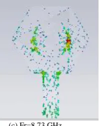
(c) Fr=7.77 GHz
Fig 3: Surface Current in Hexagon
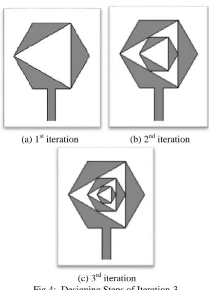
In fig 3 the current flows only at the edges of hexagon and feed line. There is no current in middle area, so we can introduce fractal geometry inside the patch. 1st iteration is achieved by removing a triangle of side length 14.5mm from alternative edges of hexagon. By doing this electrical length for current is increased so antenna size is miniaturized. To achieve 2nd iteration, first a hexagon is inscribed and later a triangle is removed of side length 8.6mm. In the similar fashion iteration-3 is achieved by inscribing a hexagon first and then removing a triangle of length 5.1mm. In this geometry space filling fractal property is applied to get miniature antenna. Different iterations are shown below in fig 4. In literature square inscribed square also known as crown square [36], Triangular wheel shape fractal [37], circle inscribed circle fractal [38], square slot in circular patch [39], square octal fractal [40] are presented. Octagon and decagon shaped fractal patch antenna presented [42]. Nature inspired and biological antennas are also presented [43-50].
(a) 1st iteration (b) 2nd iteration
(c) 3rd iteration
Fig 4: Designing Steps of Iteration-3
[image:3.595.311.557.420.500.2]Comparative reflection coefficient for different iterations is shown in fig 5. When we are applying fractal geometry and increasing iterations then resonating frequency is shifting from 3.5GHz to 3.28GHz is achieved so antenna size is reduced. Better results are achieved in iteration-3.
[image:3.595.307.549.536.620.2]Fig 5: Reflection Coefficient for Different Iterations
Fig 6: Gain for Different Iterations
Table I: Comparative Study of Different Iterations
Iteration Fr Fl Fh BW % Gain
(dB)
0th 3.57
3.04 9.12
35.06% 2.14
6.0 1.38
7.77 3.42
1st 3.30 2.82 5.74 88.48% 2.06
6.99 6.40 7.33 13.30% 2.79
2nd 3.3 2.82 5.41 78.49% 2.02
8.3 7.62 9.04 17.11% 4.26
3rd 3.28 2.81 6.60 39.07% 2.02
6.42 2.59
8.73 8.39 9.31 10.53% 4.60
(a) E field (b) H field
Fig 7: Radiation Pattern of E and H plane E and H plane radiation pattern for iteration-3 is shown in fig 7. E field pattern is achieved when phi=00 while for H plane phi=900. At 3.28 GHz and 6.42GHz E field radiation pattern is omni directional and H field pattern is eight shape for all resonating frequencies. Surface current distribution for iteration -3 is shown in fig 8.
(a) Fr=3.28GHz (b) Fr= 6.42 GHz
[image:4.595.47.295.72.550.2]
(c) Fr=8.73 GHz
Fig 8: Surface Current Distribution of Iteration -3
[image:4.595.63.275.629.759.2]When resonating frequency is lower, 3.28 GHz, then maximum current flows through feed line. At 6.42GHz some current flows in outer heaxgon and maxium flows into inner ones. Current flows only in inner hexagon at 8.73 GHz. Here effective current path length is increased as compred to 3.28 GHz.
Table II: Comparison of Hexagonal Fractal Patch Antenna
Referen ce no.
Dimensions Frequency and Gain
[41] Patch =45 * 44 Gain= 2.88dB
1.9, 2.6 GHz
[27] Radius of circle fits=18.24
3.94,6.46,13.04,14.16
Gain= - 6.85, 4.11, 3.73, 3.11 dBi respectively.
[34] 45mm*44.92 mm.
Frequency band is 3.1 to 10 GHZ. Fr=3.14GHz, 4.87GHz, 5.74GHz, 6.55GHz, 8.62GHz and 9.85GHz. Gain= 8.80, -2.74, 2.53, 3.34, 5.38 and 7.59 respectively.
Propose d
Antenna
28*28 mm (2.8- 6.4 GHz) band with resonating frequencies 3.28 GHz, 6.42GHz and (8.39-9.31 GHz) band with resonating frequency 8.73 GHz.
Gain=2.0, 2.5 and 4.6 dB respectively. Bandwidth of about 39% is achieved in iteration-3.
Comparison of hexagon shape fractal patch antenna is given in table-2. The proposed antenna is having the lowest size.
IV. MECHANICALTUNINGOFGROUND
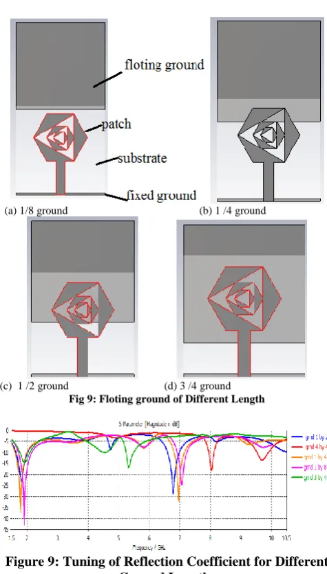
Mechnical tunning is achieved in similar fashion to [19]. Here total ground length is dvided into two parts, one is fixed and other is floting. Total ground length is 28mm. Out of which 1.0mm is kept fixed and 27mm is floting ground. Then we will slide floting ground vertically down over fixed ground. For 1/8th ground, ground length will be 3.5mm, out of which 1.0mm is fixed so floting ground till of 2.5mm is sliding vertically.
(a) 1/8 ground (b) 1 /4 ground
(c) 1 /2 ground (d) 3 /4 ground
[image:5.595.47.285.38.456.2]Fig 9: Floting ground of Different Length
Figure 9: Tuning of Reflection Coefficient for Different Ground Lengths
[image:5.595.306.549.53.160.2]Reflection coefficient for different ground length is shown in fig 10. When we are manually sliding the ground plane then contact between substrate and floting ground changes so resonating frequency also changes. Frequency re configurability is shown in table III.
Table III: Frequency and Gain for Different Ground Length Sr.no. Ground Fr (GHz) Band (GHz) Gain
(dB)
1. 1/8 1.91
7.06
1.72-2.15, 6.92-7.23
0.6 -2.1
2. 1/4 1.78
6.97
1.61-1.99 6.97-7.15
2.4 1.0
3. 1/2 1.81
6.78
1.65-2.02 6.60-6.98
1.9 1.2
4. 3/4 1.92
5.33
1.77-2.09 5.24-5.49
-1.8 1.7
5. 4/4 8.03
9.70
7.95-8.12 9.54-9.90
3.3 2.8 From the above table it is clear that the designed antenna covers frequency band of 1.61 GHz to 2.15 GHz ( L band) and 5 GHz to 10 GHz ( C and X band). So this antenna is useful for multiband applications. Gain for different grounds is shown in fig 11. Here gain is positive at all frequencies except at 7.06 GHz and 1.92 GHz.
Figure 10: Gain for Different Ground Lengths
So a single antenna can be utilized for different ground lengths. This technique is cost effective and easy to implement, because instead to fabricating 5 different antennas all can be accommodated in one. When we slides the floating ground then effective length of ground is increased and different resonating frequencies are achieved. From the table 3 and return loss graph in fig 10 that when the ground length is increased then band shifts.
The designed antenna works in 1-10 GHz range, this can be used for Cognitive radio. Mechanical reconfiguration is used because system is more stable in comparison to electrical tuning although mechanical tuning is slower than electrical. This antenna can be a utilized where we require stable systems because it provides more robustness.
V. FUZZYLOGIC
Fuzzy logic is a multivalued logic system. Fuzzy logic is applied on the antenna system for applications in ambient environment. Because ambient intelligence is sensitive, adaptive and responsive to user. Fuzzy logic for ambient environment is prseneted in literature [51-53]. The propsed system can be a good candidate where a single antenna with the help of sliding ground can be utilized for many applications. The proposed system is easy to handle and cost effective.
[image:5.595.48.291.547.666.2]Fuzzy logic is applied here for decision making, when a certain frequency is detected by antenna, then by sliding, movable ground should reach there. For this input membership function of fuzzy logic is “frequency” and output membership function ground length is defined in MATLAB. Fuzzy logic system is shown in figure 12, input and output membership functions are given in Table –IV. Mamadani rules are defined.
[image:5.595.305.550.590.691.2]Table IV: Input and Output Membership Function
Input membership function Output membership function
Frequency (membership function) Ground length
1.78 GHz Very low 1/4=0.25
1.81 GHz Moderate low ½ =0.5
1.91 GHz Low 3/4 =0.75
5.33 GHz Very medium 3/4= 0.75
6.78 GHz Medium 1/2= 0.5
6.97 GHz High 1/4=0.25
8.03 GHz Moderate high 4/4=1
9.70 GHz Very high 4/4=1
If then Else rules are defined as:
1. IF ground length is very low then ground length is 1/4. 2. IF ground length is moderate low then ground length is 1/2. 3. IF ground length is low then ground length is 3/4. 4. IF ground length is very medium then ground length is 3/4. 5. IF ground length is medium then ground length is 1/2. 6. IF ground length is high then ground length is 1/4. 7. IF ground length is moderate high then ground length is 4/4. 8. IF ground length is very high then ground length is 4/4.
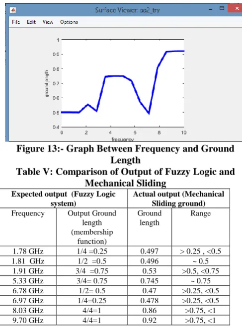
[image:6.595.42.286.368.699.2]Fuzzy system output graph between frequency and ground length is shown in figure 13. The output of fuzzy logic system is comptble with mechanical sliding ground results shown in below table V.
Figure 13:- Graph Between Frequency and Ground Length
Table V: Comparison of Output of Fuzzy Logic and Mechanical Sliding
Expected output (Fuzzy Logic system)
Actual output (Mechanical Sliding ground)
Frequency Output Ground length (membership
function)
Ground length
Range
1.78 GHz 1/4 =0.25 0.497 > 0.25 , <0.5
1.81 GHz 1/2 =0.5 0.496 ~ 0.5
1.91 GHz 3/4 =0.75 0.53 >0.5, <0.75
5.33 GHz 3/4= 0.75 0.745 ~ 0.75
6.78 GHz 1/2= 0.5 0.47 >0.25, <0.5 6.97 GHz 1/4=0.25 0.478 >0.25, <0.5 8.03 GHz 4/4=1 0.86 >0.75, <1 9.70 GHz 4/4=1 0.92 >0.75, <1
VI. CONCLUSION
A novel fractal patch antenna with hexagon inscribed triangle is presented which can aid in development of ambient
emphasis of this paper is to achieve a system which provides frequency tuning and cost effective. This mechanical reconfigurable antenna has the ability to be context aware, adaptive and anticipatory. Ambient computing environment such as a smart home, mostly consists of large number of small devices. These devices require an antenna which can provide flexibility, can be miniaturized easily and is cost effective. The antenna concept presented in this paper can be adapted for ambient computing.
REFERENCES
1. S.E. Bibri, “Ambient Intelligence: A New Computing Paradigm and a Vision of a Next Wave in ICT”, The Human Face of Ambient Intelligence, Atlantis Ambient and Pervasive Intelligence, 2015. 2. Emile Aarts, “Ambient Intelligence: A Multimedia Perspective”, IEEE
Computer Society, 2004.
3. E. Aarts and S. Marzano, eds., The New Everyday: Visions of Ambient Intelligence, 010 Publishing, Rotterdam, The Netherlands, 2003. 4. Frederick Hutchinson, “A Literature Review of Modern Ambient
Intelligence Smarthomes”.
https://www.cs.auckland.ac.nz/courses/compsci705s2c/assignments/re
ports/2014/Ambient%20Intel.pdf
5. Alam, M. R., Reaz, M. B. I., and Ali, M. A. M. A review of smart homes past, present, and future. Systems, Man, and Cybernetics, Part C: Applications and Reviews, IEEE Transactions on 42, 6 (2012), 1190–1203.
6. Juan Carlos Augusto and Paul McCullagh, “Ambient Intelligence: Concepts and Applications”, Comput. Sci. Inf. System, 2007. 7. Gunasekaran Manogaran, Daphne Lopez, “Disease Surveillance System
for Big Climate Data Processing and Dengue Transmission, International Journal of Ambient Computing and Intelligence (IJACI), vol.8, issue 2, 2017.
8. Wenli Yang, Xiaojing Wang, Yun Yang, Srikanta Patnaik, “Design of Intelligent Transportation System Supported by New Generation Wireless Communication Technology”, International Journal of Ambient Computing and Intelligence, volume 9, issue 1, January-March 2018.
9. Dharm Singh Jat , Lal Chand Bishnoi and Shoopala Nambahu, “An Intelligent Wireless QoS Technology for Big Data Video Delivery in WLAN”, IJACI, vol.9, issue 4, 2018.
10. Vladimír Bureš, Petr Tučník, Peter Mikulecký, Karel Mls, Petr Blecha, “Application of Ambient Intelligence in Educational Institutions: Visions and Architectures”, IJACI, vol,-7, issue-1, 2016.
11. Fernando Reinaldo Ribeiro and Rui José, “Smart Content Selection for Public Displays in Ambient Intelligence Environments”, IJACI, volume 5, Issue 2, April 2013.
12. N. Haider, D. Caratelli, and A. G. Yarovoy, “Recent Developments in Reconfigurable and Multiband Antenna Technology”, International Journal of Antennas and Propagation, January 2013.
13. Christos G. Christodoulou, Youssef Tawk, Steven A. Lane, and Scott R. Erwin, “Reconfigurable Antennas for Wireless and Space Applications”, Proceedings of the IEEE vol. 100, No. 7, July 2012. 14. J.Shahrzad “A review of mechanically reconfigurable antennas using
smart material actuators”, proceedings of 5th European Conference on Antennas and Propagation (EuCAP).
15.Manoj S Parihar, Ananjan Basu, and Shiban K Koul, “Reconfigurable Printed Antennas”, IETE Journal of Research, vol. 59, Aug.2013, pp 383-391.
16.J. Costantine, Y. Tawk, C. G. Christodoulou, “A Reconfigurable Antenna with Software Controlled Ground Plane”, IEEE 2013. 17.Jennifer T. Bernhard, E. Kiely, and Gregory Washington, “A Smart
Mechanically Actuated Two-Layer Electromagnetically Coupled Microstrip Antenna with Variable Frequency,Bandwidth, and Antenna Gain”, IEEE transactions on antennas and propagation, vol. 49, no. 4, april 2001.
18.Jean Marie Floch, Abhishek Singh, Laurent Desclos, “Set of New Compact Antennas Suitable for Integration on PCB”, Loughborough Antennas and Propagation Conference (LAPC), 10-11 November, 2014, UK.
Antennas and Propagation (EuCAP), IEEE 2016.
20.Y. Tawk, J. Costantine, K. Avery, and C. G. Christodoulou, “Implementation of a Cognitive Radio Front-End Using Rotatable Controlled Reconfigurable Antennas”, IEEE transactions on antennas and propagation, vol. 59, no. 5, MAY 2011.
21. J.m. Floch, I. Ben trad, “Design of mechanically reconfigurable meander antenna using the Galinstan liquid metal, IEEE 2017. 22.Ian T. McMichael, “A Mechanically Reconfigurable Patch Antenna
with Polarization Diversity”, IEEE Antennas and Wireless Propagation Letters, 2018.
23.Y. Tawk, J. Costantine, C. Christoulou, “A Frequency Reconfigurable Rotatable Microstrip Antenna Design,” IEEE Antennas Propagation Soc. Intl. Symp., pp. 1 – 4, 2010.
24.C. Sun, H. Zheng, L. Zhang, Y. Liu, “A Compact Frequency Reconfigurable Patch Antenna for Beidou (COMPASS) Navigation System,” IEEE Antennas Wireless Prop. Letter vol. 13, pp. 967 – 970, 2014.
25.H. Zhu, S. Cheung, X. Liu, T.Yuk, “Design of Polarization Re configurable Antenna Using Metasurface”, IEEE Trans. Antennas Propagation, vol. 62, no. 6, pp. 2891 – 2898, 2014.
26. Sneha Suresh Kadam, Prof. Mahesh, S. Mathpati, “High Gain Compact Hexagonal Fractal Antenna”, IOSR Journal of Electronics and Communication Engineering, “Volume 9, Issue 6, PP 74-77, Ver. IV, Nov - Dec. 2014.
27. Mukh Ram, Sushrut Das, Ram Lal Yadava, “A Hexagonal Multiband Fractal Patch Antenna”, IEEE-2015.
28. John P. Gianviffwb and Yahya Rahmat-Samii, “Fractal antennas: A Novel Antenna Miniaturization Technique and applications”, IEEE Antenna’s and Propagation Magazine, Vol. 44, No. 1, February 2002. 29. Indranil Acharya, Sameer Mohan and Prateek Thawait, “A Novel
Hexagonal antenna with L-strip proximity gap coupling for 2.4 GHz and WiMAX applications”, 3rd International Conference on Signal Processing and Integrated Networks (SPIN), IEEE 2016.
30. A. A. Lotfi-Neyestanak, M.R. Azadi and A. Emami-Forooshani, “Compact size ultra wideband hexagonal fractal antenna”, 25th Biennial Symposium on Communications, IEEE, 2010.
31. Djelloul Aissaoui, Noureddine B. Hacen and Tayeb A. Denidni, “UWB Hexagonal Monopole Fractal Antenna with Additional Trapezoidal Elements”, IEEE International Conference on Ubiquitous Wireless Broadband (ICUWB), 2015.
32. N.A. Saidatul, A.H.Azermi, P.J. Soh, “A hexagonal fractal antenna for multiband applications”, Internationl Conference on Intelligent and Advanced Systems, IEEE, 2007.
33. V. Ashok, S Uma Maheshwari, “Miniaturized UWB microstrip fractal antenna”, International Conference on Circuit, Power and Computing Technologies, IEEE, 2016.
34. Narinder Sharma, Jaspreet Singh, Vipul Sharma, “Design of Hexagonal Meander fractal antenna for Multiband applications”, ICMETE, IEEE, 2016.
35. M.Sreerag, T.Sudha, “A Hexagonal boundary fractal antenna with WiMAX band rejection”, NCCSN, IEEE, 2014.
36. Hemant Singh Bisht, Dr. A. N. Mishra, Sanjeev Budhauliya, “design of square shape crown microstrip fractal antenna”, IJARSE, Vol. No.4, Issue 04, April 2015.
37. Raj Kumar, P. Malathi, “On the Design of CPW- Fed Ultra Wideband Triangular Wheel Shape Fractal Antenna”, International journal of microwave and optical technology, vol.5 no.2 MARCH 2010. 38. Mohandoss Susila, T. Rama Rao, Aman Gupta, “A Novel Smiley Fractal
Antenna (SFA) Design and Development for UWB Wireless Applications”, Progress In Electromagnetics Research C, vol. 54, 2014, pp. 171-178.
39. Nagendra Kushwaha, Raj Kumar, “An UWB fractal antenna with defected ground structure and swastika shape electromagnetic band gap”, Progress In Electromagnetics Research B, vol. 52, 383-403, 2013. 40. Raj Kumar, J P Shinde, P N Shinde and M D Uplane, “On the Design of CPW-Fed Square Octal Shaped Fractal UWB Antenna”, IEEE, 2009. 41. Deepshikha Yadav, DC Dhubkarya, “Design of hexagonal fractal
antenna for wlan/ wimax & bluetooth applications”, IJRET, vol. 03 Issue: 12, Dec-2014.
42. Anita Garhwal, Nornikman Hassan, Mohd Riduan Ahmad, Badrul Hisham Ahmad, Sanyog Rawat, Pushpendra Singh, Kanad Ray, Anirban Bandyopadhyay, “Octagon and Decagon shaped Fractal Patch Antennas for S, C and X band Applications”, International Journal of Recent Technology and Engineering (IJRTE), vol. 7, Issue 6, March 2019.
43. P. Singh, K. Ray, S. Rawat, “Design of nature inspired broadband microstrip patch antenna for satellite communication”, Advance and
Nature and Biologically Inspired Computing, vol.419, Nov. 2015, pp. 369- 379.
44. P. Singh, R. Doti, J.E.Lugo , J.Faubert, S.Rawat, S.Ghosh, K. Ray and A.Bandyopadhyay, ,“DNA as an electromagnetic fractal cavity resonator: Its universal sensing and fractal antenna behavior”, AISC. vol. 584, 2017, pp. 213-223.
45. P. Singh, K. Ray, S. Rawat, “Nature inspired sunflower shaped microstrip antenna for wideband performance” International Journal of Computer Information System and Industrial management Applications (IJCISM), ISSN 2150-7988, vol. 8, 2016, pp. 364-371.
46. P. Singh, M. Ocampo, J.E. Lugo, R. Doti, J. Faubert, S.Rawat, S. Ghosh, K. Ray and A. Bandyopadhyay, “Fractal and periodical biological antennas: hidden topologies in DNA, wasps and retina in the eye” Studies in Computational Intelligence, Springer, Soft computing application vol. 761, 2018, pp. 113-130.
47. P. Singh, R. Doti, J.E.Lugo, J.Faubert, S.Rawat, S.Ghosh, K. Ray and A.Bandyopadhyay,“Frequency Fractal Behaviour in the Retina Nano Centre- Fed Dipole Antenna Network of a Human Eye” AISC. vol. 584, pp. 201-211, 2017.
48. S. Rawat, U. Keshwala, and K. Ray, “Compact Design of Modified Pentagon Shaped Monopole Antenna for UWB Applications,” International Journal of Electrical and Electronic Engineering & Telecommunications vol. 7, No. 2, pp. 66-69, 2018.
49. Singh, P., Ray, K. & Rawat, S. “Analysis of Sunflower shaped monopole antenna”, Wireless Pers Commun (2019) 104: 881. https://doi.org/10.1007/s11277-018-6056-z
50. Ushaben Keshwala, Sanyog Rawat, Kanad Ray, Nivedita Nair and Shweta Yadav, “Compact circular monopole antenna with band notch characteristics for UWB applications”, 5th International Conference on Signal Processing and Integrated Networks (SPIN), 2018, pages-312-315,978-1-5386-3045-7/18/$31.00 ©2018 IEEE. 51. Teresa Garcia-Valverde, Alberto Garcia-Sola, Hani Hagras, James A.
Dooley,Victor Callaghan, and Juan A. Botia, “A Fuzzy Logic-Based System for Indoor Localization Using WiFi in Ambient Intelligent Environments”, IEEE Transactions on Fuzzy Systems, vol. 21, no. 4, August 2013.
52. G. Acampora and V. Loia, “Fuzzy control interoperability and scalability for adaptive domotic framework,”IEEE Trans. Ind. Informat., vol. 1, no. 2, May 2005, pp. 97–111.