International Journal of Innovative Technology and Exploring Engineering (IJITEE) ISSN: 2278-3075, Volume-8 Issue-7, May, 2019
Abstract: In wireless sensor networks (WSN), energy efficiency is of critical concern as the sensor nodes are powered by limited battery capacity. The choice of a modulation scheme and error control code plays an important role in determining the energy consumption of WSN. This paper analyses the performance of error control codes and various modulation schemes for WSN. The analysis reveals that the energy consumption in WSN can be decreased by a suitable choice of modulation scheme and error control codes. Our simulation results show that by using BPSK modulation with Reed Solomon (RS) code saves 48 % energy in WSN at an internode distance of 60 meters in comparison to higher order modulation schemes.
Index Terms: Energy Efficiency,Error Control Codes Modulation Scheme, Wireless Sensor Networks,
I. INTRODUCTION
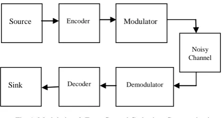
A WSN consists of autonomoussensorsthat keeps a track onnatural environmental conditions, liketemperature, vibration, motion, level of pollutants etc., and communicate with each other the data viaa network to a sink. A basic communication system using modulation and error control coding is shown in Fig.1. Here, the information source is a sensor which measures the data (e.g. temperature, light, humidity etc.). This data is encoded using an error control code (linear or convolution codes). Finally, data is transmitted using a suitable modulation scheme e.g.ASK, FSK, PSK. At the receiver, the reverse process at the transmitter is performed to receive the data. The energy consumption of a WSN node depend s on the distance between receving node and transmitting node , choice of Bit Error Rate (BER), modulation techinques and error control code (ECC). S. Chouhan et al. [1]have investigated node energy variations based on used ECC and modulation parameters. Additive white Gaussian noise (AWGN) channel is considered for energy-optimal node design for the nodes. S. Cui, et al. [2] have studied transmission energy, circuit energy, transmission time, and constellation size for both uncoded and coded M-QAM and M-FSK and corresponding tradeoffs. Multi-level (M-ary) modulation and. binary modulation schemesare compred by A.Y. Wang, et.al. [3]. It is found that energy efficiency of former is better than the later one for the case with shortstart-up time and smaller RF output power. A. Ghaida et al. [5] have considered fading environments and addressed energy efficiency ofadaptive error correction in WSN.
Revised Manuscript Received on May 10, 2019.
Bhavnesh Jaint, Department of Electrical Engineering, Delhi Technological University, Delhi, India.
S. Indu, Department of Electronics and Communication Engineering, Delhi Technological University, Delhi, India.
Neeta Pandey, Department of Electronics and Communication Engineering, Delhi Technological University, Delhi, India.
Fig. 1Modulation & Error Control Codes in a Communication System.
H. Sharma et al. [6] have analyzed three modulations schemes viz. ASK, BPSK and OQPSK for WSN. H. Sharma et al. [4] have alsoanalyzed different error control codes. Hamming code(HC), convolutional code(CC), Goley code(GC) and Reed Solomon (RS) code show coding gain of 0.4 dB, 3.1 dB, 1.4dB and 2.4dB over uncoded data transmission.Though the CChas highest gain, its bit error rate i.e. BER ≈ (10-1– 100) is higher than RS codes.Here an optimal selection of ECC and modulation scheme for WSNenergy efficient nodes is presented.In [17] authors presented the BERperformance of BPSK in AWGN by considering block codes and CC. All the codes are compared in the basis of BER and energy per bit to noise ratio. In [18] a survey on various methods of howECC techniques in WSNs is presented. And also, analysis energy models for finding energy efficiency of ECCs in WSN.
The work is organized in six sections.Section I provides an introduction to WSN. Section II provides an overview of digital modulation schemes, and Section III provides an overview of error control codes. Section IV gives the sensor node energy model and simulation results are placed in Section V. Finally, Section VI provides the conclusion.
II. DIGITAL MODULATION SCHEMES:
The digital modulation schemes involve switching or keying the amplitude, frequency or phase of the carrier as per bits of the digital message. Many digital modulation schemes for the transmission of digital data are available [7] in literature and are as follows
Amplitude Shift Keying (ASK) Frequency Shift Keying (FSK) Phase Shift Keying (PSK)
Quadrature Amplitude Modulation (QAM)
Selection of a modulation scheme for an application is not always straightforward. Following are some preferable requirements from a digital transmission system [8].
Energy Efficient Communication Techniques for
Wireless Sensor Networks
Bhavnesh Jaint, S.Indu, Neeta Pandey
Source Encoder Modulator
Noisy Channel
Demodulator Decoder
Sink
Source Encoder Modulator
Noisy Channel
Demodulator Decoder
Sink
Source Encoder Modulator
Noisy Channel
Demodulator Decoder
Sink
Source Encoder Modulator
Noisy Channel
Demodulator Decoder
Sink
Source Encoder Modulator
Noisy Channel
Demodulator Decoder
Sink
Source Encoder Modulator
Noisy Channel
Demodulator Decoder
Sink
Source Encoder Modulator
Noisy Channel
Demodulator Decoder
Sink
Source Encoder Modulator
Noisy Channel
Demodulator Decoder
Sink
Source Encoder Modulator
Noisy Channel
Demodulator Decoder
Sink
Source Encoder Modulator
Noisy Channel
Demodulator Decoder
Sink
Source Encoder Modulator
Noisy Channel
Demodulator Decoder
Sink
Source Encoder Modulator
Noisy Channel
Demodulator Decoder
Sink
Source Encoder Modulator
Noisy Channel
Demodulator Decoder
Sink
Source Encoder Modulator
Noisy Channel
Demodulator Decoder
Sink
Source Encoder Modulator
Noisy Channel
Demodulator Decoder
Sink
Source Encoder Modulator
Noisy Channel
Demodulator Decoder
Sink
Source Encoder Modulator
Noisy Channel
Demodulator Decoder
Sink
Source Encoder Modulator
Noisy Channel
Demodulator Decoder
Sink
Source Encoder Modulator
Noisy Channel
Demodulator Decoder
Sink
Source Encoder Modulator
Noisy Channel
Demodulator Decoder
Sink
Source Encoder Modulator
Noisy Channel
Demodulator Decoder
Sink
Source Encoder Modulator
Noisy Channel
Demodulator Decoder
Sink
Source Encoder Modulator
Noisy Channel
Demodulator Decoder
Sink
Source Encoder Modulator
Noisy Channel
Demodulator Decoder
Sink
Source Encoder Modulator
Noisy Channel
Demodulator Decoder
Sink
Source Encoder Modulator
Noisy Channel
Demodulator Decoder
Sink
Source Encoder Modulator
Noisy Channel
Demodulator Decoder
Sink
Source Encoder Modulator
Noisy Channel
Demodulator Decoder
Sink
Source Encoder Modulator
Noisy Channel
Demodulator Decoder
Sink
Source Encoder Modulator
Noisy Channel
Demodulator Decoder
Sink
Source Encoder Modulator
Noisy Channel
Demodulator Decoder
Sink
Source Encoder Modulator
Noisy Channel
Demodulator Decoder
Sink
Source Encoder Modulator
Noisy Channel
Demodulator Decoder
Sink
Source Encoder Modulator
Noisy Channel
Demodulator Decoder
Sink
Source Encoder Modulator
Noisy Channel
Demodulator Decoder
Sink
Source Encoder Modulator
Noisy Channel
Demodulator Decoder
Sink
Source Encoder Modulator
Noisy Channel
Demodulator Decoder
Sink
Source Encoder Modulator
Noisy Channel
Demodulator Decoder
Sink
Source Encoder Modulator
Noisy Channel
Demodulator Decoder
Sink
Source Encoder Modulator
Noisy Channel
Demodulator Decoder
Sink
Source Encoder Modulator
Noisy Channel
Demodulator Decoder
Sink
Source Encoder Modulator
Noisy Channel
Demodulator Decoder
Sink
Source Encoder Modulator
Noisy Channel
Demodulator Decoder
Sink
Source Encoder Modulator
Noisy Channel
Demodulator Decoder
Sink
Source Encoder Modulator
Noisy Channel
Demodulator Decoder
[image:1.595.319.542.177.295.2]The very high data rate, minimum transmission bandwidth, minimum BER, minimum transmission power, minimum interference, cost-complexity should be less.
III. ERROR CONTROL CODING TECHNIQUES:
Coding techniques are used to add security to the message by encrypting the message bits with some extra bits at the transmitter end. These bits are referred to as redundancy bits. The receiver can perform error detection usingredundancy. Generally, the error control methods are classified into two types [7]:
(i) Error detection with retransmission. (ii) Forward error correction.
In the former type, the error is first detected and a request is subsequently sent to the transmitter for resending (ARQ) data. The later type relies on correcting data using proper coding techniques at the receiver end.The various types of error control coding techniques [9] are Hamming Code, Goley Code, Reed Solomon Code, Convolution Code, BCH code.
IV. UNITS
Fig. 2 Framework for finding optimal ECC-Modulation[4]
A. Reed Solomon (RS) Codes
The RS codes [10] are nonbinary cyclic codes with m bit symbols (where m>2). An RS (n,k) code on m-bit symbol exists for all n and k for which
… (1)
where k denotes the encoded, a number of message symbols and n is the of codeword length. The standard equation for defining the RS (n, k) code with an error correcting capability of t bits is:
… (2)
For example, if m=3, & t=1, the value of (n,k) is RS (7,5) codes. The RS codes are block-based error correcting codes (non-binary BCH codes) with various applications in digital communications and storage. An RS code is defined in the following form:
with -bit symbols.
[image:2.595.327.527.182.218.2]It implies that the encoder requires data symbols of bits each. Further parity symbols are added to make a symbol codeword. There are parity symbols of bits each. An RS decoder can correct up to symbols that contain errors in a codeword, where .
Fig 3 shows a typical RS codeword. The following RS code encoder differs from a binary encoder as it operates on multiple bits rather than individual bits. Specifically, a code is used to encode bit symbol into blocks consisting of , where .
Fig. 3 Adding 2t parity(redundant) bits with(k) data bits in RS code
Thus, the encoding scheme expands an initial message block of symbols to symbols before transmission by adding redundant bits.
As code with error correcting capability has the following parameters as shown in Table 1.
Table 1.Reed Solomon (RS) Codes Parameters
Block Length symbols
Message Size symbols
Error Correcting Capability (Parity Check Size)
symbols
Minimum distance symbols
Various coderates are provided by RS code that can be chosen to optimize performance. One more reason for RS code being widely applicableis efficient decoding techniques are available.
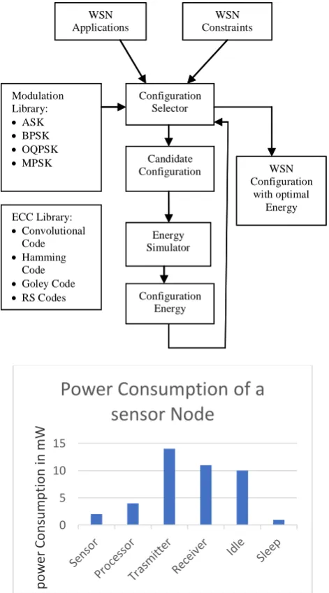
IV. SENSOR NODE ENERGY MODEL AND ENERGY ANALYSIS The factors on which energy consumption of a sensor node depends are Internodes distance(d), chosenBER, modulationtechniques, and ECCs[11].Fig. 2 shows the WSN design space exploration methodology for designing an energy-efficient networkwith various design parameters. The design space parameters are driven by WSN application and associated constraints. The deployment range is guided by specified application with the parameters such as area under surveillance, number of nodes to be deployed, network topology for efficiency and minimum power consumptionand the channel conditions.The minimum QoSto be maintained and Signal to noise ration (SNR)is the constraints to be maintained.Numerous optionsare provided bythe library to
the configuration selector for compression
techniques,channel coding techniques, modulation schemes and processor model.A particular configuration decided by the configuration selector based on above inputs. Energy consumption calculated by an energy simulator for chosen configuration.Feedback of energy consumption pattern helps the configuration to repeat the optimal energy isobtained. Library:
Convolutional Code Hamming
Code Goley Code RS Codes
guration Selector SN
Applications
N Constraints
Candidate Configuration
rgy Simulator Library:
ASK BPSK OQPSK MPSK
Configuration with optimal
Energy
[image:2.595.34.271.301.552.2]International Journal of Innovative Technology and Exploring Engineering (IJITEE) ISSN: 2278-3075, Volume-8 Issue-7, May, 2019
Fig. 4 The power consumption of a Sensor Node in various modes of operation
Figure 4 depicts the power consumption of various subsystems in a typical WSN node and modes of operation namely Transmit, receive, idle and sleep mode. [14],[15], [16]. From here, it is noted that communication subsystem (Transmit-Receive mode) consumes maximumpower as compared to other subsystems or modes of operation in the sensor node. For MICAz mote platform sensor node the energy consumed in Transmit mode is 25.4 mA, receive mode15.1 mA, idle mode 3.2 mA and sleep mode consumes 27 µA.
A. Radio Energy Model (Radio EM):
The components which contribute to the variation in energy consumption of a radio energy model are energy consumed in signal transmitting and energy consumed by radio circuit [14] [16].
On transmitting L bits, the radio energy per bit can be written as [12],
… (3)
where, iand Ticorrespond to power consumed in transceiver and mode duration and i = on, sp,trfortransceiver
on, sleep, and transmitmodes. Thesummation of signal transmit power and circuit power consumption _ is the power consumption in radio during ON mode.Thus, the radio energy consumption is
……. (4)
B. Transceiver Circuit Energy Model:
Total Circuit power consumption ( _ ) depends on power consumed in power amplifier (PA) power ( ) and other transceiver circuit elements power ( ) namely digital to analog converter (DAC, low pass and band pass filters (LPF and BPF), frequency synthesizer (FS) and low noise and intermediate frequency amplifiers (LNA and IFA).
_ = + ... (5)
= +2 +2 +2 + + + ………… (6)
C. Transmit Single Energy Model:
The transmitted power required for sending L bits is given by
………… (7)
Signal power required in the free space can be obtained with Friis transmission equation [13]
………… (8)
where, is the receiver power; and correspond to distance between transmitter and receiver, and wavelength of the transmitted signal. and are the
transmitter and receiverantenna gains and
exponent denotesthe path loss. The received power is
r uncoded NF ... (9)
Here, ed denotes the SNR ratio for transmitting uncoded data, denotes number of bits per modulation symbol, denotes bandwidth, noise spectral density is 0/2 for the AWGN channel, and receiver noise figureis .
D. Computation Energy Model(CompEM):
The total computation energy per bit is
…… (10)
where Eencis encoder and Edecis decoder computation energy. The final node energy per information bit for the coded system is the summation of and
E. Final node Energy Equation:
Ina coded system, the Energy of node per bit is the summation of radio energy and computation energy. It is denoted byEnode_codedand calculated by using Eq. (4), (6), (7) and (10)
0 5 10 15
po
w
er
C
o
ns
um
pt
io
n
in
mW
Power Consumption of a
sensor Node
ECC Library: Convolutional
Code Hamming
Code Goley Code RS CodesECC
Configuration SelectorConfi WSN
ApplicationsW
WSN ConstraintsWS
Candidate Configuration
Energy SimulatorEne Modulation
Library: ASK BPSK OQPSK MPSK
Modulation Configuration WSN
with optimal EnergyWSN
Configuration EnergyConfig ECC Library:
Convolutional Code Hamming
Code Goley Code RS Codes
Configuration Selector WSN
Applications
WSN Constraints
Candidate Configuration
Energy Simulator Modulation
Library: ASK BPSK OQPSK MPSK
WSN Configuration
with optimal Energy
[image:3.595.52.288.83.508.2]
... (11)
where, K is the number of message bits and N representstotal number of encoded bits.
V. SIMULATIONRESULTS:
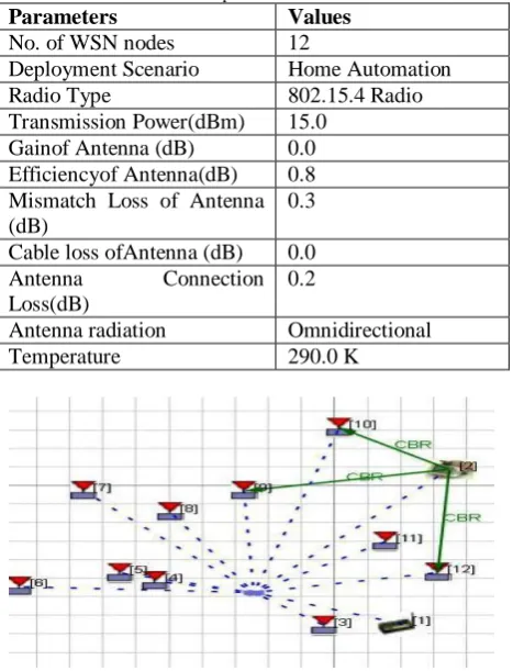
[image:4.595.327.528.56.162.2] [image:4.595.43.277.192.498.2]Three modulation schemes i.e. ASK, BPSK and OQPSK were evaluated in Qulanet network simulator as shown in table 2 and Fig. 5
Table 2. Simulation parameters
Parameters Values
No. of WSN nodes 12
Deployment Scenario Home Automation
Radio Type 802.15.4 Radio
Transmission Power(dBm) 15.0
Gainof Antenna (dB) 0.0
Efficiencyof Antenna(dB) 0.8 Mismatch Loss of Antenna (dB)
0.3
Cable loss ofAntenna (dB) 0.0
Antenna Connection
Loss(dB)
0.2
Antenna radiation Omnidirectional
Temperature 290.0 K
Fig. 5 WSN nodes in Home Automation Scenario of Qualnet Network Simulator
From Table 3, it is seen that the ASK is consuming the smallest power in all three modes as compared to BPSK & OQPSK (uncoded data transmission). But as we know that the Noise has a high effect on ASK modulated data packets therefore unwillingly, we have to leave the ASK from our choice for WSN and to choose the second smallest energy consumption modulation scheme i.e. OQPSK for WSNs.
Table 3. Simulation Results for Energy Consumed in 12 Sensor Nodes:
Exp . No.
Modulatio n Scheme
Transmi t Mode
Receiv
e Mode Sleep Idle Mode
Total Energ y (mJ) (mJ) (mJ)
Mod e (mJ)
(mJ)
1 ASK 0.0712 0.203 0
10.73
9 11.013
2 BPSK 0.3745 1.254 0
10.48
7 12.115
3 OQPSK 0.0725 0.215 0
10.73
6 11.023
Fig. 6 Total Energy Consumed (mJ) using ASK, BPSK & OQPSK Modulations
Fig. 7 Plot of differet modulation schemes ( ASK, BPSK and OQPSK) versus SNR
For error control codes with modulation schemes, the simulation is performed in MATLAB simulator. The obtained simulation results have been shown in table 3 and figure 5.
Table 4. MATLAB Simulation Results for RS (N=63) code with t=2 & t=4:
Distanc e (d)
BPS K
Node EnergyE1 per data bit(µJ) at t=2
Node EnergyE2 per data bit(µJ) at t=4
Node Energy saving (µJ) E3= E1 – E2
Node energy saving (%)= (E3/E1) X100
30 2 5.38 2.79 2.60 47%
60 2 5.41 2.81 2.60 48%
(max.)
90 2 5.42 2.85 2.57 47%
120 2 5.52 2.92 2.60 47%
150 2 5.54 3.20 2.34 42%
180 2 5.75 3.40 2.35 40%
[image:4.595.303.556.192.353.2]International Journal of Innovative Technology and Exploring Engineering (IJITEE) ISSN: 2278-3075, Volume-8 Issue-7, May, 2019
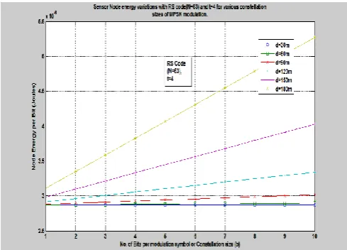
Fig. 8 Sensor Node energy variations with respect to distances at t =4.
Fig. 9 Sensor Node energy variations with respect to distances at t =2.
The Figs. 8 and 9 show WSN node energy variations using RS codes with BPSK at N=63 and error correcting capability (t=4 and t=2) for various distances respectively
VI. CONCLUSION:
A methodology for the energy consumption of sensor nodes has been discussed in this paperand evaluation is done on the basis of various ECCs. A home automation scenario is considered for evaluation. The simulation results show that in sensor node with Reed-Solomon codes and BPSK modulation consume the optimal energy in certain operating conditions. We find at distance (d) =60m an optimal ECC-modulation pair RS (N=63) code with t=4 & BPSK modulations schemes gives 48% energy savings.
REFERENCES
1. S. Chouhan, R. Bose, and M. Balakrishnan, “A framework for energy consumption-based design space exploration for wireless sensor nodes,”IEEE Trans. Comput-Aided Design Integr. Circuits Syst., vol. 28, no. 7, pp 1017-1024, ,July 2009.
2. S. Cui, A. J. Goldsmith, and A. Bahai, “Energy-constrained modulation optimization,” IEEE Trans. Wireless Commun., vol. 4, no. 7, pp. 2349-2360, Sept. 2005.
3. A. Y. Wang, S. H. Cho, C. Sodini, and A. Chandrakasan, “Energy efficient modulation and MAC for asymmetric RF microsensor systems,” in Proc.Int.Symp. Low Power Electronics Design,2001, pp. 106-111,
4. H. Sharma and V. K. Sachan, “Optimization of energy efficiency in Wireless Sensor Networks using Error control codes,” Students Conference on Engineering and Systems (SCES-2012), MNNIT, Allahabad, 2012,
5. G. A. AL-Suhail, K.W. Louis, and T. Y. Abdallah, “Energy Efficiency Analysis of Adaptive Error Correction in Wireless Sensor Networks,”IJCSI International Journal of Computer Science Issues,vol. 9, issue 4, no 2, July 2012, pp 79-84.
6. H. Sharma and V. K. Sachan, “Performance analysis of modulation Techniques for Energy Efficient Wireless Sensor Networks” International Conference on Communication and Electronics (ICCE-2012), held at KIET, Ghaziabad,U.P., Oct. 2012, India, proceedings vol.1, pp.79.
7. I.F. Akyildiz, W. Su, Y. Sankarasubramaniam and E. Cayirci, “A Surveyon Sensor Networks,”IEEE Communications Magazine, 2002. 8. M. A. Hannan, S. M. Abbas, S. A. Samad and A. Hussain, “Modulation
Techniques forBiomedical Implanted Devices and TheirChallenges”,SensorsJournal, 2012, vol.12, pp. 297-319. 9. G. Balakrishnan, M. Yang, Y. Jiang, and Y. Kim, “Performance analysis
of error control codes for wireless sensor networks,”In Proc. Int. Conf. Inform. Technol., 2007, pp. 876-879.
10. B. Sklar, Digital Communications Fundamentals and Applications,2nd Ed., Pearson Education Inc., New Jersey, USA, 2012.
11. J. H. Kleinschmidt and W.D. C. Borelli, “Adaptive Error Control Using ARQ and BCH Codes in Sensor Networks Using Coverage Area Information,”IEEE 20th International Symposium on Personal, Indoor and Mobile Radio Communications, 2009.
12. J. G. Proakis, Digital Communications, 4th ed. New York, McGraw-Hill. 2014.
13. S. Lin and D. J. Castell, Error Control Coding – Fundamentals & Applications, 2nd ed., Pearson Education Inc., New Jersey, USA, 2004. 14. H. Anna,Wireless Sensor Network Design, John Willey & Sons
Publication Publications, 2003.
15. H. Carl and A. Willing, Protocols and Architecture for Wireless Sensor Networks, John Willey & Sons Publication, 2005.
16. Moteview 2.0 User Manual & Mica2 Datasheets.
17. V. Pushpa, H. Ranganathan and M. Palanivelan, “BER Analysis of BPSK for Block Codes and Convolution Codes Over AWGN Channel”, Int. Journal of Pure and Applied Mathematics, vol.114,no. 11, 2017, pp 221-230.
18. N. A. Alrajeh, U. Marwat, B. Shamsand S. S. H. Shah,
“Error-Correcting Codes in Wireless Sensor Networks:An Energy Perspective”, Journal of Applied Mathematics & Information Sciences, vol. 9, no. 2, 2015, pp 809-818.
AUTHORSPROFILE
Bhavnesh Jaintreceived her B.E. degree in Electronics and Telecommunication Engineering from Government College of Engineering, Jabalpur, M.P India and M.E.
degree in Electrical Engineering from Jabalpur
Engineering College, Rajiv Gandhi Proudhyogiki Vishwavidyalaya Bhopal, M.P., India. During her M.E., she has completed a dissertation in the area of Fuzzy logic. She has started her carrier as Lecturer of Electronics and Communication at BBITRC, Jhangribad affiliated to UPTU. She has also worked as Assistant Professor at
ABES Engineering College, Ghaziabad. Presently, she is Assistance
Professor in the Department of Electrical Engineering at Delhi Technological University, Delhi, India. She has taught different UG and PG Level courses in different institutions particularly at the Department of Electrical Engineering. She has guided four M.Tech. students in the area of
the control system, the Internet on Things. She is a member of different
statutory committees of the university. She is also the life member of professional societies Indian Unit for Pattern Recognition and Artificial Intelligence. Also, a member of the IEEE.
Her research interests include wireless sensor network, Embedded System IOT, Control System.
Dr S. Indu received B.Tech. (Electrical Engineering)
[image:5.595.32.277.49.225.2]There are 6 PhD students pursuing a PhD under her. Under her guidance 2 candidates completed PhD successfully.She is a Life Member of ISTE, IETE and IUPRAI. and senior member of IEEE.
Her area of research interest is Computer Vision, Sensor Networks and Image Processing. She has published one book “Smart Camera Networks” and one Book Chapter “Video Surveillance” published by INTECH, UK. She has published around 70 publications in international journals, National and International conferences. She has completed 3 Sponsored projects as Principal Investigator, sponsored by Naval Research Board and Department of Science and Technology.
.
![Fig. 2 Framework for finding optimal ECC-Modulation[4]](https://thumb-us.123doks.com/thumbv2/123dok_us/8204915.261882/2.595.34.271.301.552/fig-framework-for-finding-optimal-ecc-modulation.webp)