This is a repository copy of Improved Plane-Wave Illumination for TLM Method. White Rose Research Online URL for this paper:
http://eprints.whiterose.ac.uk/126780/ Version: Accepted Version
Article:
Porter, S. J. and Dawson, J. F. orcid.org/0000-0003-4537-9977 (1993) Improved Plane-Wave Illumination for TLM Method. Electronics Letters. pp. 1663-1664. ISSN 0013-5194
https://doi.org/10.1049/el:19931107
[email protected] https://eprints.whiterose.ac.uk/
Reuse
["licenses_typename_other" not defined]
Takedown
If you consider content in White Rose Research Online to be in breach of UK law, please notify us by
Improved Plane-Wave Illumination for the TLM
Method
S.J. Porter and J.F. Dawson
Department of Electronics, University of York,
Heslington, York, YO1 5DD, UK
Indexing Terms
Transmission line matrix, TLM, Modelling, Electromagnetic waves, Huygen’s sur-face
Abstract
An efficient solution to the problems associated with plane wave illumination of a scattering body in a TLM mesh is presented. The solution is equivalent to a partial implementation of the Huygen’s surface [1] used in the Time-Domain Finite Difference (TDFD) method, but, additionally, accounts for dispersion effects.
Introduction
The Transmission Line Matrix (TLM) method of numerical electromagnetic analysis using the symmetrical condensed node is well known [2]. It has been widely used to determine scattering from structures under plane wave illumination. However the problems of obtaining an accurate plane wave are not well reported. Here we will address these problems and provide a simple and efficient solution.
When a plane wave is excited in a finite TLM mesh with matched1 boundaries,
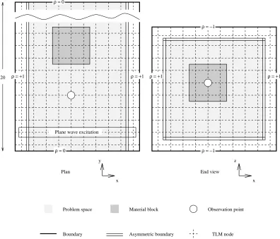
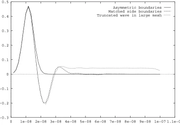
the sudden truncation of the mesh causes a second wavefront to be generated at each boundary. This is due mainly to the physical truncation of the wavefront at the boundaries and to a lesser extent to the fact that the boundary does not represent a true radiation boundary condition. In order to demonstrate this a simple Gaussian plane wave was excited in a TLM mesh, with a 10x10 node cross section (Fig. 1), and the field observed for three scenarios (Fig. 2):
1. with the wave propagating in the mesh with asymmetric boundaries as de-scribed below – the Gaussian profile is preserved;
2. with no asymmetric boundaries and matched terminations at the edges of the mesh – a considerable negative excursion occurs after the initial Gaussian pulse due to the truncation of the wavefront at the boundaries of the problem;
1The transmission lines at the outer surface being terminated in a matched load.
Porter, S. & Dawson, J. , "Improved plane-wave illumination for TLM method" , Electronics Letters , vol. 29, no. 18 , 1663-1664 , 2 Sept. , 1993 , DOI: 10.1049/el:19931107
3. with the same 10x10 node plane wave as in 2) in a larger mesh (60x60) – a similar time response occurred showing that the negative excursion is mainly due to the truncation of the wave rather than failure of the boundary in some way.
The problem of plane wave illumination is often overcome using problem bound-aries which have a +1 reflection coefficient (magnetic walls) at the edge of the wave parallel to the electric field and –1 reflecting boundaries perpendicular to the electric field. This produces an ideal waveguide in which a plane wave can propagate. How-ever these reflecting walls serve to return waves scattered by the illuminated object to the observation point which interfere with the observation of the direct scattered waves. In order to avoid this the problem space must be made large enough that reflections from the boundaries do not reach the observation point in the time span of the simulation. However this results in an excessively large problem space and may not be possible where a large number of iterations are required.
The implementation of asymmetric boundaries, equivalent to a partial Huygen’s surface, proposed here provides an efficient solution to the problems outlined above.
20 ρ = +1 ρ = +1
Plane wave excitation
ρ = −1
ρ = +1 ρ = +1
ρ = −1
x Plan
y z
x End view
TLM node Observation point
Asymmetric boundary Material block
Boundary Problem space
ρ = 0
[image:3.595.125.521.315.654.2]ρ = 0
Figure 1: Arrangement of asymmetric boundaries within the TLM mesh.
Implementation
TLM mesh is terminated with –1 reflection coefficient boundaries on the faces per-pendicular to the electric field of the plane wave, +1 reflection boundaries parallel to the electric field, and matched boundaries on the remaining two faces. Asymmet-ric boundaries are constructed, as a tube, parallel to the direction of propagation of the plane wave, one mesh unit inside the TLM mesh. The reflection coefficient of the inside faces of the asymmetric boundaries is set to zero (matched) as is the transmission coefficient. This means that the problem space appears to have matched boundaries on all sides for the scattered fields. Also no energy from the inner problem space can reach the outer region between the asymmetric boundaries and the sides of the TLM mesh. The outer faces of the asymmetric boundaries have reflection coefficients identical to the outer boundary which they face and a unity transmission coefficient. Thus a (plane) wave can propagate in the waveguide formed by the asymmetric boundaries and outer surface of the mesh undisturbed by any waves from within the problem space. However if a plane wave is excited across the entire cross section of the TLM mesh (as in Fig. 1) the parts of the wave propagating in the problem space and the outer layer are in time phase and will remain so regardless of any dispersion in the mesh. The energy transmitted from the outer layer to the problem space provides the necessary continuity so that the wave in the problem space is not truncated and thus no spurious wavefronts are generated.
Therefore, by the use of asymmetric boundaries we have achieved propagating conditions for the exciting plane wave as if we had used +/–1 problem space bound-aries to create a waveguide capable of sustaining the wave, whilst for scattered fields the problem space has matched boundaries. The method can be shown to be equivalent to a partial implementation of a Huygen’s surface as used in the TDFD method.
-0.3 -0.2 -0.1 0 0.1 0.2 0.3 0.4 0.5
0 1e-08 2e-08 3e-08 4e-08 5e-08 6e-08 7e-08 8e-08 9e-08 1e-07 1.1e-07 Asymmetric boundaries
[image:4.595.156.524.461.716.2]Matched side boundaries Truncated wave in large mesh
Results
Fig. 2 shows the time history of the fields at the observation point in Fig. 1 for the cases where asymmetric boundaries (partial Huygen’s surface) are used, where matched boundaries are used, and where a truncated plane wave in a larger problem space have been used. The Gaussian pulse shape is seen for the first case but in the second two the truncation of the plane wave produces additional wavefronts from the ends of the wave which distort the waveform at the observation point. The case for +/–1 boundaries corresponds exactly to the case with asymmetric boundaries here as there are no scattered fields.
-0.2 -0.1 0 0.1 0.2 0.3 0.4 0.5
0 1e-08 2e-08 3e-08 4e-08 5e-08 6e-08 7e-08 8e-08 9e-08 1e-07 1.1e-07
Ez Amplitude
Time (s) incident wave
scattered wave
Asymmetric boundaries +/-1 side boundaries Matched side boundaries +/-1 sides: Large space
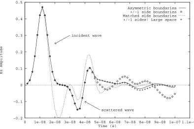
Figure 3: Gaussian pulse plane wave in mesh with scattering object.
Fig. 3 show the time history at the observation point with the scattering object (Fig. 1) present. It can be seen that the use of the partial Huygen’s surface gives results (solid line) which correspond very closely to the ideal case (+ points) with +/–1 boundaries used with a very large (60x20x60) mesh size but this is achieved with a small (10x20x10) mesh size. The large mesh size ensures that the reflections from the boundaries do not reach the observation point within the observed time span. For the small mesh size, +/–1 boundaries result (diamonds) in multiple reflections which distort the observation of the scattered field as does the additional wavefront if matched boundaries are used (broken line).
Conclusions
(equiva-compensation for any dispersion in the mesh is achieved. This also means that the method is suitable for problems using a graded mesh without further modification.
References
[1] D.E. Merewether, R. Fisher, and F.W. Smith. On implementing a numeric Huygen’s source scheme in a finite difference program to illuminate scattering bodies. IEEE Transactions on Nuclear Science, pages 1829–1833, 1980.