UNIVERSITI TEKNIKAL MALAYSIA MELAKA
FACULTY OF ELECTRICAL ENGINEERING
FINAL YEAR PROJECT 2
REPORT
Design an Intelligent Controller for Depth Control of ROV using
Micro-box 2000/2000C
Name : Lee Dai Cong
Course : 4 BEKM 2
Year : 2014
“ I hereby declare that I have read through this report entitle “Design an Intelligent
Controller for Depth Control of ROV using Micro-box 2000/2000C” and found that it has
comply the partial fulfillment for awarding the degree of Bachelor of Mechatronics
Engineering with Honors”
Signature :...
Supervisor :...
LEE DAI CONG
A report submitted in partial fulfillment of the requirements for the degree of Bachelor of Mechatronics Engineering with Honors
Faculty of Electrical Engineering
UNIVERSITI TEKNIKAL MALAYSIA MELAKA
I declare that this report entitle “Design an Intelligent Controller for Depth Control of ROV using Micro-box 2000/2000C” is the result of my own research except as cited in the references. The
report has not been accepted for any degree and is not concurrently submitted in candidature of any other degree.
Signature :...
Name :...
Dedication
To my beloved father and mother
Acknowledgement
In the process of doing this final year project, I was helped by many peoples. They
are all being helpful and contributed their time to me without second thought. I would like
to take this opportunity to show my sincere appreciation to Pn. Fadilah binti Abdul Azis for
accepting me as her final year project student. She always correct my mistakes and teach me
whenever she can even during her rest time.
En. Mohd Shahrieel Mohd Aras had always been helpful in giving me suggestion
while I doing my project, he never hesitate to teach me all he can and share his experience
to me. His contribution to my final year project should always be remember.
I would also like to thanks Universiti Teknikal Malaysia Melaka (UTeM) for provide
us all the needed facilities and resources such as online IEEE journal and library. This is
very useful especially when I need to do my literature review.
Last but not least, I would like to thanks all my fellow friends who helped me while
I doing my final year project. It was them who always reminded me for what should I do and
Abstrak
Projek ini adalah mengenai mencipta dan membina pengawal pintar kawalan
kedalaman ROV menggunakan Micro-Box 2000/2000C. Terdapat beberapa masalah ROV
masa kini, yang paling penting ialah masalah kebocoran air. Kebocoran air disebabkan oleh
haus dan kesan air mata apabila seseorang membuka badan kapal tekanan. Masa selepas
masa, badan kapal tekanan longgar dan akan membolehkan air untuk pergi ke dalam badan
kapal tekanan dan merosakkan bahagian elektronik di dalamnya. Masalah lain adalah bateri
ROV senang dihabiskan menyebabkan terhad masa untuk menguji dan menggunakan ROV.
Masalah perparitan semasa akan menyebabkan pengguna perlu kerap membuka badan kapal
tekanan untuk tukar bateri. Pengawal ‘fuzzy logic’ adalah sangat baru dalam bidang
pengawal dan tidak mempunyai panduan yang formal untuk tuning dan menyebabkan masa
berharga dibazir. Oleh itu, kajian mengenai kesan mengalih fungsi keahlian sifar akan
dilakukan sebagai panduan umum untuk tuning pengawal ‘fuzzy logic’ untuk kerja-kerja
masa depan. Untuk menyelesaikan masalah ini, ROV Simulator yang tidak berfungsi bawah
air akan dibina. Kawalan kedalaman akan menggunakan pengawal ‘fuzzy logic’ dengan
Micro-Box 2000/2000C. Pengawal ‘fuzzy logic’ akan digunakan untuk mengalihkan fungsi
keahlian sifar supaya kesan pelarasan boleh dikaji dan diguna sebagai satu garis panduan
umum tuning pengawal ‘fuzzy logic’. Hasilnya akan dianalisis untuk menentukan hasil
projek. Hasilnya menunjukkan bahawa pengawal ‘fuzzy logic’ boleh digunakan simulator
ROV itu. Hasil projek ini menunjukkan dengan mengalihkan fungsi keahlian sifar pengawal
Abstract
This project is about the design and develop of intelligent controller of ROV depth
control using Micro 2000/2000C. There are some problem while developing a ROV and the
most significant is the water leakage problem. The water leakage problem is highly cause by
the wear and tear effect whenever someone open up the pressure hull. Time after time, the
pressure hull will loose and enable the water to go into the pressure hull and damage the
electronics part in it. The other major problem with a ROV is the thruster can easily drain up
current from the battery source or power bank and this will limited the time to test and use
the ROV. The current drainage problem will also cause the user to have the need to change
the power source frequently by open up the pressure hull. The fuzzy logic controller is very
new in the field of controller and thus do not have a proper guide to fine tune it and cause
the tuning of it to be highly time costing. Therefore, a study on the effect of shifting the zero
membership function will act as a general guide to further tune the fuzzy logic controller for
future works. To solve the problem stated, a ROV Simulator which will not work underwater
will be develop to test the control system. To build a ROV simulator, there will be need of
using aluminum trial, thrusters, drivers, interface connector, and also controller. The depth
control will be implement using Micro 2000/2000C with fuzzy logic controller. The tuned
fuzzy logic controller will be adjust by shifting the zero membership function so that the
effect of the adjustment can be study and act as a general guideline while tuning fuzzy logic
controller. The result was being tabulated, plotted and analyze to determine the outcome of
the project. The result shows that the fuzzy logic controller can be implement to the ROV
simulator. The result of this project shows that, by shifting the zero membership function of
the fuzzy logic controller the performance of the fuzzy logic controller generally decrease
Table of Content
Chapter Title Page
Acknowledgement
Abstrak iii
Abstract iv
Table of Content v
List of Figures viii
List of Table xi
Introduction 1
1.1 Overview 1
1.2 Motivation 1
1.3 Problem Statement 3
1.4 Objective 4
1.5 Project scope and limitation 4
Literature Review 5
2.1 Introduction 5
2.2 Related Previous Works 5
2.3 Summary of Literature Review 13
Methodology 14
3.1 ROV Simulator 16
3.1.1 Pressure Sensor 17
1
2
3
3.1.2 Driver 17
3.1.3 Thruster with Propeller 18
3.2 Micro 2000/2000C 19
3.3 Fuzzy Logic Controller 19
3.4 Experiment 23
3.4.1 Experiment 1: ROV Simulator 23
3.4.2 Experiment 2: Pressure sensor 24 3.4.3 Experiment 3: Fuzzy Logic Controller simulation using
MATLAB 27
3.4.4 Experiment 4: Effect of zero output membership function of
transfer function Fuzzy Logic Controller using MATLAB 31
3.4.5 Experiment 5: Effect of zero output membership function of
real-time Fuzzy Logic Controller using Micro 2000/2000C with ROV
Simulator 38
Results 43
4.1 Overview 43
4.2 Experiment 1: ROV Simulator 43
4.3 Experiment 2: Pressure sensor 45
4.4 Experiment 3: Fuzzy Logic Controller simulation using MATLAB 49
4.5 Experiment 4: Effect of zero output membership function of transfer
function Fuzzy Logic Controller using MATLAB 51
4.6 Experiment 5: Effect of zero output membership function of real-time
Fuzzy Logic Controller using Micro 2000/2000C with ROV Simulator 53
4.7 Summary of experiments 56
Conclusion and recommendation 57
5.1 Conclusion 57
5.2 Recommendation 58
References 59
Appendices 61
Appendix A 61
List of Figures
Figure Title Page
1.1 1.2 2.1 2.2 2.3 2.4 2.5 3.1 3.2 3.3 3.4 3.5 3.6 3.7 3.8 3.9 3.10 3.11 3.12 3.13 3.14 3.15 3.16 3.17 3.18 3.19
ROV post mortem investigation for Macondo well
ROV deployment for MH370 black box searching operation
PD and Fuzzy Logic Controller Response of Depth
Response of Gain-Scheduled Reduced Order Output Feedback
Controller
Adaptive Plus Disturbance Observer response
Fuzzy Logic Controller Response
C.C.Lee System Step Response Graph
K-Chart of Vehicle
Project Flow Chart
ROV Simulator
Layout of ROV Simulator
MPX4250GP Pressure Sensor
Thruster Driver
Thruster PROTEUS Circuit Simulation
Micro 2000/2000C
Fuzzy Logic controller Simulink Block Diagram
FIS Editor
Membership Function Editor
Rule Editor
Flow chart for experiment 1
Flow chart for experiment 2
Multimeter
Pressure sensor regulating circuit
Step-down voltage regulator
Pressure Sensor
Experiment set up for pressure sensor experiment
3.20 3.21 3.22 3.23 3.24 3.25 3.26 3.27 3.28 3.29 3.30 3.31 3.32 3.33 3.34 3.35 3.36 3.37 3.38 3.39 3.40 3.41 3.42 3.43 3.44 3.45 3.46 3.47 3.48 4.1 4.2 4.3 4.4
Flow chart for experiment 3
Simulink Block Diagram
Output membership function
Input membership function (error)
Input membership function (Integral of error)
Scope parameters setting
Initial output response
Flow chart for experiment 4
MATLAB command
Original output membership function "center"
Original graph of depth vs time for "center"
Output membership function "left"
Graph of depth vs time for "left"
Output membership function "Right"
Graph of depth vs time for "right"
Output membership function "big"
Graph of depth vs time for "big"
Output membership function "small"
Graph of depth vs time for "small"
Flow chart for experiment 5
Micro 2000/2000C
Thruster driver
Mini air compressor
Thruster
Pressure sensor and its circuit
Micro connector arrangement
Setup for experiment 5
Block diagram for real-time control
Voltage to meter conversion subsystem
Measurement of components
Installation of components
ROV Simulator
Graph of voltage vs pressure for pressure sensor
4.5
4.6
4.7
4.8
4.9
4.10
Graph of Ideal voltage compare to real voltage
Tuned output membership function
Graph of depth vs time for tuned output membership function
First verification of subsystem
Second verification of subsystem
Third verification of subsystem
46
50
50
53
53
List of Table
Table Title Page
2.1 2.2 2.3 3.1 3.2 4.1 4.2 4.3 4.4 4.5 4.6 4.7 4.8 4.9
C.C.Lee Rules Table
Rule Based Table
Summary of Controller
Fuzzy logic controller rules
Micro 2000/2000C connection with sensor and thruster
Table of pressure to depth vs voltage
Table of Pressure sensor error
Simulation result for effect of shifting of zero membership function
Table of simulation performance of shifting of zero membership
function
Table of verification of subsystem
Table of average rise time and settling time
Table of average percent overshoot and steady state error
Table of Real-time result for effect of shifting of zero membership
function
Table of real-time performance of shifting of zero membership
1. Chapter 1
Introduction
1.1 Overview
ROV is an underwater unmanned vehicle where main purpose is to observe underwater
condition and perform underwater operation where divers cannot reach. ROVs are highly
implement in offshore underwater operation by oil and gas company and scientist whose
main purpose is to do research and exploration of underwater knowledge. The final year
project with the title of design an intelligence controller for depth control of ROV using
Micro 2000/2000c thou is mainly about the control system for ROV depth control.
1.2 Motivation
The main motive to choose the title of ‘design an intelligent controller for depth control
of ROV using Micro 2000/2000c’ out of all other final year project is that ROV is highly
interesting. ROV is highly use for offshore operation including drilling, observation, and
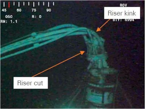
others. The famous Deepwater Horizon Macondo well uses ROV to seal the leaking well
and also post mortem investigation was done by ROV to prevent similar tragedy to happen
in the future. The accident had already affected almost the whole Gulf of Mexico ecosystem
and without the ROV, the damage may be even worse than anyone can expected. The post
mortem investigation of the ROV is as shown as figure 1.1 [8]. ROV also being uses for
possible for the search of black box to be carry out. The weather of the deep water sea is
highly vicious and sending in human for the operation is consider unrealistic. The assembly
of the ROV for black box searching can refer to figure 1.2 [9]. Therefore, the importance of
ROV is highly underrated as it never receive high public appreciation. To develop the fuzzy
logic controller is consider a new approach for control system, and because of it, there are
no exact ways to tune it nicely. Therefore, develop a simple overview on how will output
[image:17.595.178.433.252.442.2]membership function affect the result matters.
Figure 1.1- ROV post mortem investigation for Macondo well
[image:17.595.130.479.515.700.2]1.3 Problem Statement
There are many problem encounter by remotely operated underwater vehicle and one
of the most important problem is leaking. Because of the reason that remotely operated
underwater vehicle is electronically controlled vehicle, leaking of water into the body of it
means malfunction of it.
Other than that, because of the reason that the thruster consume a lot of current, normal
battery can only last around 5 minutes underwater. When the battery run out of current, the
operator will have to take out the ROV and replace its battery which cause another problem
where wear and tear may happen during opening the body of ROV. Because of the limited
time of the ROV in the water, some part of the control system may never have the chance to
really be tested. It is highly undesirable especially for testing of control system purpose.
Therefore, a ROV simulator which will not be place underwater should be made in order to
test the control system designed and fine-tuned it.
The conventional control system for remotely operated underwater vehicle which is
PID controller cannot function well when it is in the underwater environment. This is due to
conventional PID controller do not suitable to work with non-linear environment. Because
it is crucial for remotely operated underwater vehicle to not contact with the seabed which
might cause damage to the remotely operated underwater vehicle, the control system of it
should have minimum overshoot and it can hardly be done by conventional PID controller.
Thus, intelligence control system such as fuzzy logic controller is needed in order to solve
this problem.
Last but not least, fuzzy logic controller is consider new and there are no standards
way to tune it. Trial an error is the common approach to do this and this often results in a
great waste of time. Therefore, a simple overview of how zero output membership function
1.4 Objective
The objectives of this final year project is to
1. Design and develop an intelligence controller for real-time ROV depth control.
2. Design and develop a ROV simulator in order to do testing, analysis of rise time,
settling time, percent overshoot, and steady state error, and simulation of the fuzzy
logic control system.
3. Analyze the effect of adjustment for output zero membership function by simulation
and Micro 2000/2000C real-time control.
1.5 Project scope and limitation
This project will be carry out in a controlled environment where the disturbance will
be assume to zero. To carry it out in a controlled environment, a ROV simulator will be built
for this project to mimic the real life operation of ROV. This ROV simulator was built mainly
to overcome issue where it is troublesome to carry out the experiment in water. Since the
project is about depth control, only vertical up and down movement will be consider in the
project. The project is mainly about control system. Thus, the final year report will only brief
thru any other information other than control system related content for ROV. This project
will implement the intelligence control system by using Micro 2000/2000c only. Because of
the limitation where Micro 2000/2000c cannot be borrow out of CIA Lab, FKE. The
experiment will be carry out in Lab CIA only. The experiment will be carry out for depth of
3 meters only as the controller is not robust enough to carry out experiment at different
voltages, this is highly due to the reason that a robust fuzzy logic controller will require many
2. Chapter 2
Literature Review
2.1 Introduction
This topic will review related topic of ROV depth control. The topic which need to be
review will be mainly about the performance of certain controller’s works for ROV. The
reason of certain controller is suitable for ROV and certain controller isn’t will be study thru
this chapter. Journal of implementation for selected controller will also be review and study
in this chapter to help enhanced the knowledge which associated with the intelligent
controller.
2.2 Related Previous Works
According to journal [1], to derive a system equation is to derive a general non-linear
model that can be adopt by remotely operate vehicle to calculate its velocity and kinematic.
According to Newtonian or Lagrangian formalism, this derivation consider the remotely
operated vehicle as a six degree of freedom rigid body. The depth control are divided into
two different control method as discussed in this journal. But both method main concern is
to drastically limit the overshoot of the controller to a depth set-point change, while keep the
response time at a reasonably range. The reason for this is to assure the vehicle’s safety while
working near water-bottom and to prevent cable stresses for remotely operated vehicles.
controller introduce is a continuous input smoother (CIS) controller. This controller can
pre-filter the input signal to prevent sudden change that causes overshoot. This pre-filter is effective
but the disadvantage is that it have to be tuned off-line and different tuning suit different
working conditions. The second controller as to solve the problem faced by CIS controller,
Fuzzy-PID controller is introduced in the journal. As of the journal, discrete fuzzy smoother
(DFS) is chosen and the idea behind is that the vehicle working online can suit itself to
system behavior. The DFS drive the system with a sequence of steps which can reduce the
overshoot while still achieving a better response time as compare to CIS control system. [1]
According to journal [2], Proportional Integral Derivative (PID) controller is not
suitable for underwater unmanned vehicle as underwater condition exhibits highly
non-linear characteristic but PID controller can only process non-linearized characteristic best. The
journal also shows that without the need of formal mathematical model, rule based fuzzy
logic controller is suitable to work with non-linear dynamics. It also show that the equation
of motion as of for an underwater unmanned vehicle named nonlinear underwater vehicles
dynamic motion is [2]:
Mv̇ + C(v)v + D(v)v + g(η) = B(v)u (2.1)
Where,
M = 6 x 6 inertia matrix including hydrodynamic added mass
C(v) = matrix of the Coriolis and centripetal forces
D(v) = Hydrodynamic damping matrix
g(η) = Vector of restoring forces and moments
This journal contain experiments base on conventional PID controller and Fuzzy logic
controller. The transfer function used is:
u(t) e(t)=
Kds2+ K
ps + Ki
s (2.2)
Where,
u(t)= output
e(t)= error
Kd= derivative gain
Kp= proportional gain
Ki= integral gain
The proportional gain can reduce rise time and steady state error, integral gain to
eliminate steady state error but mess up the transient respond, and derivative gain to stabilize
the system by reduce overshoot while improve the transient response. For the fuzzy logic
part thou, uses error and rate of change of error to decide the unmanned underwater vehicle
action. According to figure 2.1, the experiments shows that the fuzzy logic controller work
better than PID controller as its rise time is the shortest while both have no overshoot. PID
controller thou have minor steady state error while fuzzy logic controller have no steady
[image:22.595.189.421.565.738.2]state error at all. [2]
According to journal [3], to design a control system for unmanned underwater vehicle
will need to determine the non-linear dynamic equation first. After determined them,
linearization of the system equation will be perform for a finite range of set points. According
to the linearized equation, a controller will be design to meet the equation requirements.
Interpolation of the controller according to vehicle’s speed will be perform and thus born the
gain-scheduled controller. Lastly, the gain-schedule controller will be implement on the
non-linear plant. Because of the interpolation is based on non-linearize system modelling equation
but implement on non-linear plant, the result at figure 2.2 shows that there are still overshoot
[image:23.595.95.519.299.520.2]happening for gain-scheduled controller. [3]
Figure 2.2- Response of Gain-Scheduled Reduced Order Output Feedback Controller[3]
According to journal [4]. The journal introduce adaptive plus disturbance observer
controller which make self-adjusting on position control be possible for ROV to happen.
This journal also introduce neural-network controller as one of the control approach to
control the ROV. It is stated that neural-network controller is highly suitable for non-linear
control approach as of what happen to ROV operating condition. But, to test the control
system will require real-life experiment to be done and no software simulation can replace
it because there is no mathematical characterization exist. Fuzzy logic controller according
approximation of non-linear mapping. But to determine the membership function and its
linguistic rules is time consuming and require experimental data. Adaptive controller which
will change the controller’s gain according to the disturbance but there is limitation where
the dynamic changing speed is too fast for it to control. The result as shown as figure 2.3
[image:24.595.98.518.213.346.2]shows that the controller have overshoot issue and minor fluctuation of depth. [4]
Figure 2.3 - Adaptive Plus Disturbance Observer response [4]
According to [5], it is stated that fuzzy like PD controller will need structures,
rule-base, cause and effect membership function, inference mechanism, defuzzification strategy,
and too the way to optimize the input and output scaling factors. The journal stated that the
use of Takagi–Sugeno fuzzy system is implemented in the system and that singleton output
can still perform well and do not consume too much times. Min and operation is used for the
inference mechanism of the fuzzy like PD controller for this journal. Weight average
defuzzification method is also being implemented in the system. The fuzzy-like PD
controller is than being tested in a lake and shows the result that this control system can
perform very well and stable in the lake. The ROV can stay at its desired depth with
controlled amount of fluctuations of depth and a little bit of overshoot according to the
journal. Showing from figure 2.4, it can be show that there are fluctuation but no overshoot
![Figure 2.1PD and Fuzzy Logic Controller Response of Depth [2]](https://thumb-us.123doks.com/thumbv2/123dok_us/137733.14877/22.595.189.421.565.738/figure-pd-fuzzy-logic-controller-response-depth.webp)
![Figure 2.2- Response of Gain-Scheduled Reduced Order Output Feedback Controller[3]](https://thumb-us.123doks.com/thumbv2/123dok_us/137733.14877/23.595.95.519.299.520/figure-response-scheduled-reduced-order-output-feedback-controller.webp)
![Figure 2.3 - Adaptive Plus Disturbance Observer response [4]](https://thumb-us.123doks.com/thumbv2/123dok_us/137733.14877/24.595.98.518.213.346/figure-adaptive-disturbance-observer-response.webp)
