Website: www.ijetae.com (ISSN 2250-2459, Volume 2, Issue 11, November 2012)
Speed Control of an Intelligent Tank Using PID Controller
(Modelling, Simulation, Architecture Design and GUI Implementation)
Atif Ali Khan
1, Adnan I. Elberjaoui Yakzan
2, Oumair Naseer
3, Bilal S. Chehab
4 1,2 School of Engineering, University of Warwick, Coventry, UK,3 Department of Computer Science, University of Warwick, Coventry, UK, 4
Hariri Canadian University, Lebanon
Abstract — The need for robots to work on their own is becoming highly on demand. In this paper, speed control of an intelligent tank is presented. This is the extension of work carried out by the authors for designing an intelligent battle tank. An intelligent tank that is capable of being in a room, with no prior mapping, can understand and draw its trajectory to an intended purpose. Using a set of light detecting resistors (LDR), and IR sensors, a fuzzy controlled brain maneuvers around obstacles and reaches a specified destination avoiding collision with the obstacles coming in its path. Both the controllers work simultaneously to transform an ordinary tank into an intelligent battle tank which can take decisions on its own under any environment and in any circumstances. This paper presents the design, simulation and implementation of the speed control of the tank. Control systems can be analyzed easily and in depth with software tools like Matlab. DC motor modeling is analyzed with control techniques of step response, impulse response and bode plots by using Matlab Simulink environment. Processing with the real time hardware is becoming a big challenge. By the advance control analysis in simulation environment, high-tech problems can be solved with ease and in little time saving the hardware cost and hardware assembling overheads. Test results show that the controller works very well to control the speed of the tank.
Keywords - DC Motor; GUI; Simulink; PID, Speed Control.
I. INTRODUCTION
Robots are mechanical bodies capable of moving in an environment with some degree autonomy. Different types of sensors like (IR, LASER, ultrasonic, etc.) are deployed to understand the capability of detecting obstacles and measuring the distance to walls and other parameters to serve several indoors applications. One major part of such applications involves control problems. In the eye of robotics, the controller is the brain of the robot's movements. It's usually a computer of some type which is used to store information about the robot and the work environment and to store and execute programs which operate the robot. The control system contains programs, data algorithms, logic analysis and various other processing activities which enable the robot to perform.
[image:1.595.353.495.304.429.2]In the previous achievements [1], researchers tend to give two fuzzy controllers, one to help tank find the destination and other to avoid collision with the obstacles coming in between its path. This paper focuses mainly on the speed control of the tank.
Figure 1, Location of the LDRs
The robot is a land based vehicle that employs chain tracks to manoeuvre. Chain track vehicles have a great appeal since they allow 90° turning while in one position and are generally more stable than wheels. The robot will manoeuvre itself towards the destination through the employment of light detection sensors. Through the use of IR sensors, obstacles are detected and avoided through a decision making fuzzy logic controller developed and discussed in the following sections. For the ease of design and simulations, we used a tank instead of a robot. Since, the design of a robot needed comprehensive study in the field of dynamics and mechanics so it is not considered in this paper, just to keep things simpler and meaningful.
[image:1.595.319.550.598.715.2]Website: www.ijetae.com (ISSN 2250-2459, Volume 2, Issue 11, November 2012)
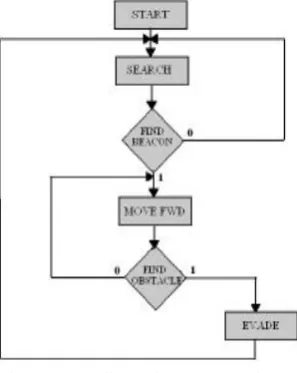
[image:2.595.343.515.180.247.2]Now days, control system design and analysis technologies are widely used in real-time development. Some problems in control system [2] are solved by hardware technology and some by the advance used of software tools saving the overhead of hardware and making it easier to carry out as many trials and research as possible in short period of time. Control systems can be analyzed easily and in depth with software tools such as Matlab [4]. A DC motor is an electric motor that runs on direct current (DC) electricity. The DC machine is considered to be basic electric machines. DC Motors can be used in various applications. Depending on its application it can have various sizes and rates. DC motor modeling, can be analyzed with control techniques of step response, impulse response and bode plot by using Matlab Simulink [3, 5]. By the help of this dc motor matlab modeling, results can be incorporated to many others types of motors with their desired applications. Here is the basic algorithm on which the tank model works.
Figure 3, Flow Chart of the tank algorithm
II. MODELLING OF ADCMOTOR
DC motors are widely used in robotics; their small size and high energy output make them excellent for powering the drive wheels of a mobile robots as well as powering other mechanical assemblies. The performance of the DC motor is characterized by its operating current and voltage, speed, torque, and the power. The need of creating a compromise of these characteristics is highly in demand, and triggers different modeling‟s exploiting several applications. To model and simulate DC motor following steps by step procedure is followed.
A. DC motor circuit diagram
To perform the simulation of the system, an appropriate model needs to be established.
Therefore, a model based on the motor specifications needs to be obtained. Fig. 4 shows the basic DC motor circuit with Torque and Rotor Angle consideration [6].
Figure 4, Schematic Diagram of a DC Motor
Where the following physical parameters and there abbreviations are used: Moment of inertia of the rotor = (J), Damping ratio of the mechanical system = (b), Electromotive force constant = (K), Electric resistance = (R), Electric inductance = (L), Motor torque = (T), Armature current = (I), Input or Source Voltage = (V), Output or position of shaft = (θ), Angular velocity = (ω).
B. System Equations
The motor torque T is related to the armature current i, by a torque constant K;
T = Ki (1) The electromotive force (emf) “e” is relative to angular velocity by;
e=Kdθ/dt (2) From Figure 1, we can write the following equations based on the Newton‟s law combined with the Kirchhoff's law:
J(d^2 θ)/(dt^2 )+bdθ/dt=Ki (3) Ldi/dt+Ri=V-Kdθ/dt (4)
C. Transfer Function
Figure 5, Schematic Diagram of a DC Motor
Using the Laplace transform, equations (3) and (4) can be written as:
Js^2 θ(s)+bsθ(s)=KI(s) (5)
LsI(s) +RI(s) =V(s)-Ks (s) (6) Where, “s” denotes the Laplace operator. From (6) we can express I(s) as:
I(s)=[V(s)-Ksθ(s) ]/(Ls+R) (7) By substituting it in (5) to obtain:
[image:2.595.92.241.370.557.2]Website: www.ijetae.com (ISSN 2250-2459, Volume 2, Issue 11, November 2012)
The above equation for the DC motor is shown in the block diagram in Fig. 5 below. From equation (8), the transfer function from the input voltage, V (s), to the output angle, θ, directly follows:
Ga(s) = θ(s)/(V(s))=K/({s[(R+Ls)(Js+b)+K^2 ]}) (9)
From the block diagram in Fig. 5, it is easy to see that the transfer function from the input voltage, V (s), to the angular velocity, ω, is:
Gv(s) = (ω(s))/(V(s))=K/({[(R+Ls)(Js+b)+K^2 ]}) (10)
D. Convertion to State Space Model
In the state-space form, the equations above can be expressed by choosing the rotational speed and electric current as the state variables and the voltage as an input. The output is chosen to be the rotational speed.
i ** 1 0.
E. Open Loop Response of the System
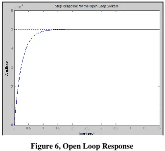
To see the open-loop response of the system, we have made a simple function named "dc_openloop" whose matlab [7] code is shown below. It takes the parameter values from user and plot open loop response of the system. It is extracted from transfer function obtained above for dc motor.
For: L=0.7, R=100, J=0.05, K=0.01, b=0.2 num=K;
den=[(J*L) ((J*R)+(L*b)) ((b*R)+K^2)]; step(num,den,0:0.1:5)
title('Step Response for the Open Loop System')
[image:3.595.67.260.342.402.2]The sample output of this open loop function is given below:
Figure 6, Open Loop Response
Another function named "dc_statespace" is created to see the open loop response of the dc motor system using state space method.
It again takes the input from user about the parameter values. The Matlab [8] code of this function is given below.
For: L=0.5, R=1, J=0.01, K=0.01, b=0.1
A= [-b/J K/J -K/L -R/L]; B=[0 1/L]; C=[1 0]; D=0;
step(A, B, C, D)
title('Step Response using state space')
The output of this function is:
Figure 7, Open Loop Response using State Space Method
F. Convert to Model Block and creating M-File
[image:3.595.333.530.500.575.2]We can use the transfer function obtained above to represent the block diagram for modeling dc motor in simulink environment.
Fig. 8 Closed-loop System Representing the DC motor
Before any consideration of the above equations, we must know the constant values of data, K, J, b, V, L and R. It depends on type of DC motor which is used in modeling. DC motor comes with specification sheet in which predefined values of constant are given. For our simulation purpose we can assume following values for constants.
Let us assume following values for the dc motor parameters.
V=10; J=0.01; b =0.00005; K =0.02; R =1; and L =0.7; Now, we can plot the step, impulse and frequency responses of the motor model:
V=10; J=0.01; b =0.00005; K =0.02; R =1; L =0.7; X = tf (1, [L R]);
current = feedback (X, K);
Y L i L R L K J K J b
i
/ 1 0 / / / /
[image:3.595.80.249.582.735.2]Website: www.ijetae.com (ISSN 2250-2459, Volume 2, Issue 11, November 2012)
[image:4.595.317.568.124.290.2]torque = current*K; speed=torque*tf(1,[J b]); angle=tf(1,[1 0])*speed; figure(9); step(out,0:0.5:10); figure(10); impulse(out,0:0.5:10); figure(11); bode(out,0:0.5:10);
Figure 9, Step Response
Figure 10, Impulse Response
Figure 11, Bode diagram
G. Simulink Model
The block diagram of Fig. 8 can be represented and created as a simulink model as shown in Fig. 12. The construction of this model is done using Simulink toolbox in Matlab.
Figure 12 .Simulink model of DC motor
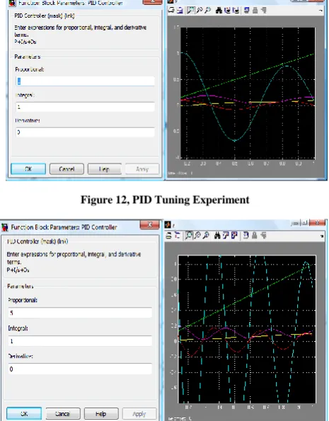
PID parameters are tuned by using Ziegler-Nichols tuning method (Marlin 2000) [12], this is the most widely used technique for tuning the control parameters for PID controller.
[image:4.595.64.265.191.679.2]In order to tune PID controller, first the Proportional gain must be set to minimum value and the other parameters (i.e. Integral and Derivative terms) should be set to give zero action. The Proportional gain should then be gradually increased until oscillations start to appear in the measured closed-loop system response. The gain should then be adjusted so that the oscillations are maintained with constant amplitude. The value of gain that is used to achieve this condition is termed the ultimate proportional gain (Gu) and the period (Pu) of the oscillation resulting from that gain must be measured. Based on these two values (i.e. Gu and Pu) and some standard formulae (Table 1), all of the controller parameters can be determined. In the Zeigler-Nichols formulae [12] for the closed loop tuning method, as summarized in the table below, the ultimate proportional gain is shown as Gu while Pu is the period of the closed loop system response using that particular ultimate proportional gain value.
Table 1, Ziegler Nichols formula for closed loop system
To simulate the dc motor model following parameters were used:
[image:4.595.342.522.584.647.2]Website: www.ijetae.com (ISSN 2250-2459, Volume 2, Issue 11, November 2012)
[image:5.595.318.560.121.285.2]We took different values for the constants to observe the behavior of system for different values of PID parameters.
[image:5.595.50.282.175.304.2]Figure 12, PID Tuning Experiment
Figure 13, PID Tuning Experiment
[image:5.595.47.280.179.477.2]Figure 14, PID Tuning Experiment
Figure 15, PID Tuning Experiment
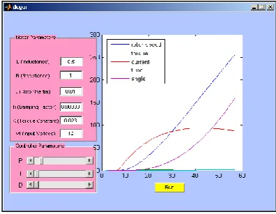
III. GRAPHIC USER INTERFACE (GUI)
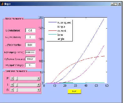
The graphic user interface (GUI) is created in matlab. It has two main panels which take input from the user. One panel is named "Motor Parameters" which takes inductance, resistance, rotor inertia, power, speed and motor voltage values from user. The second panel is named "PID Parameters" which takes value of proportional, integral and derivative values from user. Moreover GUI is facilitated by two buttons, one to start the simulation and the other to stop the simulation at any point. The figure below shows the building phase of GUI.
[image:5.595.39.283.397.660.2] [image:5.595.319.545.452.686.2]Website: www.ijetae.com (ISSN 2250-2459, Volume 2, Issue 11, November 2012)
IV. ARCHITECTURE DESIGN
[image:6.595.51.282.294.434.2]The architecture design is based on the (Time Triggered Protocol)TTP/C [9] communication protocol. TTP/C protocol allows fast communication between RenesasM16C62p microcontroller and memory. All previous perception decisions and current location information are stored in memory and this data is used on timely bases to identify the deadlock and also for adaptation. State of the art microcontroller from motor industry Renesas M16C62p [11] is used which includes a built-in I2C bus [10] for fast processing and dedicated pins for performing master/slave function considering multi processors platform communication.
Figure 17, Architecture Design.
[image:6.595.333.532.399.550.2]M16C62p also has built-in ADC and signal from ADC output port is fed to (Programmable Logic Counter) PLC which multiplies the signals frequency by constant factor. This signal is inserted to (Phase Lock Loop) PLL which locks the current frequency to the desired output frequency. Both signals: the output signal from RS232 and PLL are put in Stepper motor Driver. The implementation of the (Stepper Motor Driver) SMD is done in FPGA using VHDL. SMD configures the corresponding step according to the given degree of rotation, example if tank has to move 90 degrees towards right, then the output of the SMD will be 6 steps clockwise.
Figure 18, Algorithm for Speed control of intelligent tank
A software timer of 0.1ms is configured to read data from IR sensor and from LDR in Steps (1, 2) [11]. This information is used to process the current location and perception of the tank. Initially, previous perception is configured in the forward direction so as at the very beginning tank will move in the forward direction. This perception is stores in the memory using TTP/C [9] in Step-3. The previous perception and the current perception, calculated from the information received from the IR sensor and LDR data streams, are compared in Step-4. If there is any obstacle ahead then tank changes its direction and if there is any deadlock achieved then tank keeps on changing its direction to avoid deadlock steps (5 - 11). After configuring the right step and direction the SMD is accelerate to accelerate tank speed by activating the input signal of DC Motor Controller.
V. RESULTS
After developing the GUI, several simulation tests were carried out to see the response of the system. Here are some results for the speed controller simulations.
Figure19, When P:1 I:1 D:0 GUI Output for DC Motor
[image:6.595.332.530.573.726.2]Website: www.ijetae.com (ISSN 2250-2459, Volume 2, Issue 11, November 2012)
Figure 21, When P:10 I:10 D:10 GUI Output For DC Motor
VI. CONCLUSION
This paper develops the defining equations for a dc motor and along with performance testing of the model. It also illustrated the model-building capability of the Simulink toolbox and showed how to model and simulate a complete system of dc motor. This basic procedure can be expanded to build very complex simulation models of realistic engineering systems. This paper provides an example of model-building procedure and illustrates how new graphics-based software is making the analysis of real systems much more manageable. With tools like Matlab and Simulink, the engineer can concentrate on the design and performance of the system and not on the underlying numerical methods and coding needed to perform the actual computations. The proposed PID controller works fine to control the speed of the tank. A user friendly GUI, makes it lot simpler for the users to interact with the model.
VII. FURURE WORK
The DC motor control can be extended to the concept of Pulse width modulation (PWM). The need of power compensations in contemporary robot applications is a significant achievement for the survivability of the robot.
Instead of reducing the voltage operating the motor, the motor's power supply can be rapidly switched on and off. PMW is a technique in which a series of digital pulses is used to control an analog circuit. The length and frequency of these pulses determines the total power delivered to the circuit. The percentage of time that the power is on determines the percentage of full operating power that is accomplished. This type of motor speed control is easier to implement with digital circuitry and thus it might enhance the performance of the motor as well.
REFERENCES
[1 ] Adnan I. Elberjaoui Yakzan, Atif Ali Khan, Evor L. Hines, Daciana Iliescu, “Adaptive Control of an Intelligent Tank Using Fuzzy Logic”, UKSim 14th International Conference on Mathematical, Analytical Modeling and Computer Simulation, Mar 28- 30, 2012, Cambridge, UK.
[2 ] Norman S. NISE , Control Systems Engineering Fourth Edition, ISBN:978-0471-44577-7
[3 ] Steven T.Karris, „Introduction to Simulink with Engineering Applications‟, Orchard Publications, www.orchardpublications.com
[4 ] MathWorks, 2001, Introduction to MATLAB, the MathWorks, Inc.
[5 ] MathWorks, 2001, SIMULINK, the MathWorks, Inc.
[6 ] Benjamin C. Kuo , Automatic Control Systems, ISBN:975-8431-64-1
[7 ] Stephen J. Chapman (2004). MATLAB Programming for Engineers, Third Edition.
[8 ] MathWorks, 2001, Introduction to MATLAB, the MathWorks, Inc.
[9 ] H. Kopetz & G. GrÄunsteidl, TTP - A Protocol for Fault-Tolerant RealTime Systems, Journal of Computer, 27(1), pages 14{23, 1994.
[10 ] Renesas M16C, family for microcontrollers Platform: Http://www.renesas.com/media/products/.../m16c/M16C_Family_ Catalog.pdf.
[11 ]Software for I2c Renesas Microcontroller M16c62p full Specification:
Http://www.ecommerce.ismosys.com/ordering/docs/../I2C_full_s pec.pdf