University of Southern Queensland
Faculty of Health, Engineering and Sciences
Building Information Modelling:
An Explorative Study
A dissertation submitted by
Melanie Patterson
0019922397
In fulfilment of the requirements of
Bachelor of Construction Hons (Management)
ABSTRACT
This research was driven by a desire to understand the use of 4D and 5D Building Information Modelling (BIM) tools in medium scale Design and Build (D&B) organisations in Australia.
The utilisation of BIM tools in Australia is still in its infancy despite the reported advantages on the use of BIM methodologies for managing large scale projects. However, there is little information on the value of such methodologies for the management of D&B projects particularly with respect to medium scale construction companies. Furthermore, it was found that there lacked a consensus in the literature on the use of specific BIM tools, and which tools provided the most benefit to an organisation. Accordingly, the aim of this this research project is to examine the feasibility of utilising 4D and 5D BIM tools in managing and resolving key issues faced by medium scale D&B contractors.
In order to pursue the above aim, semi-structured interviews and a multiple case study approach was adopted. Semi-structured interviews were undertaken as a means to validate the findings from the literature review. Interviews undertaken with the Construction Manager, Project Manager and CAD Manager of a medium scale D&B organisation demonstrated that the D&B method of contracting improves both budget and timeframe performance on projects. The constructability of designs however, is integral to the level of success achieved.
The first case study for the project utilised a historical project in order to provide a first-hand understanding of the key issues and problems faced by medium scale D&B contractors. The results of the case study identified co-ordination between the design and construction teams are paramount to the D&B contractors’ performance. Revised designs on the project due to constructability concerns after the commencement of construction works was both costly and disruptive to the project. The ability to identify constructability concerns prior to commencing construction works ensures project success. Identifying the specific key concern on the project demonstrated the need for research into the use of 4D and 5D BIM for managing and resolving these issues.
The use of a second case study enabled 4D and 5D BIM tools to be retrospectively implemented on the same historical project, enabling a comparative analysis of the performance of the project to be undertaken. The results of the case study demonstrated that the use of 4D BIM tools enables the identification of constructability concerns prior to the commencement of construction works onsite. Identifying these concerns improved the project schedules predicted performance with the use of 4D BIM tools by one week and one day. 5D BIM tools utilised the 3D BIM model to price the alternative designs on the project. Whilst the use of 5D BIM proved advantageous in pricing the design change in a reduced timeframe, the outcome of the case study indicated that the use of 5D BIM in managing and resolving key issues is feasible, when used in collaboration with a 4D BIM tool.
Recommendations are provided to undertake further research on the use of 4D and 5D BIM tools on multiple medium sized D&B projects. The use of multiple projects would be used as a means to provide a consensus in the results, prior to recommending the implementation of 4D and 5D BIM tools in medium scale D&B organisations.
DISCLAIMER PAGE
LIMITATIONS OF USE
The Council of the University of Southern Queensland, its Faculty of Health, Engineering & Sciences, and the staff of the University of Southern Queensland, do not accept any responsibility for the truth, accuracy or completeness of material contained within or associated with this dissertation.
Persons using all or any part of this material do so at their own risk, and not at the risk of the Council of the University of Southern Queensland, its Faculty of Health, Engineering & Sciences or the staff of the University of Southern Queensland.
This dissertation reports an educational exercise and has no purpose or validity beyond this exercise. The sole purpose of the course pair entitled “Research Project” is to contribute to the overall education within the student’s chosen degree program. This document, the associated hardware, software, drawings, and other material set out in the associated appendices should not be used for any other purpose: if they are so used, it is entirely at the risk of the user.
CANDIDATES CERTIFICATION
I certify that the ideas, designs and experimentation work, results, analysis and conclusions set out in this dissertation are entirely my own efforts, except where otherwise indicated and acknowledge.
I further certify that the work is original and has not been previously submitted for assessment in any other course or institution, except where specifically stated.
Melanie Skene Patterson Student Number 0019922397
Date 29th October 2015
ACKNOWLEDGEMENTS
This research project is being carried out under the principal supervision of Dr Vasantha Abeysekera. I would like to thank Dr Abeysekera for providing me with much guidance and allowing me to communicate my ideas to him on this research topic. The time spent has enabled me to reach clarity on my objectives and provide focus to my research.
Contents
ABSTRACT ... iii
DISCLAIMER PAGE ... iv
CANDIDATES CERTIFICATION ... v
ACKNOWLEDGEMENTS ... vi
LIST OF FIGURES ... xi
LIST OF TABLES ... xiii
CHAPTER 1 – INTRODUCTION ... 1
1.1 Outline of the study ... 1
1.2 Introduction ... 1
1.3 The Problem ... 2
1.4 Research Objectives ... 3
1.5 Conclusions ... 3
CHAPTER 2 – LITERATURE REVIEW ... 5
2.1 Introduction ... 5
2.2 Design & Build Construction ... 6
2.2.1 Background ... 6
2.2.2 Advantages to the Design and Build method ... 6
2.2.3 Problems with the use of Design and Build procurement ... 8
2.2.4 Constructability of Designs ... 10
2.2.5 Summary of Design and Build projects ... 11
2.3 Building Information Modelling in the Construction Industry ... 12
2.3.1 Background ... 12
2.3.2 BIM Tools and Workflows Overview ... 15
2.3.3 BIM Global Adoption Strategies ... 18
2.3.4 BIM Contractual Challenges ... 22
2.4 Building Information Modelling (4D – Time) ... 23
2.4.1 4D BIM Overview ... 23
2.4.2 4D BIM Advantages ... 23
2.4.3 Overview of available 4D BIM Software... 25
2.4.4 Summary of 4D BIM ... 27
2.5 Building Information Modelling (5D – Cost) ... 28
2.5.1 5D BIM overview ... 28
2.5.2 5D BIM Advantages ... 28
2.5.3 Available Software Packages ... 29
2.5.4 Summary of 5D BIM ... 31
2.6.1 Implementation of BIM in an Organisation ... 31
2.7 Literature Review Summary ... 32
CHAPTER 3 – METHODOLOGY ... 35
3.1 Objectives Overview ... 35
3.2 Organisation Overview ... 37
3.3 Selection of BIM Tools ... 37
3.4 Interviews ... 37
3.4.1 Purpose ... 37
3.4.2 Interviewee Selection ... 38
3.4.3 Interview Process ... 38
3.4.4 Data Analysis ... 40
3.5 Case Study Research ... 40
3.5.1 Multiple-Case Design Case Study ... 40
3.5.2 Case Study Protocol ... 40
3.6 Pilot Case Study ... 43
3.6.1 Pilot Enquiry ... 43
3.6.2 Small Scale Test Project ... 43
3.6.3 Method ... 44
3.7 Historical Project Case Study 1 – No BIM Tools ... 45
3.7.1 Objective ... 45
3.7.2 Selection of Project ... 45
3.7.3 Data Collection ... 46
3.7.4 Data Analysis ... 46
3.8 Historical Project Case Study 2 – BIM Tools Implemented ... 46
3.8.1 Objective ... 46
3.8.2 Selection of Project ... 47
3.8.3 Data Collection ... 47
3.8.4 Data Analysis ... 48
3.9 Resource Requirements ... 48
3.10 Risk Analysis ... 49
3.11 Project Timeline ... 49
CHAPTER 4 – BIM SOFTWARE USER GUIDE ... 50
4.1 Introduction ... 50
4.2 Autodesk Navisworks Manage 2016 ... 50
4.2.1 Opening Navisworks Manage software ... 50
4.2.2 Import Project 3D BIM Model ... 51
4.2.4 Assigning Task Types ... 53
4.2.5 Selection Sets ... 54
4.2.6 Project Schedule Simulation ... 58
4.3 Exactal CostX 2016 ... 61
4.3.1 Import Project 3D BIM Model ... 61
4.3.2 Dimensions from 3D BIM Model ... 63
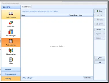
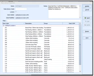
4.3.3 Importing Rate Libraries into CostX ... 65
4.3.4 Workbooks ... 67
4.4 Summary ... 70
CHAPTER 5 – RESULTS & ANALYSIS ... 71
5.1 Introduction ... 71
5.2 Interviews ... 71
5.2.1 Introduction ... 71
5.2.2 Response from Interviewees ... 72
5.2.3 Summary - Interviews ... 78
5.3 Historical Project Case Study 1 – Commercial Development ... 79
5.3.1 Introduction ... 79
5.3.2 Overview ... 79
5.3.3 Contract ... 80
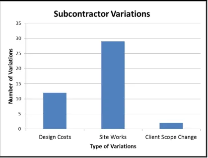
5.3.4 Subcontractor Variations ... 81
5.3.5 Request for Information ... 86
5.3.6 Project Schedule Performance ... 87
5.3.7 Summary of Results – Historical Project Case Study 1 ... 89
5.4 Pilot Case Study ... 90
5.4.1 Introduction ... 90
5.4.2 Design ... 90
5.4.3 Data Collection ... 90
5.4.4 Summary of Results – Pilot Case Study ... 94
5.5 Historical Project Case Study 2 – Commercial Development: BIM Tools Implemented ... 95
5.5.1 Introduction ... 95
5.5.2 Design ... 95
5.5.3 Project Schedule ... 96
5.5.4 Data Collection – 4D BIM – Building Approval Design Model ... 96
5.5.5 Data Collection – 4D BIM – Final 3D BIM Design Model ... 105
5.5.6 Data Collection – 5D BIM – Comparison of Design Models ... 111
5.6 Results and Analysis Summary ... 118
CHAPTER 6 - CONCLUSIONS ... 120
6.1 Introduction ... 120
6.2 Conclusions ... 120
6.3 Further Research and Recommendations ... 121
6.4 Limitations ... 122
APPENDICES ... 123
APPENDIX A – Project Specification ... 123
APPENDIX B – Project Timeline ... 124
APPENDIX C – Historical Project Case Study 1 - Subcontractor Variations ... 125
APPENDIX D – Historical Project Case Study 2 - Predicted Project Schedule ... 126
APPENDIX E – Historical Project Case Study 2 – Exactal CostX Elemental Report . 128 APPENDIX F – Historical Project Case Study 2 – Design Change BOQ’s ... 130
REFERENCES ... 132
LIST OF FIGURES
Figure 2.1 - Properties of a building element in Autodesk REVIT (Source - Author) ... 14
Figure 2.2 - BIM Workflow (Weatherford 2014) ... 15
Figure 2.3 - – Summary of functions of nD BIM (Mubarak 2015)... 17
Figure 2.4 - Enabling applications extract data from design models and provide valuable analysis and simulation (BIM Building Information Modeling A Supplement to New York Construction) ... 18
Figure 2.5 - BIM Maturity Model (A Report for the Government Construction Client Group: Building Information Modelling (BIM) Working Party Strategy Paper 2011) ... 20
Figure 2.6 – How Collaboration delivered on a Huge Hospital Project (2013) ... 30
Figure 3.1 - Research Methodology Map... 36
Figure 4.1 - Navisworks Manage default opening screen ... 50
Figure 4.2 - 3D BIM model imported into Navisworks Manage ... 51
Figure 4.3 - Navisworks Manage Timeliner Tab ... 51
Figure 4.4 - Navisworks Manage Data Sources Tab ... 52
Figure 4.5 - Navisworks Manage Field Selector ... 52
Figure 4.6 - Navisworks Manage Timeliner project schedule ... 53
Figure 4.7 - Navisworks Manage Selection Tree ... 54
Figure 4.8 - Navisworks Manage assigning tasks in the Selection Set ... 55
Figure 4.9 - Navisworks Manage Selection Tree search ... 55
Figure 4.10 - Navisworks Manage Selection Tree model search ... 56
Figure 4.11 - Navisworks Manage Selection Tree task assignment ... 56
Figure 4.12 - Navisworks Manage Timeliner Selection Set link ... 57
Figure 4.13 - Navisworks Manage Timeliner – Attaching model elements to the project schedule ... 57
Figure 4.14 - Navisworks Manage project schedule simulation settings ... 58
Figure 4.15 - Navisworks Manage Simulation – “roof under construction” ... 59
Figure 4.16 - Navisworks Manage Simulation – “roof complete” ... 59
Figure 4.17 - Navisworks Manage Simulation – “wall under construction” ... 60
Figure 4.18 - Navisworks Manage Simulation – “wall complete and cladding under construction ... 60
Figure 4.19 - CostX default screen ... 61
Figure 4.20 -CostX Drawing Ribbon ... 61
Figure 4.21 - 3D BIM model imported into CostX ... 62
Figure 4.22 -CostX Object Properties ... 63
Figure 4.23 - CostX Dimensions Ribbon ... 63
Figure 4.24 - CostX Dimension Groups ... 64
Figure 4.25 - CostX Transparent Display selections ... 64
Figure 4.26 - CostX BIM model Dimension Group selections ... 65
Figure 4.27 - CostX Import Rate Library selections ... 66
Figure 4.28 - CostX Rate Library Properties ... 66
Figure 4.29 - CostX Rate Library import ... 67
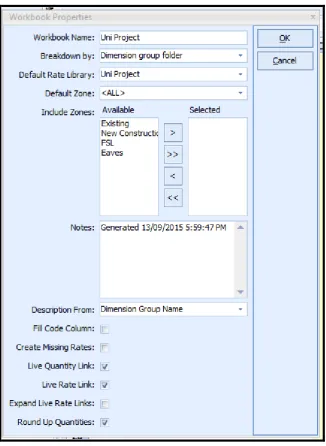
Figure 4.30 - CostX Workbook Properties... 68
Figure 4.31 - Dimension group import to workbooks ... 68
Figure 4.32 - CostX Workbook Level 2 ... 69
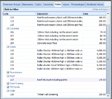
Figure 4.33 - CostX Rates Tab ... 69
Figure 4.34 - CostX Workbook with rates inclusion ... 70
Figure 5.1 - Subcontractor Variation Summary ... 83
Figure 5.2 - Project RFI Summary ... 86
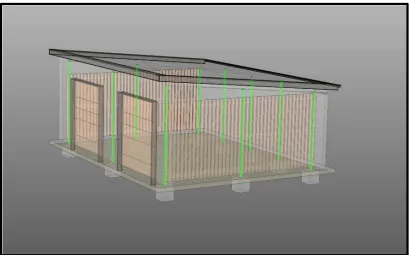
Figure 5.3 - Test Project Design ... 90
Figure 5.4 - Budget Cost Estimate ... 91
Figure 5.5 - Modified Test Project Design ... 91
Figure 5.6 - CostX Comparison Model ... 92
Figure 5.7 - Test Project Schedule Modifications ... 92
Figure 5.8 - Test Project Modified Schedule Simulation ... 93
Figure 5.9 - Test Project Selected Schedule Date ... 93
Figure 5.10 - Test Project Cost Loaded Schedule ... 94
Figure 5.11 - 3D BIM Model (Building Approval Stage) ... 97
Figure 5.12 - Project Schedule (Building Approval Stage) ... 97
Figure 5.13 - Autodesk Navisworks Selection Sets ... 98
Figure 5.14 - Level 2 Office Layout using Autdesk Navisworks Hide Element ... 99
Figure 5.15 - Building Approval Stage (Viewpoint 1) - Works Complete Week 9 ... 99
Figure 5.16- Building Approval Stage (Viewpoint 1) - Works Complete Week 11 ... 100
Figure 5.17- Building Approval Stage (Viewpoint 1) - Works Complete Week 13 ... 101
Figure 5.18- Building Approval Stage (Viewpoint 1) - Works Complete Week 15 ... 101
Figure 5.19- Building Approval Stage (Viewpoint 1) - Works Complete Week 19 ... 102
Figure 5.20 - Building Approval Stage (Viewpoint 2) - Works Complete Week 9 ... 102
Figure 5.21- Building Approval Stage (Viewpoint 2) - Works Complete Week 11 ... 103
Figure 5.22- Building Approval Stage (Viewpoint 2) - Works Complete Week 13 ... 104
Figure 5.23- Building Approval Stage (Viewpoint 2) - Works Complete Week 15 ... 104
Figure 5.24- Building Approval Stage (Viewpoint 2) - Works Complete Week 17 ... 105
Figure 5.25 - Final BIM Model - Works Complete Week 5 ... 106
Figure 5.26 - Final BIM Model - Works Complete Week 9 ... 107
Figure 5.27 - Final BIM Model - Works Complete Week 11 ... 107
Figure 5.28 - Final BIM Model - Works Complete Week 13 ... 108
Figure 5.29 - Final BIM Model - Works Complete Week 15 ... 108
Figure 5.30 - Final BIM Model - Works Complete Week 19 ... 109
Figure 5.31 - Final BIM Model - Works Complete Week 26 ... 109
Figure 5.32 - 3D BIM Model (Building Approval Stage) - Uploaded to Exactal CostX .. 112
Figure 5.33 - Final 3D BIM Model - Uploaded to Exactal CostX ... 112
Figure 5.34 - Exactal CostX Layers Function ... 113
Figure 5.35 - 3D BIM Model Revision Comparison ... 113
Figure 5.36 - 3D BIM Model Revision Comparison (Revisions, Additions and Deletions Only) ... 114
Figure 5.37 - Drawing Revision Log Extract ... 114
Figure 5.38 - BOQ Building Approval BIM Model ... 115
Figure 5.39 - BOQ Final Design BIM Model ... 115
Figure 5.40 - Subcontractor Costs Week 11 ... 116
LIST OF TABLES
Table 2.1 – Key Findings of D&B Literature Review ... 33
Table 3.1 – Interviewee Selection ... 38
Table 3.2 – Key Findings from D&B Literature Review ... 38
Table 3.3 – Interview Questions ... 39
Table 3.4 – Small Scale Test Project data collection questions ... 44
Table 3.5 – Case study selection criteria ... 45
Table 3.6 – Case study selection criteria ... 47
Table 3.7– Research project resource requirements ... 48
Table 3.8 – Risk Management chart for works undertaken preparing dissertation ... 49
Table 5.1 – Findings from D&B Literature Review ... 72
Table 5.2 - Design Cost Subcontract Variations ... 83
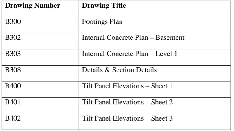
Table 5.3- Drawings used in Design Cost analysis ... 84
Table 5.4 - Project RFI’s ... 86
Table 5.5 - Project Extension of Time Claims ... 87
Table 5.6 - Construction Programme Analysis ... 88
Table 5.7 - Construction Programme Analysis ... 88
Table 8 - Project Schedule Performance - 4D BIM Tools ... 110
Table 9 - Extension of Time Claim Register: Building B Delays ... 110
Table 10 - Project Schedule Performance - 4D BIM Tools: EOT Delays Included ... 111
CHAPTER 1
– INTRODUCTION
1.1
Outline of the study
The use of the Design and Build (D&B) method on construction projects provides a significant advantage to both clients and contractors. Control of the design affords the contractor with the ability to regulate the projects budget and also construction timeframes, improving the overall success of a project.
My current employment is with a successful medium scale Design and Build Organisation. Through the use of the D&B method, the organisation is able to reduce project timeframes, as well as improve budget performance for the client. Issues arise on occasions however; therefore there is an opportunity for continuous improvement. The need for the project was identified from this desire for improvement. For the purposes of this report, the company will be referred to as “The Organisation”.
New and emerging Building Information Modelling (BIM) tools are being introduced into the market that are used for the overall management of the project throughout its entire lifecycle. The research was driven by the desire to understand the use of 4D and 5D BIM tools in medium scale Design and Build organisations in Australia, and the feasibility of utilising these BIM tools in managing and resolving key issues.
1.2
Introduction
BIM is a design tool that has been in use in the architectural, engineering and construction industry for some time. The use of the BIM model in the design of a project enables the project team, to utilise the 3D design model as an object database, containing specific information relating to each of the building elements (buildingSMART-Australasia 2012). This information contained within the BIM model, is the key aspect that differentiates the BIM model from other 3D modelling tools.
Autodesk Revit, BIM software has been the principal design software used by the design office in the organisation for approximately ten years for building modelling and design. More recently TEKLA, also BIM software has been in use for approximately two years for structural steel detailing. The current use of both software’s in The Organisation are however limited to 3D BIM.
Emerging BIM tools are available for the use by all project stakeholders that aid in the management of construction projects. 4D BIM tools are available according to Mukherjee and Clarke (2012) that aid in construction planning, and also the ability to visualise the construction sequence prior to commencing construction of the project. Through the integration of the 3D BIM model and the projects schedule, 4D BIM tools can then be used to simulate the construction schedule, enabling the construction of the project to be reviewed prior to commencing works onsite (Hardin & McCool 2015).
Furthermore, 4D BIM tools can be used for constructability review processes on project, whereby both site constraints and challenges are able to be identified and resolved prior to commencing works onsite (Hartmann & Fischer 2007). The benefit of implementing 4D BIM tools therefore, is improving both the communication and coordination between the project team, from the commencement of the project in the design phase.
5D BIM tools facilitate the integration of the 3D BIM model and the projects rate schedules. By utilising the information in the 3D BIM model such as material specifications and quantities, the 5D BIM tools are able to combine this information with the rate schedules to produce project estimates (Mubarak 2015). A significant advantage of the adoption of 5D BIM tools, according to Forgues et al. (2012) is the project team is able to undertake estimate comparisons throughout the lifecycle of the project, rather than when the projects designs reach a specific stage.
The use of 5D BIM on projects also enables project team members to price both variations and scope changes, in a shortened period of time. A benefit to utilising 5D BIM therefore is that variations and scope changes can occur when time is of the essence in the project and therefore the estimate updates can be produced almost instantaneously (Reaching Target Project Costs with 5D BIM Estimating 2015).
Previous research on the use of 4D and 5D BIM tools has identified significant advantages, improving construction sequencing and project estimate comparisons. This research however, has been limited to use on large scale projects and not specifically used by Design and Build contractors. This research project will therefore investigate the feasibility of utilising these BIM tools to manage and resolve key issues faced by medium scale D&B contractors.
1.3
The Problem
The D&B method of contracting relies upon the accuracy of the constructability of designs. Co-ordination between the design and construction teams is paramount to improving the constructability and also the success of the D&B project (Greenhalgh & Squires 2011). Improved coordination also enables the construction team to increase the construction team members input in the design phase of the project.
As a means to improve areas of the design that prove difficult to construct, constructability reviews should be undertaken. In order to improve the process and also gain valuable construction insight, the construction team must be involved in the process. The constructability review process is an aspect of the D&B method that highlights the significance of the collaboration between the design and construction teams (Cushman & Loulakis 2001).
While the D&B method improves the constructability review process, there are still occurrences on projects where designs are complete, and the review has not identified any areas of concern, problems are therefore only uncovered once construction works have commenced onsite. Changes made to designs after construction works have commenced are therefore both costly and time consuming to resolve. In order to resolve these design changes, the projects overall success can be affected.
Despite the consensus in the research of the benefits in the adoption of BIM tools on projects, research has not previously identified the benefit of using 4D and 5D BIM tools in medium scale D&B organisations. This dissertation therefore focusses on the value that the implementation of BIM tools will provide to medium scale D&B organisations, to aid in the constructability review processes and therefore alleviating the problems that are encountered from time to time.
1.4
Research Objectives
The aim of this research was to examine the feasibility of utilising 4D and 5D BIM tools for managing and resolving key issues faced by contemporary medium-scale Design and Build contractors.
In order to achieve this objective the following sub-objectives have been formulated: 1. Establish risks faced by design and build contractors through an extensive
literature review.
2. Undertake extensive literature review to research and evaluate currently available Building Information Modelling software and the developments in the software since its inception, focussing on the integration between 3D and the elements of 4D (Time) & 5D (Cost).
3. Undertake interview with key organisation members in order to validate the findings from the literature review.
4. Undertake a historical case study on one of our Organisations completed projects in order augment these concerns (Historical Case Study 1).
5. Undertake Pilot Case Study using a small scale test project created in Autodesk REVIT and selected 4D and 5D BIM tools, as a means to provide an understanding of the tools and resolve the usage of the tools for the remainder of the research project.
6. Apply selected BIM 4D and 5D BIM tools to the historical project and then undertake a case study (Historical Case Study 2) to resolve the value of using these tools in managing and resolving the issues that are encountered.
1.5
Conclusions
This dissertation aims to determine the feasibility of utilising 4D and 5D BIM tools in managing and resolving key issues faced by medium-scale D&B contractors.
The results of the research are expected to identify that there is an advantage in the adoption of BIM tools in medium scale design and build organisations, for use on projects. 4D BIM tools are expected to improve the constructability design review process, which will result in improved project schedule performance and a reduction in costly design changes. The results of the utilisation of 5D BIM tools is expected to aid in improving the pricing of design changes and cost management on projects. The use of 4D and 5D BIM tools are expected to be a feasible method of managing and resolving key issues faced by medium-scale D&B contractors.
A review of the literature for this research is included in Chapter two. The literature review has been undertaken to establish both the risks faced by D&B Contractors, and also the advantages to the use of 4D and 5D BIM tools. Chapter two will aim to achieve sub-objectives 1 and 2 that have been established for the research project.
Chapter three of the dissertation includes the research methodology that has been implemented to carry out the research project works. The chapter includes both the case study protocol and interview guide that has been used to complete the research for the project.
Chapter four has been included in the dissertation as a software user guide. As the software adopted for use in the project is new, the guide has been included as a means to provide reliability to the research as all processes that were undertaken are included.
Chapter five includes the results and analysis section of the dissertation. The results included in Chapter five are the results from the interviews with key organisation members, the historical case study, small scale test project and the second historical case study with BIM tools implemented. The contents of this chapter will achieve sub-objectives 3, 4, 5 and 6.
Chapter six of the dissertation includes the conclusions and recommendations for the project. The objective of the research is to examine the feasibility of using 4D and 5D BIM technologies for managing and resolving key issues faced by contemporary medium-scale Design and Build contractors. The recommendations will therefore include a determination on the value of the BIM tools, and the benefit of adopting them in the organisation.
The outcomes of this study will be used as a means determine the recommendation to The Organisation, for the adoption of 4D and 5D BIM tools for use on future D&B projects.
CHAPTER 2
– LITERATURE REVIEW
2.1
Introduction
The aim of this literature review is to examine key issues that are faced by medium-scale Design and Build (D&B) contractors. In addition to this, the literature review seeks to investigate currently available Building Information Modelling (BIM software), and the developments of BIM. An evaluation of the integration of the 3D BIM model and the 4D and 5D BIM tools will also be undertaken.
Construction projects are becoming increasingly more complex, with shorter timeframes and reduced budgets. In order to ensure projects success, adequate planning therefore must be undertaken. When appropriate planning isn’t undertaken however considerable cost and time overruns can be experienced. A study by Zuppa, Issa and Suermann (2009) highlighted that in the United States in 2008 there was approximately $600 Billion dollars’ worth of spending that was considered waste, and could be attributed to poor planning through inefficient communication between relevant parties on the project, poor design, or poor productivity on the project.
BIM is a 3D modelling concept that has been introduced to the Architectural, Engineering and Construction Industry. The concept has enabled the design of a project to be undertaken through the use of a collaborative and digital model, which has provided much benefit to organisations to establish co-ordination in designs between different building aspects (Azhar 2011).
Planning and Scheduling in the traditional method on a project consists of a Project Manager utilising 2D plans to visualise the project to identify and schedule tasks and timeframes in planning methods such as the Critical Path Method or the Line of Balance (Jongeling & Olofsson 2007). While these methods are beneficial on projects and have been successful, they are however subject to differing interpretations based on how the drawings are read. BIM software allows the user to be able to simulate the construction sequence of the project, and then in turn identify any potential clashes on the project ensuring the project schedule produced is accurate and clear to all stakeholders in the project.
Traditional estimating methods utilise 2D drawings to undertake measurements of the project to produce quantity take-offs (Monteiro & Poças Martins 2013). The quantity take offs are then used in conjunction with rates and Bill of Quantities that have been established within the organisation for the various work packages. An issue that estimators face on projects however is the time constraints to undertake quantity take-offs multiple times. The use of 5D BIM tools enables the estimator to utilise the BIM model to undertake numerous estimates as required throughout the design phase of the project (Mitchell 2012).
2.2
Design & Build Construction
2.2.1 Background
The Design and Build (D&B) procurement method in construction projects, enables the client to engage a single firm for the delivery of both the design and construction of the project, reducing the contractual responsibility to one firm (Konchar & Sanvido 1998).
An alternate version of the D&B arrangement is available to clients that reduce the involvement of the D&B contractors in the design phase of the project; however the level of design responsibility remains the same. Novated D&B can be used by clients to engage consultants to complete the design prior to submitting request for tenders. Once a contractor is engaged, the responsibility for the design is then transferred from the client to the contractor (Murdoch & Hughes 2000).
Tenders submitted by contractors on a project using the D&B contract type includes a proposal to be submitted based on the request for proposal procurement method used by the client. The proposal submitted by the contractor can contain preliminary proposal drawings, project specifications or outlines and the tendered price for the project (Ndekugri & Turner 1994).
A key component to the success of a D&B project is the initial clarity of scope by the client. The scope provided by the client includes the established performance criteria which outlines the requirements that are expected to be achieved by the contractor (Cushman & Loulakis 2001). In order for the contractor to successfully interpret the client’s requirements for the project however, the performance criteria must be comprehensive and clearly defined.
The basis of the performance specification utilised by the client in the D&B contract determines the overall result that is required from the project, however the specification does not dictate specific materials or methods that must be incorporated into the project which are prescriptive or design specifications. Limiting the specification to performance only, the overall outcome of the project can be improved through innovative ideas and improved efficiencies in the design and construction (Molenaar, Songer & Barash 1999).
The use of the D&B contract type enables the contracted party to undertake the works based on a set of defined deliverables and performance criteria that have been established by the client. The works are undertaken for a set price and a set completion timeframe. The level of detail in the design required by the contractor therefore is required to fit within the contractors proposed budget and the contract completion schedule only to achieve the clients performance criteria (Gransberg & Molenaar 2004).
2.2.2 Advantages to the Design and Build method
As reported by Konchar and Sanvido (1998) in a comparative case study on the performance of D&B projects versus other procurement methods, the D&B project had a construction speed at least 12% faster and 6.1% less costly than that of the Design-bid-Build procurement method which is a considerable advantage in the utilisation as a procurement method.
Results of a historical case study undertaken on 104 completed public sector projects in the United States found that 55% of projects undertaken using the D&B procurement method were completed within 2% of the project budget, a further 8% of projects were under the project budget by 3% or more. Approximately 28% of the projects were within 3 to 5% of the project budget and the remaining 9% of the projects were over budget by 5% or more. The case study further compared three D&B methods based on the status of design completion at the time of the Request for Proposal. The three methods were more than 50% of design completed, less than 35% of design completed and qualifications based with less than 10% of the design completed. The study found that the best performing D&B projects were those that had less than 35% of the design completed at the time of the Request for Proposal. The least performing projects were qualifications based projects which were attributed to lack of competition during the proposal stage of the projects (Molenaar, Songer & Barash 1999).
Results of the same case study also identified that 77% of the projects were also completed within 2% or better of the project schedule, 10% of the projects were under the project schedule by 3% or more, and approximately 10% of the projects were completed within 3 to 5% over the anticipated project schedule. The remaining projects were completed at least 6% over the projects schedule. The study found that the best performing projects in terms of the project schedule were also those had less than 35% of the design completed at the time of the Request for Proposal with the least performing projects being qualifications based projects (Molenaar, Songer & Barash 1999).
A key criterion for the selection of the D&B method is the ability to shorten the timeframe of a project from the commencement of design to completion. This shortened timeframe can happen due to the ability of the design process and construction activities being undertaken concurrently. This enables the contractor to be undertaking works onsite prior to the final design being completed (Ling & Leong 2012).
The D&B method enables the project team to improve coordination on the project. The improved coordination enables the construction team to increase the construction team members input in the design phase of the project. The improved coordination is also a contributing factor to the reduction of project timeframes if the D&B method is utilised (Greenhalgh & Squires 2011).
The potential for claims raised by the contractor can be reduced when utilising the D&B method. Examples of such claims are, extension of time claims that can be raised for the delay in the client providing required information or responses for the project. Due to the contractor assuming all responsibility for completing the project within the specified project schedule as well as the responsibility for the design, the potential for these claims are therefore reduced (Davis, Love & Baccarini 2008). Construct only projects can be subjected to delays which can include claims by the contractor to the client for delays in providing design documentation; these claims however are not experienced on D&B projects.
2.2.3 Problems with the use of Design and Build procurement a. Increased Financial Risks
D&B projects are tendered by contractors with an amount of uncertainty due to the lack of design information available at the time of pricing the project. As discussed in Section 2.2.2, the best performing D&B projects were those with less than 35% of the design completed at the Request for Proposal stage. Contractors can therefore be expected to provide a fixed price for the project, even with a considerable amount of information lacking. In order for the contractor to price the project to remove potential financial risks associated with the project unknowns must be allowed for (Lam, Chan & Chan 2003).
In order for contractors to allow for unknowns, contingencies can be added to the estimate. A contingency or allowance is utilised to provide an accurate estimate for a project where it is known that information is lacking during the tender stage of the project. Peurifoy and Oberlender (2002) highlight that the contingency amount should be determined in collaboration with the estimating team and the project management team to ensure that the correct allowance has been accounted for. Levy (2012) also highlight that the use of contingency within D&B contracts enables the contractor to reduce potential financial risks.
Murdoch and Hughes (2000) identify that a method utilised by clients to reduce the financial risk associated with the D&B method, is to use guaranteed maximum price (GMP). Utilising the GMP method, the price for the project is capped at a predetermined sum. In order to reduce the final cost of the project the client can include incentives that benefit the contractor should the project be completed under the GMP. The D&B method therefore reduces the financial risk for the client as all risk lies with the contractor to complete all design and construction works to achieve the clients’ requirements within the agreed contract sum.
b. Increased Design Responsibility
An inherent risk in a contractor undertaking a D&B project is that the contractor assumes all responsibility associated with the design of the project as well as the construction. The increased risk in design responsibility is a direct cause of utilising the D&B method as the design is undertaken by the contractor which includes the accuracy of the design (Kelleher 2005). The contractor is therefore liable for all costs and potential additional time associated with the rectification or modification of works due to errors within the design (Loots & Charrett 2009).
In comparison to the D&B method, Construct only contracts are contracts where the contractor is engaged to undertake only the construction works for the project. The client engages separate design consultants to complete all design works for the project. Therefore in this method, there is no design responsibility for the contractor. Construct only contracts allow for the contractor to claim additional costs for works that have resulted from errors within design (Loots & Charrett 2009).
D&B projects require the contractor to undertake the design of the project and therefore the responsibility of this design component remains with the contractor. The design responsibility also includes an obligation for the design to be fit for purpose. Fit for purpose extends beyond the design being completed without errors, it is an obligation that when the project is completed, it must meet all of the required and intended purposes (Loots & Charrett 2009).
Brierley, Corkum and Hatem (2010) also agree that in the D&B method, the owner is able to assign all risk associated with the design to a single contractor. However it is noted that for this to be an effective method of contracting, the contractor must be given control over decisions made regarding the design. The owner therefore must rely upon the scope provided to the contractor during the request for proposal stage of the project. As discussed in Section 2.2.1 previously, for project success, the clarity of the scope is critical.
A standard form contract used by clients and contractors engaging in D&B projects includes AS4902 from Standards-Australia (2000), which contains contractual clauses that specifically cover the design obligations of the contractor. Specifically Clause 2.2 of the contract includes details of the contractors warranty to carry out the works on the project so as to ensure that they will be fit for their purpose when completed.
A standard form contract AS4000 from Standards-Australia (1997) is used by clients and contractors engaging in Construct only projects where the contractor undertakes only the construction works for the project. This contract contains contractual clauses that specify the requirement for the contractor to complete the works that are agreed as the works under contract. The contract however does not include fit for purpose obligations for the contractor, only the completion of works for the project that are compliant with the design provided by the client.
c. Timing of Scope Changes
The advantage of the overlapping of design and construction in D&B projects, can also lead to potential problems when design changes are requested by the client (Lam, Chan & Chan 2003). If a change of design is directed, and the construction works have already commenced in this area the change will also incur rework costs to enable the change to be incorporated into the design. Pricing of variations of this nature can be difficult, due to the incompleteness of the designs, and the inability for the client to understand construction works are further advanced than the completion of the projects design.
Turner, Jung and Hwang (2012) also agree that there is an increase in costs associated with changes to the design requested by the client in the D&B method. The increase in costs can be attributed to the overlapping of the design and construction phases of the project and the addition costs associated with the modification of works already completed.
d. Overlapping of Project Phases
As reported by Chang, Shen and Ibbs (2010) in the case study on coordination in five ongoing D&B projects, issues arise in D&B projects when designs are not appropriately coordinated with the construction schedule for the project. Projects can experience delays in the earlier trades in the construction schedule, where construction works are completed onsite however further design documentation is required to be completed to allow the construction schedule to continue. Without the required design, construction works cannot proceed, therefore the project is delayed. Interviews with the contractors of the projects in the case study highlighted that concurrence or overlapping of the design and construction phases is difficult to schedule on the project, and also hard to control. These coordination issues result in delays onsite, and thereby reducing a key advantage of the D&B method.
Murdoch and Hughes (2000) identify that the fast-tracking in D&B projects by commencing construction works prior to the completion of the overall design for the project has advantages in reducing the construction timeframe, as discussed previously in Section 2.2.2. There is however disadvantages when changes are made to the design that affects the construction works already completed. In order to incorporate the design changes, the works already completed need to therefore be changed which increases both time and costs on a project.
Hashem (2005) also agrees that a problem in the D&B method is when the design and construction activities are overlapped so far that the construction works must halt to enable the design to catch up. The error in overlapping has occurred where the commencement of construction works have been scheduled too early in the design phase of the project, so that the design is unable to maintain the required schedule to meet the requirements of the construction team. The solution however is not to remove the overlapping of the D&B phases of the project, because the removal of this overlapping will also remove one of the key advantages of the D&B method.
2.2.4 Constructability of Designs
Constructability reviews should be undertaken in D&B projects as a means to identify areas of the designs that may prove difficult to construct. The input from the construction team in this process enables the design to be reviewed from a construction aspect. This is an area of the D&B method that highlights the significance of the collaboration between the design and construction teams (Cushman & Loulakis 2001).
In a study undertaken by Ndekugri and Turner (1994) it was reported that the utilisation of the D&B procurement method reduced ambiguity in the constructability of the designs. This reduction can be attributed to the increased involvement in the design process by the construction team. Including the construction team in the initial design of the project enables the design team and construction team to work collaboratively in order to achieve the best design for the project in terms of constructability.
Brierley, Corkum and Hatem (2010) also agree that a key advantage of the D&B process is the ability to undertake constructability reviews of the design. A key factor in completing this review is the early involvement of the construction team in the design review. Improving the constructability of designs also aids in a reduction of the construction timeframes. This identifies the importance of the collaboration between the design and construction teams, in ensuring the constructability of designs.
2.2.5 Summary of Design and Build projects
The use of the D&B method provides many advantages to both clients and construction firms. The D&B method enables the client to engage one firm to complete both the design and construction of the project, reducing the contractual responsibility to one firm. This also aids in the reduction of potential claims made by the contractor to the client.
Studies undertaken on the performance of the D&B method have established that projects are able to achieve shorter timeframes than other methods, which can be attributed to the ability for design and construction activities to be undertaken concurrently. In addition to this, studies have identified the improved performance of D&B projects achieving project completion within the specified budget.
While there are important advantages to adopting the D&B method on projects, the D&B method also raises a number of problems for contractors on projects. Contractors undertaking D&B projects can be required to submit a fixed price for the project, when the design has not been completed and therefore there are a number of unknowns. The financial risk then lies with the contractor to complete the project within the specified budget.
Undertaking the design for the project as well as construction requires the contractor to assume all responsibility associated with the correctness and suitability of the design. This differs from other methods, whereby in construct only projects the design liability remains with the client. This liability can have an effect on both the projects budget, and schedule should there be errors within the design that the contractor cannot claim for compensation from the client.
Scope changes can occur on projects that require variations to be priced. The timing of scope changes on D&B projects can affect the cost of these changes. While the design may still be underway, construction works can be commenced which can affect the overall cost of the change.
The overlapping of the design and construction phases of a project enables the project to be completed in a shorter timeframe than utilising other methods. If the overlapping of the phases is not sequenced correctly and the construction phase is commenced prior to the design being completed to a suitable stage, delays can be experienced onsite while the design is being completed. In addition to this, the cost of scope changes can increase due to the advancement of works onsite requiring rework.
Constructability of designs improves the project schedule performance. Construction team input in the design phase of a project provides insight into the construction scheduling of a proposed design. The use of the D&B method improves the constructability review process; however the collaboration between the design and construction teams of a project is paramount to improving the constructability of designs.
2.3
Building Information Modelling in the Construction Industry
2.3.1 Background
Building information modelling (BIM) is a process that has been introduced to the architectural, engineering and construction industry worldwide. While BIM has been a concept available for a number of years, it is only recently that new software has become available for use for the design and construction industry, moving away from the traditional 2D platforms. As reported by Azhar, Khalfan and Maqsood (2012) BIM as an architectural, engineering and construction process has only been adopted by the industry within the last fifteen years.
BIM is used for the design of buildings including architectural, engineering and services which can be incorporated in one model. According to McGraw Hill as cited in Barlish and Sullivan (2012) BIM is ‘the process of creating and using digital models for design, construction and / or operation of projects’.
BIM is used for the design of buildings including architectural, engineering and services where all design elements for a project can be incorporated into a single model. As discussed by Barlish and Sullivan (2012) BIM is used for creating a single digital model that is utilised in the design and also the construction of a project. The model can then also be utilised in the operation phase of a project.
The model produced in BIM is a representation of the completed project, rather than traditional 2D drawings, this enables the project team during the design phase of a project to gain a better understanding of the project at completion. In order to realise this success, the use of the BIM model must be used in collaboration with a number of key management strategies such as audits and reviews, appropriate resource planning and educational development. BIM will therefore not solely prevent design errors from occurring, it will however enable the project team to review the project collectively to improve constructability of the project (Love et al. 2011).
The use of 3D BIM software such as Autodesk REVIT according to Howell and Batchelor (2005) enables the incorporation of all architectural, systems and structural elements in a projects model. A key benefit of the BIM model created in Autodesk REVIT is the automation process whereby any change or revision made to the model will automatically update all associated drawings and views.
The traditional method of design, utilising 2D Computer Aided Drafting (CAD) software required that each individual design element of a building had to be produced and revised individually, such as the plans and elevations. For example a change made to the design in the floor plan, also requires that all other views such as the elevations, are manually updated to suit the design change. This process is therefore both time consuming and potentially error prone. In addition to this, the elements in the 2D drawings don’t contain any properties regarding the element in view (Azhar, Hein & Sketo 2008).
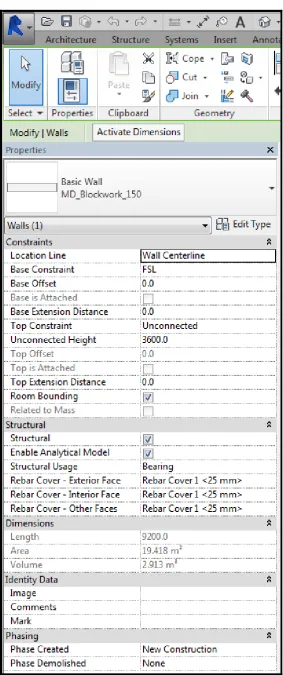
BIM software includes data and information regarding building elements and can include information such as height, length; wall type, area of the wall element, and whether the wall is load bearing. In addition to this, the model can include information such as the manufacturer of the material. The use of the BIM model therefore is not just for drawings for a project, it can be utilised as a 3D object database that contains the necessary information pertaining to each element within the model (buildingSMART-Australasia 2012). The information contained within the 3D BIM model, is the key aspect that sets BIM aside from other 3D modelling tools. Figure 2.1on the following page shows an extract from BIM Software Autodesk REVIT from the 3D model for a block wall element included in a building model. When the element from a specific area is selected from the model the properties of the element that are provided, includes the type of block wall, the length of the wall, the height of the wall, the area of the wall and the structural properties of the block wall:
Figure 2.1 - Properties of a building element in Autodesk REVIT (Source - Author)
2.3.2 BIM Tools and Workflows Overview
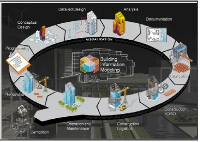
[image:28.595.87.501.214.507.2]The growth of BIM in the Architectural, Engineering and Construction industry has also meant changes to the workflow processes on projects. The use of BIM on projects now links all processes in a project which provides a synchronised approach to the management of the project throughout its lifecycle (Weatherford 2014). Rather than each process in the projects lifecycle being undertaken separately, all processes are now linked. The BIM workflow is illustrated in Figure 2.2 below:
Figure 2.2 - BIM Workflow (Weatherford 2014)
a. Clash Detection
Clash detection is a process of determining potential clashes in design elements, prior to the commencement of works onsite. Prior to the adoption of BIM the methods utilised have been through a combined process of overlaying 2D drawing layers to detect clashes, as well has 3D geometry checks from standard non BIM 3D models and also manual checks. Clash detection in the BIM model however differs from standard 3D model detection, as the design team is able run automatic clash detection in the model utilising predetermined selections. This enables clash detection to be run for example between the electrical and structural systems (Eastman et al. 2008).
In order for the BIM clash detection to be accurate, the BIM model must be a true representation of the project works. A study has been undertaken by Leite, Akinci and Garrett (2009) comparing manual clash detection completed in co-ordination meetings, and the use of automatic clash detection utilising the BIM model. The findings have determined that manual clash detection was able to detect clashes with the cable trays on the project, however automatic clash detection was unable to detect these same clashes as the cable tray was not modelled. The results highlight that if all building elements are not included in the BIM model, manual clash detection will achieve more accurate results.
In contrast to this, the design team on the Aquarium Hilton Garden Inn project that was delivered using the Construction manager at-risk method, implemented clash detection in the design phase. By implementing clash detection the design team uncovered 55 clashes prior to commencing works onsite. The detection of these clashes were estimated to have saved the project $124, 500.00 (Azhar 2011). This highlights the advantages to the use of BIM for clash detection, however the importance for the accuracy and completeness of the BIM model.
b. BIM Collaboration Tools
As a means to resolve the issues faced by project teams that have design and construction teams in different locations, cloud based BIM collaboration has increased in usage. Autodesk BIM360 is one such tool that enables users to upload BIM models for each discipline to the cloud. The models can then be accessed by any team member in any location, either on the construction site or the design office (Hardin & McCool 2015). BIM360 has improved the ability for project teams to utilise the BIM model collaboratively.
BIM products such as Tekla have also established collaboration tools such as Tekla BIMsight that can be utilised as a collaboration and communication tool by multiple design disciplines. For example the tool can be utilised to collaborate the architectural model with the steel detailing model, clash detection can then be undertaken between each of the models. The tool can also be utilised as the central platform for the entire project team to communicate with each of the design models for the project (What is Tekla BIMsight 2013).
c. Autodesk Revit Worksharing
The advancement of BIM tools now enable multiple users to be working on a central BIM model file for a project. In order to provide delineations between work zones in the BIM model, BIM tools such as Autodesk Revit establish Worksharing tools. Worksharing is an extension of the collaboration tools, where the 3D BIM design model can be modified simultaneously by multiple users (Vandezande, Read & Krygiel 2012).
d. BIM and Project Lifecycle Workflows
Recent advancements in BIM have seen the BIM model used in new dimensions, surpassing 3D. 4D BIM is a tool that is utilised in collaboration with the 3D BIM model, by the project management team to incorporate scheduling information into the BIM model. The 4D BIM model can be utilised to visualise the schedule of the project prior to commencing works onsite through simulating the construction sequence (Mubarak 2015). 4D BIM is further discussed in Section 2.4.
5D BIM tools are utilised to incorporate cost elements for a project into the 3D model. The 5D BIM model can be utilised to undertake project cost analysis and cost management for the project. New dimensions are able to be added to the BIM model; therefore as the BIM model progresses to the fifth dimension the cost information is added. BIM models created by the separate 4D and 5D BIM tools and used in collaboration with the 3D BIM model are considered part of the overall BIM model for the project (Mubarak 2015). Figure 2.2 provides an overview of each of the functions in nD BIM:
Figure 2.3 - – Summary of functions of nD BIM (Mubarak 2015)
As can be seen in Figure 2.3, additional BIM dimensions are now emerging past 4D and 5D. Due to the early stages of use of the BIM model for these dimensions there are no case studies available examining the performance of these tools, furthermore, there lacks consensus in the literature regarding their use as either sustainability or lifecycle management. As shown in figure 2.3 Mubarak (2015) allocates BIM 6D for use in sustainability, and BIM 7D for facilities management.
In contrast, 6D BIM software is available for use in lifecycle management. The 6D BIM model can be used to replace handover documentation provided to clients at the completion of the project. The model can contain all necessary data pertaining to the operation of the completed facility, and specifically details for each room of the new facility (6D BIM Models 2015).
e. Third Party BIM tools
The 3D BIM model is integral to the BIM process and can be considered the authoring tool in the workflow. Third party BIM tools enable analysis of the 3D BIM Model by parties within the project team. The 4D BIM and 5D BIM tools are therefore analysis tools that a distributed environment enables the use of separately from one another. 4D and 5D BIM tools are also therefore considered third party tools in the BIM workflows. The 3D BIM model is able to extract data specifically for the use in each of the analysis tools (Young Jr., Jones & Bernstein 2008). Figure 2.4 shows the integration of the central BIM 3D Design Model with BIM analysis tools:
Figure 2.4 - Enabling applications extract data from design models and provide valuable analysis and simulation (BIM Building Information Modeling A Supplement to New York Construction)
2.3.3 BIM Global Adoption Strategies
Various authorities around the world have taken steps to increase the usage of BIM on projects, with a goal to improve construction industries. These strategies include mandates implemented by various government departments, as well as government agencies. These strategies indicate that the construction industry worldwide is acknowledging that BIM usage on projects provides a considerable advantage.
A summary is provided of a select number of countries and the strategies that have been implemented.
a. United Kingdom (UK)
A country at the forefront of BIM adoption in the construction industry is the United Kingdom (UK). The government has identified the use of BIM to be a key tool to streamline the design and construction process. If team members work from the compatible systems construction costs can therefore be reduced, the Government of the United Kingdom has implemented requirements for the use of BIM on Government funded construction projects, which requires that the use of BIM must include fully collaborative 3D Models by 2016, which is Level 2 BIM (The Government Construction Strategy 2011).
There are a number of maturity levels that are used to describe BIM use in the United Kingdom, and the level of detail that they are used for. The use of the levels enables the construction industry to work towards targets with the goal to achieve BIM compliance. The levels are as follows (BIM levels explained 2014):
Level 0 BIM – BIM used in this level is limited to 2D CAD drafting, and uses no collaboration between the design teams.
Level 1 BIM – BIM used in this level includes 3D CAD and also 2D CAD, however there is again no collaboration of data between different disciplines. The model used in this level also contains no additional information, they are simply design models.
Level 2 BIM – the key aspect to this level of BIM is the collaboration between each party, and the sharing of the 3D models. Each discipline such as fire services, mechanical services, architectural and structural continues to use their own model, however through the use of common software; the files are able to be shared. The common software that the BIM model must be compatible with is Industry Foundation Class file formats and Construction Operations Building Information Exchange file formats. The use of these file formats enable the project team to combine the data from each of the building models in order to undertake evaluations of the models. This level of BIM also enables the use of 4D and 5D BIM.
Level 3 BIM – the usage of BIM in this level requires full collaboration between all disciplines, including the usage of a single shared model. This enables all disciplines to have access to the shared model, with the ability to modify as required. This level of BIM will also utilise the 4D and 5D BIM aspects of time and cost, which are described later in the literature review.
A BIM maturity model has been created, as a means to provide clarity and also define the Levels of BIM maturity from 0 to 3. The model provides a delineation between each of the levels, showing Level 0 as CAD only, with paper based tools. Level 1, as discussed, introduces 2D and 3D CAD usage, with file based collaboration tools. Level 2, which is the current target for 2016, introduces BIM and Library Management to the maturity level. The future, Level 3 is a fully integrated BIM model utilising a web based BIM Hub. It is this maturity level that introduces Lifecycle Management to the BIM model (A Report for the Government Construction Client Group: Building Information Modelling (BIM) Working Party Strategy Paper 2011). The model is shown in Figure 2.5 on the following page.
Figure 2.5 - BIM Maturity Model (A Report for the Government Construction Client Group: Building Information Modelling (BIM) Working Party Strategy Paper 2011)
The mandate adopted by the UK has seen an increase in BIM usage in the years from 2010 through to 2013, from 13% to 54%. Furthermore, for those organisations utilising BIM, 51% have achieved Level 2 BIM and 7% have achieved Level 3 BIM (NBS National BIM Report 2014). UK owners have also been drivers in increasing BIM adoption in the construction industry with a report completed in 2014 identifying that over 65% of owners in both the public and private sector require BIM to be utilised on their projects (SmartMarket Report The Business Value of BIM for Owners 2014). This highlights that owners have also identified with the advantages that the BIM mandates will bring to the industry. The mandates are therefore considered a successful strategy in increasing BIM adoption in the construction industry.
b. United States of America
The General Services Administration (GSA) in the United States of America is an agency that provides management to large number of property and construction for the United States Government. In 2003 the GSA implemented the mandatory requirement for 3D models to be utilised in the design phase of all projects that they funded. While the mandatory requirement is for 3D models there is also the expectation that the that the use includes the 4D time parameter also (Zeiss 2013).
The national 3D-4D BIM program was implemented to enable the GSA to provide better management techniques to meet the requirements for the construction projects. The policy has been established as a requirement for BIM to be utilised on all major projects completed for GSA. In addition to this, a requirement of the program is for BIM deliverables at each milestones of the project. A highlight of the GSA program has also been the implementation of a BIM Guide series to be followed (3D-4D Building Information Modeling 2015).
In contrast to the UK, BIM adoption in the United States has not been widespread for either owners or organisations. The findings of a report published on the owners requirements for BIM usage on projects in the United States, has identified that only 30% of public and 11% of private owners require BIM to be utilised on the projects (SmartMarket Report The Business Value of BIM for Owners 2014). This is significantly less than the UK, and can be attributed to the policy, not mandate, being specifically adopted on GSA projects, with a lack of a widespread mandate being imposed on the industry.
c. Singapore
Singapore is another country that has identified the potential advantages to improve productivity in the construction sector, through the implementation of BIM. Leading the way in the adoption strategies was the Singapore Building and Construction Authority (BCA) which is a department of the Singapore Government. 2010 saw the introduction of a BIM Roadmap, that set out a goal to increase the number of BIM users to 80% in the construction industry by 2015 ('All Set for 2015: The BIM Roadmap' 2011).
Mandates have been established in Singapore as a means to aid in the increase of BIM users. By the year 2013, all projects over 20000m2 were required to undertake Architectural BIM model e-submissions for all required regulatory approvals. In July of 2014, this increased to include Engineering BIM models for e-submission for projects over 20000m2. In July 2015, this again increased to require all BIM model e-submissions for projects with a Gross Floor Area over 5000m2 (BIM Factsheet 2013).
The Singapore Government has implemented a number of measures in order to promote and also support the adoption of BIM in the construction industry. These have included BIM competitions, seminars and also BIM manager forums. In addition to this, BIM guides and standards have also been published. This has led to an increase in the usage of BIM by organisations, with the findings of a survey undertaken on BIM usage in Singapore organisations showing between the years 2009 to 2013 there was a growth from 25% to 76% (SmartMarket Report The Business Value of BIM for Owners 2014)
A further example of the Singaporean Government’s move to increase BIM adoption in the construction industry is the establishment of a BIM fund that is utilised to support firms to improve collaboration capabilities. The fund can be used to cover training costs, consultancy costs, software and hardware, in an effort to reduce design errors leading to additional rectification costs (Technology Adoption: Building Information Model (BIM) Fund V2 2015).
d. Australia
The adoption of BIM in Australia has somewhat lagged behind other countries. Smith (2014) has reported that the adoption of BIM in Australia has been limited in comparison to other regions. While there has been an increased interest in the adoption of BIM in Australia through the implementation of initiatives, the Australian Government has not yet moved to introduce any BIM mandates to the construction industry.
A report on the adoption of BIM by Australian organisations identified in the year 2014 that approximately 50% of BIM users were utilising BIM tools on projects. Furthermore, the report established that of the BIM users, only 30% were utilising 4D and 5D BIM on projects. The predominant usage of BIM in Australia remains largely with engineering and architecture firms, rather than contractors (SmartMarket Report The Business Value of BIM in Australia and New Zealand 2014)
While there have not yet been any government mandates introduced in Australia, there has been significant moves to aid in the adoption of BIM in the construction industry. The National Specification System of Australia (NATSPEC) National BIM Guide has been produced in an effort to provide clarity to the all members of the project team of the BIM requirements for the project and also standardise the adoption of BIM on projects (NATSPEC National BIM Guide 2011). The BIM guide has been established in order to provide a standard on how BIM should be adopted and managed by the project team on a project. This includes establishing the BIM management plan, which defines the modelling considerations specific to each project, the responsibilities that are assigned to the Design Team BIM Manager, the author control of the BIM model, and the standards for the collaboration between the project team members with the BIM model. The BIM guide also provides standards on how the BIM file storage folders should be structured, to enable efficient use of the project files.
As a means to facilitate the adoption of BIM in the Australian Industry, a framework has also been established. The framework has identified a number of objectives to be utilised as a guide to further improve the adoption of BIM. The purpose of the framework was a method of resolving Australia’s fragmented approach to BIM adoption in Australia (A Framework for the Adoption of Project Team Integration and Building Information Modelling 2014).
2.3.4 BIM Contractual Challenges
The increase in BIM adoption has also seen a need for the review of the legal implications associated with its usage. The use of collaborative BIM