Pro2ram Visualization
in
Pro2rammin2 Environment
A thesis
submitted in partial fulfilment
of the requirements for the degree
of
Master of Science in Computer Science
at
Massey University
By
Shurong Dong
Department of Computer Science
Massey University
New Zealand
Acknowledgements
I would like to thank Professor Mark D. Apperley who proposed
and supervised the project. His support and encouragement has enabled
this thesis to be completed in the time possible.
Thanks are also due to Colin Engle, John Holley and other staff of
the School of Information Sciences who support computers in the
laboratory.
Thanks are also given to those lecturers and students who have
helped me with my English writing and helped me through the process
Abstract
Acknowledgements
1.
Introduction
1.1 Development of the Programming Environments
1.2 Program Visualization
1.3 Considerations for Program Visualization
2. Program Comprehension
2.1 Programs in the Large
2.2 Programmers
2.3 Program Comprehension and Manipulation through an
interactive interface
3. Current Display Techniques for Large Documents
3 .1 Techniques
3 .2 Interface Design Principles
4. Programming Environment
4.1 The Analysis of A Programming Environment
4.2 High Level Data Store and Processing
4.3 Current Development of Supporting Tools
4.4 Advanced Programming Environments
5. A Practical Prototype
5 .1 Features
5.2 Layout
5.3 Objects of the Source Code
5 .4 Macro Functions
5.5 Some Specifications
References
Appendix 1 :
Quick Use of HI
Appendix 2 :
A Simple Program for Testing
Appendix 3 :
Abstract Program
Appendix 4 :
Compressing One Procedure
Appendix 5 :
Compressing All Procedures
Appendix 6 :
Multiple Text Subwindow & Structure Diagram
Appendix 7 :
Comment
Appendix 8 :
A Complete Map of A Complex Program
Appendix 9 :
Map of A Simple Program Showing A Variable
Chapter 1
Introduction
A program is subject to modification during its life cycle. In order to modify it, the program must be easy to understand by programmers. This is particularly important during the maintenance phase of a software system life
cycle.
Software maintenance is a time-consuming task, and occupies most of the time in a software life cycle. Many factors influence the time taken for maintenance. These include the readability of the program, the complexity of algorithms, the available tools, and various other factors. For a very large and complex piece of software, an efficient and powerful environment that supports the interaction of the user with the source code would be of great benefit.
Until now, the main technique used to read and understand a program has been a mental simulation of computer runs, along with the reading of specifications. However, running a program does not give any sense of how a program is organized, nor how to modify and improve it. This is because programs are written for execution on a computer, not for reading. The comm~nts associated with source code are peculiar to the programmer who created the source code, and may be difficult for others to follow. There is a demand for a simple and standard representation of source code.
implementation of a prototype of a simple interactive programming environment
with a graphical representation of the program.
1.1 Development of The Programming Environment
1.1.1 Introduction to Programming Environments
The earliest programming environments were concerned only with the
communication between source code and the computer. The user told the
computer how to do the tasks, not simply what to do. As techniques in
computing developed, the languages used, from assemblers to high level
languages, became more understandable by humans. Facilities included
operating systems, debugging tools, text editors and so on, and became more
and more powerful and efficient. These assisted in the interaction between the
programmer and the code.
Command and batch oriented systems are a poor match for the human
cognitive system, which is very visually oriented and computes incrementally.
So people began to realise the need to improve the user interface and its
performance, and developed data oriented systems. A data oriented system is
one in which users interact directly with system data, instead of using a complex
set of commands.
The "Smalltalk" system developed at the Xerox Palo Alto Research Centre
[Goldberg, 1983] is an interpreter for an Object-Oriented Language based on
message passing. "Smalltalk" is extremely good at application prototyping. It is
not only a programming language, but also a programming environment. It
successfully uses a window-based graphic display system to reduce complexity.
There are many other environments created on the basis of "Smalltalk", which
use a high resolution display with more powerful interaction provided by the use
of graphics or multiple views of a program.
1.1.2 Proposed Development
The goal is to develop a unified programming environment that stimulates
program conception at a high level of abstraction, promotes programming by
to be displayed in multiple views while editing programs, and provides extensive diagnostic facilities during program execution. This can be achieved by
providing programmers with more powerful tools to cope with the increased
complexity of modem systems. Such tools will enhance the interaction between
programmer and code.
To achieve this goal, the source code should be considered as a structured
database which is one of the objects in a vast space - that is the programming
environment implemented on a screen. In the past, what a user could see was the
source code only. Now, as a whole, source code is just one of the objects which
needs to be analysed and manipulated visually. Other objects in the space are
tools that users can use to act on the source code database. These tools include a
compiler, a debugger, a run-time tool, those which support the environment
such as icons and windows for text and graphics, and also control objects, such
as a mouse, cursor, menus and buttons.
The environment not only has to provide for all queries the user may want
to make of the source code database but also to call related tools to give the user
the proper feedback.
1.2 Program Visualization
Glinert has drawn a destination between visual programming and program
visualization [Glinert, 1990]. Visual programming refers to the use of graphics
to define or to help define programs. The purpose of it is to make programming
easier. PV is the use of graphics to make programs, and their execution,
understandable.
Some high level languages are similar to natural language in order to be
more understandable. The higher level the language is, the more complex the
grammar will be. Even though programming language can be made the same as
English grammar, this is still impractical because people do not all speak in the
same way. So a formal programming language is still needed in writing. On the
other hand, to understand a program, users should be able to read it in the way
which they think they can understand it the best. This requires different kinds of
language to different representations will be a great help for users to understand
the program.
Program visualization can be used in teaching algorithms, complex data
structures, program debugging, algorithm design and so on. It is used to support the basic and particular needs of users. The primary needs of a
programmer during development and maintenance are getting information,
finding the relationships between data (i.e source code or tools), and viewing
objects in different ways [ Rajlich, 1990].
1.3 Considerations for Program Visualization
1.3.1 Type of Information
One problem with program visualization is how to represent different
types of information. The information can be as small as one character or one
symbol, and it also can be as large as a graphics with many times screen size or a
document with thousands lines. Information type can be anything which is able
to be shown on the screen. The designer have to choose the most useful and
important ones in order to make the interface clear and efficient.
For example, in a map, how should a procedure be represented? Are
variables local or global? Which information is static, and which is dynamic?
How should feedback on correct actions be provided to the user? All the
information has to be presented in a suitable way and it should be consistent. For
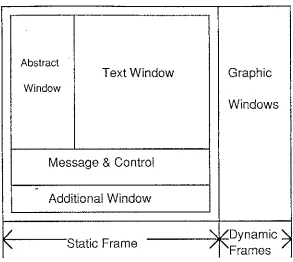
example, the static information, which should always be shown in a particular
place such as the main frame, includes the text window, abstraction window,
message/control window, and an additional window(see Figure 1.3.1). In order
to distinguish the main frame from other frames, the main frame can be defined
using a double outline, while others can be single outlines. Different types,
Abstract
Text Window Graphic
Window
Windows
Message & Control
.
Additional Window
/
'
/Dynamic~'
Static Frame / [image:11.596.127.420.53.315.2]Frames
Figure 1.3.1 Different Information in Different Windows
Figure 1.3.2 The Complexity of A Map
[image:11.596.119.412.373.638.2]1.3.2 Map Size and Complexity
A map is a diagram which shows the relationship between procedures in a
program, and is used by programmers as an aid in understanding the program.
For a small program, programmers probably view a map in one or two views.
When the program is very large, i.e. the number of procedures is about 100 or
more, the map to represent the structure will be very large and complex. In these
cases a clear, comprehensible, and well designed map is needed. Figure 1.3.2
shows an example which is part of the map used in the prototype introduced in
Chapter 5. Although the map has been simplified, it still appears complex even
to a moderately sized program.
1.3.3 Speed
The generation of a map should be fast enough to be used in practical
situations. During programming, interactive formatting and syntax checking can
take some time. If the time delay is too long, users will be dissatisfied no matter
how good the interface looks. In a graphical environment, many of these
operations are slow. Algorithms to accelerate the creation of a map are currently
being studied by others.
1.3.4 Limited Screen Size
Screen size is the bottle neck between human and computers. How can all
of the information be displayed? What information is more important, and
should the user make use of tools? Such problems have been considered for a
long time by many people and still exist. With the spread of applications of
computers, much more information needs to pass through the size-limited
screen. Although the screen size can be enhanced or several computer screens
can be used at a time for one task, the cost is very high and some others
problems emerge, such as the inconvenience of multiple screen views, and
difficulty in concentrating on one particular point on a very large screen, which
may be beyond the direct control of humans.
On a size-limited screen a well designed interface is essential. But
designing a good user interface is not easy. Nothing can satisfy all the people for
all tasks, and not all techniques can be used on all computers. Designers should
Chapter 2
Program Comprehension
It can be difficult for a programmer to understand large programs. The
following discussion looks at this problem, and examines how programmers
relate to programs. It also looks at techniques for assisting programmers.
2.1 Programs in the Large
2.1.1 Creating and Understanding Large Programs
Most programs are created using text editors. A general text editor is
usually sufficient for a small program. For a large program, the editor may have
a special display format for a particular language and it may provide error
checking while editing. However users find this is not enough for a very large
program. Analyzing the structure of a large program is one of the most
frustrating parts of software maintenance; it takes a lot of time.
In creating a program, the time for a single cycle is generally long from
editing to compiling and sometimes execution. There are always some errors in
compiling or at run-time. Some methods used to limit error occurrences in
editing such as highlighting reserved words, symbol matching and so on, help
programmers to work more quickly and correctly. There are also some
techniques which can be used in compiling. For example, one large program can
be divided into small subprograms which are compiled separately. In this way,
errors can be found and corrected immediately and easily.
To understand a very large program is not an easy job, but this has to be
done in the maintenance phase of the life cycle of a software product. A program
maintainer must have an understanding of the whole program before reading it in
more detail.
Program abstraction systems and program structure analysis can be a great
is no efficient tool for programmers to comprehend the program in this way. Maintainers can understand the program only by reading the specifications at the
first stage, but they still do not know how the program is structured before
reading it closely.
2.1.2 Program Analysis
Large programs, may comprise many subprograms linked together. These
will often be produced by more than one programmer. Each subprogram is
independent and may be written in a different style, so the links between
subprograms and links between procedures in one program are very important in
creating a large program.
Inside a large program, some key parts exist. Such as global control
variables, main flow function calls and basic statements of a function. These represent the core of a function or program, and also they show the relationship
with other modules or functions. Experienced programmers always try to find these focus points when they read a program. Although the other parts of the
program are also necessary, focusing on the key points enables programmers to
get the main idea of each part immediately. Some current interactive techniques,
which will be introduced later, enable key parts to look more obvious than other
parts.
Different languages have different formats. All programming languages
are not represented in the same way, but there are some standard tools which can
represent a particular language in a common way. People will understand the
structure of the program by reading the representation just as they understand the
details by reading the source code. This structure is the abstraction of large
amount of basic data. It takes less space and users can find where they are
quickly.
Other information about a: program can be considered, such as where it is going to be used and what the result of the application is. These information are
2.2 Programmers
The first real study of human factors in programming appeared in 1980
[Shneiderman, 1980]. Gradually, this work grew from concerning student
programmers to experienced programmers, and from small programs to large
programs. By understanding how and why programmers do a task, it is easier to
make prescriptions that can aid programmers in their task.
Programmers can be the designers or maintainers of a program. There are
demands for designers to have not only a simple and complete language, but also
a powerful programming environment which enables them to work creatively
with fewer mistakes. To help the maintainer to comprehend a program, it is
necessary to be in a good position to recommend changes in documentation
standards that would enable the maintainer to more effectively glean from the
documentation the necessary information. This implies a more understandable
representation derived from the program. This representation can be in any form
provided it is helpful to understanding the program.
Both designers and maintainers think about a program in two ways. One is
bottom-up, the other is top-down. Bottom-up design is generally used in
creating small programs. The programmer studies and interprets small groups of
stateJJ1ents and stores the interpretations in his or her memory. The top-down
method is used with larger programs so that the programmers can organize the
structure beforehand and then create individual parts.
It is easy to create a program when the programmer has the basic idea of
what the structure will be. Otherwise the program will become longer and
longer, and the programmer will forget how it is structured. They have to reread
the source code line by line to find out what it means and where it can be
changed. Having the program structure represented visually is not only helpful
in creating programs, but also useful for maintenance. Without the idea of the
whole structure of the program, sometimes it is even harder to read a program
than it was to create it in the first place, and it takes a longer time to understand
The study of programmers is still in its first steps. It is not only necessary,
but also important. Working on computers is an art created by human beings,
not just the carrying out of tasks that programmers should and should not do.
2.3 Program Comprehension and Manipulation through an interactive interface
The human computer interface is the window through which humans and
computers communicate to each other. A user can get much benefit from a well
designed user interface. It enables the user to be in control of the system,
encourages the user to try anything with few errors, and users can learn very
fast.
A program is understood by reading it in a certain environment. The
environment contains a user model, command language, feedback and display.
Figure 2.3.1 shows a common used environment for editing a text file. The user
model may be a form of text editor which contains the source code, and some
tools. It is the framework which provides guidelines for applying techniques.
The command language is the set of operations that can be carried out on the
objects in the model. These operations may involve dialogues, commands, menu
selections or direct manipulation. The feedback is much more important in an
interactive environment than in other environments. It is not only the feedback of
the commands but also the visualization of the structure and content of the
program source code. More attention must be paid to the display for large and
File Edit
-□
Finding ...A program is un Spelling ··· ding
feedback and display. The user model
may be a form of text editor which
Figure2.3. l A Common Environment
::, ... :::
A few models have been proposed for program comprehension.
Shneiderman and Mayer [Shneiderman, 1979] created a largely bottom-up
model. According to this model, the programmer reads and interprets a program
using the bottom-up method. New information will be understood on the basis
of what the programmer thought earlier. Eventually by this incremental process,
the whole program, or as much of it as possible, is comprehended. A similar
model proposed by Basili and Mills [Basili, 1982] rejects the idea that a program
is understood on a line-by-line basis. However, both methods are basically
inductive and are driven by the data of the program text.
Brooks [Brooks 1987] proposed a model which can be considered as
top-down process. The program is understood first by reading the specification,
understanding the functions and guessing the structures. According to this
understanding, the program then can be read in more detail.
No matter which model is used, the emphasis is always on the
understanding of the source code. Consider the source code as an object
composed of other objects in different levels. The simplest object is a character.
A word is composed of characters. A semantic line is composed of words and
symbols. Lines are grouped together as procedures and then programs. A line is
the smallest unit for grammar checking. The most immediate feedback in editing
of errors. Placing a line with correct grammar in the right position using
indenting· techniques makes the program structure more clear and
understandable.
Different operations are used on the different kind of objects identified
above. Dialogue boxes are slow and are only used in some situations. Menu
selection is simple, flexible and there can be no command grammar mistakes.
But this method is also slow and it can be difficult to find the correct submenu.
For experienced users, command-based interaction may be more efficient. The
feedback required for an operation includes the correctness of an action, the start, ongoing and the end of the action, and also the effects of an action. The
information for correcting errors, and the visual display of changes, are required
in an interactive environment.
A model is the way to read a program, it is supported by the available
display techniques and tools. The display techniques and tools enable
programmers to read a program in multiple ways. By many experiments,
graphics is more understandable by humans, while the display is central to
Chapter 3
Current Display Techniques for Large Documents
Techniques for the effective display of information have received attention
since the earliest use of the CRT. The earliest computer graphics displays came
out in 1950. In the last 10 years, various kinds of display techniques have appeared. With the development of computer and electronic techniques and the
reduction in cost of graphics devices, display techniques have been widely used to increase the quality and productivity of computer applications.
3.1 Techniques
Most techniques currently used for display are based on two basic
concepts. One is data abstraction, the other is structuring. Abstraction covers
information hiding and high level presentation, while structuring deals with the
relationship between objects. Data abstraction makes the structure clearer and it
reduces the complexity of the display. From the following techniques derived
from these two methods it is possible to identify more special features that
contribute to the interface display. Most of these can be implemented on
graphical terminals.
3.1.1 Scrolling
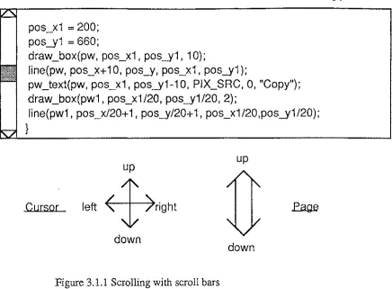
Scrolling is a common viewing technique which enables users to view the
content in a window continuously. Generally, it is realised by pressing the
cursor up-down-left-right or page up-down buttons on the keyboard or by
scrollbars visually (see Figure 3.1.1). The position of the rectangle in the
pos_xi
=
200;pos_yi
=
660;draw_box(pw, pos_xi , pos_yi , i 0);
line(pw, pos_x+ i 0, pos_y, pos_xi, pos_yi );
pw_text(pw, pos_xi, pos_yi-i0, PIX_SRC, 0, "Copy"); draw_box(pwi, pos_xi/20, pos_yi/20, 2);
line(pwi, pos_x/20+ i, pos_y/20+ i, pos_xi/20,pos_yi/20);
}
Cursor
up
left
4,ight
[image:20.597.104.541.57.378.2]down
Figure 3.1.1 Scrolling with scroll bars
3.1.2 The "Fisheye" Display
up
down
In daily life, people are always interested in some particular things, and
ignore others. For example, consider the representation of a map, the world map
or street map for a local area. Some people are interested in the names of
countries, some are interested in geographical layout and some want to see the
special people of each area or get the information of products in each part of the
world. All of those aspects of interest can be the key points which a "fisheye"
view focuses on.
The "fisheye" view was proposed by George W. Furnas in 1986 [Furnas,
1986]. He suggested that it might be useful for the computer display of large
information structures like programs, data bases, online text, etc. In viewing a
..
large system through a size limited screen or window, it is always difficult for
users to find the right place quickly by scrolling or other scanning methods
because all the information is of the same importance, only a part of it can be
seen and users have no idea where they are.
The "fisheye" technique, which is widely and naturally used in life, can
been used on hierarchical file systems and menu access systems, hierarchically
organized· text, graphic display and structured programming languages. With
different algorithms, the view can also be used in different disciplines by seeing
in different ways. It focuses on one particular part like keywords or what the
user thinks is important. It is especially used in the representation of large and
complex information spaces.
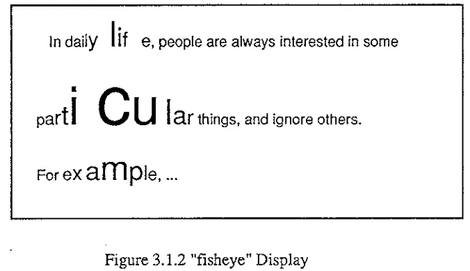
According to the "fisheye" view theory, the view is created from two
aspects; one is the importance of an item, the other is the distance between the
focus points. The data which is more important to the user or nearer to the focus
point will be shown in more detail. There is a simple example which is shown
below:
In daily
I
if
e, people are always interested in some•
part
I
C
u
I
ar
things, and ignore others. [image:21.596.126.464.294.489.2]For
example, ...
Figure 3.1.2 "fisheye" Display
In this example, "c" is the symbol a user wants to find out and understand its place or other information about it in detail. Those characters which are near
"c" are larger than those far from it. The distance affects not only in horizontal
but also in vertical.
Although users can get some important information immediately, it is
impossible to catch all that they_ need. The larger the range is, the less detail the
display can provide. Also in one view, users cannot see the detail in two separate
parts which are far apart, for example, in comparing the geography of two
3.1.3 The "Bifocal" Display
Instead of viewing objects continuously from detail to less detail, "bifocal"
display [Apperley, 1982] focals on two parts: one is the detailed part, the other is the less detailed part. For example, consider reading a record which keeps the
path of countries a person travels around the world. Instead of reading all the
details in each part, readers may want to read one part in detail and scan other
parts. By using "bifocal" display, readers can read any travelling record in one
country and find out from where the traveller goes to the country and where he is
going to.
"The key concept of the "bifocal" display is to focus on the area (of the
data space) of interest, rather than to window on it, so combining an overview of
the entire data-space with a detailed view of a small portion of the space. The implementation of the "bifocal" display can be achieved by providing three
separate viewports, each with an individually programmed origin which can be
moved continuously through display memory. [Apperley, 1982]"
There is an example which shows how a "bifocal" display is different
from the conventional display (see Figure 3.1.3).
Travel Diary
1 1 1 1 1 1
9 9 9 9 9 9
8
8
8
8
9 96
7
8
9 0 1Travel Diary
1 q 8 q
1
1
1
s
A
NF
1
1
I u e I
9
9
9
9
9
ns
w
J
~
t
rz
I8
8
8
g
r
e9
9
r
7
8
r I 01
6 e a a
8
(b) A "Bifocal" Viewing System - Level 1
Travel Diary New Zealand
1 1 1
1 1
une
9 9 9
1.
***********9 9
8 8 8
9 9
6 7
8
2. *********** 01
(c) A "Bifocal" Viewing System - Level 2
Travel Diary
1989
***************************
* * *
***************************
1990
***************************
[image:23.597.152.452.61.232.2](d) Conventional Viewing Window
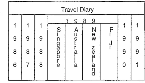
Open the record of year 1989 from the top level abstraction of a travel
diary ( see Figure 3.1.3(a) ). Figure 3.l.3(b) shows the countries in record in
the middle viewport. Other years go to two ends. By choosing one to see the
detail, other countries go to the ends as well ( see Figure 3.1.3(c) ). Those years
and countries which are not in the central viewport can be easily dragged to the
middle when they are required. Figure 3.1.3 (d) shows the conventional viewing
window in which the text is in one level. Users can only see the screen size
contents.
Like an amplifier, the "bifocal" display amplifies the middle part of an
object, while the leaves the two sides as before. No matter where the amplified
part is, it always remains in context. It is easy to drag other information to the
central viewport. For the object in the viewport, there is detailed information
about it, and there are relatively high data abstractions of those details. The
information at either end, which is far from the current viewport, can be moved
quickly to the central viewport by moving the objects at high level.
3.1.4 "Hypertext"
"Fisheye" and "bifocal" displays are for viewing objects continuously in a
sequence. Whilst it is hard to get logical related parts immediatly for a large
object.
Large complex programs are different from small simple programs in
many ways. They do not just have different amounts of data, but also different
kinds of links, display formats and storage formats. They need to consider the
screen size, as well as speed and convenience of retrieving data. In the past, the
data to be physically linked was put together. To find a particular place, users
had to remember line numbers or page . numbers, which can be very easy to
forget. It is impossible to remember several logic relations of one object or one
kind of relation of all associated objects. Generally, users use scrolling to find a
place, which is very slow for a large program. Logic links enable users to get the
relative information immediately. The links between data are shown in a high
level data abstraction which can get rid of very detailed information. It frees
users from trying to remember the places of all sorts of information or spending
too much time on finding the places which obviously interrupts the user's
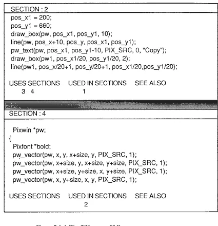
Figure 3.1.4 is an example which shows the links used in "Hypertext".
There are· two kinds of windows; one is active in which the contents are
generally the indexes, the other is additional. Positioning the mouse pointer on a number in the indexing information for a section and clicking has the effect of
overwriting the text in the other window with the chosen section.
SECTION :2
pos_x1
=
200;pos_y1
=
660;draw_box(pw, pos_x1, pos_y1, 1
O);
line(pw, pos_x+10, pos_y, pos_x1, pos_y1);
pw_text(pw, pos_x1, pos_y1-10, PIX_SRC, 0, "Copy"); draw_box(pw1, pos_x1/20, pos_y1/20, 2);
line(pw1, pos_x/20+ 1, pos_y/20+ 1, pos_x1/20,pos_y1/20);
USES SECTIONS USED IN SECTIONS SEE ALSO
3 4 1
SECTION :4
{
Pixwin *pw;
Pixfont *bold;
pvy_vector(pw, x, y, x+size, y, PIX_SRC, 1);
pw_vector(pw, x+size, y, x+size, y+size, PIX_SRC, 1 ); pw_vector(pw, x+size, y+size, x, y+size, PIX_SRC, 1 ); pw_vector(pw, x, y+size, x, y, PIX_SRC, 1);
USES SECTIONS USED IN SECTIONS SEE ALSO
2
Figure 3.1.4 The ""Hypertext'"' Browser
USES_SECTIONS denotes all the other sections used by this section.
Such as the procedure in section 2 in the upper window calls draw_box
procedure which is in section 4 in the bottom window. On the other hand,
USED_IN_SECTIONS indicates the sections which call the current procedure.
The draw _box procedure in section 4 is used in section 2. SEE_ALSO is another
20
listed under SEE_ALSO. For example, draw _box function, draw _circle function
and so on.
Although "Hypertext" makes it easy to get a related section, it is still
difficult to know how all the sections are connected and how to get other
sections quickly. According to the experiment of comparing "Hypertext" with
the techniques [Monk 1988], it has a significant improvement of performance by
using "Hypertext" with a structure map. The user not only can see where to go,
but also where he or she is going.
3.1.5 "Folding"
The data necessary to describe the structure and behaviour of a large
system is far too complex to be displayed entirely. Data that is necessary for the
user is scrolled off the screen and lost. This makes a complex system harder to
understand. There is the need to filter out necessary information and only this
useful information is shown on the screen.
For a large document which needs to be read in one view, such as a
procedure in a program, there is a demand for a large screen. However, the
screen can not be unlimited. To process a large document with a limited screen,
it is not possible to view all the detailed information simultaneously. It is necessary to cancel some information which is not important at the moment, and
make the important information more obvious. '"'Folding"" is a technique for
hiding some portions of a piece of text, leaving only those sections which are
important. ""Folding"" is different from other techniques in that it does not show
the unimportant parts at all. ""Folding"" makes the display clear and simple.
""Folding"" also helps users to understand the whole text quickly. For
example, each book has a table of contents. Readers always get first feeling
about the book from the introduction and the table of contents. The same applies
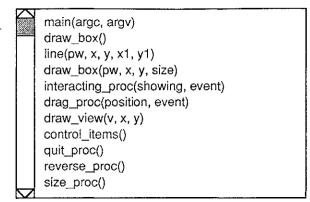
to analysing a program. Figure·".3.1.5 shows the procedure names of a program
main(argc, argv) draw_box()
line(pw, x, y, x1, y1) draw_box(pw, x, y, size)
interacting_proc(showing, event) drag_proc(position, event)
draw_view(v, x, y)
[image:27.597.152.462.56.258.2]control_items() quit_proc() reverse _proc() size_proc()
Figure 3.1.5 ""Folding"" Display
The headings of procedures are all taken from the program itself. Showing
headings and "folding" detailed contents are not something new. Users find it
easy to get use to this. It greatly reduces scrolling time, offers a large range of view and enables the direct manipulation to objects in different levels.
3.1.6 Browsing with Different Techniques
Many display techniques are available, but not all techniques are suitable to
all interfaces. Different techniques have advantages or disadvantages with
different tasks.
For example, to compare some feature of two countries which are very far
away on the map, it is impossible to use scrolling because the map is too big to
put in one view. There are also similar problems in using "fisheye" view
technique unless comparing between all the countries. The possible solutions are using "folding" or "Hypertext" techniques. By "folding", two countries can be
put together physically while with "Hypertext", there can be other windows to
meet the needs of particular use.s. Also the "folding" technique is not good for
reading information which has an effect on other parts around it.
"The different browsers constrain which sections can be simultaneously
visible in different ways. The scrolling browser constrains a user to viewing
sequentially adjacent sections. A user of the "Hypertext" browser can only view
sections which are adjacent in the "Hypertext" space i.e., each of the two
'see also' indexing information. A user of the "folding" browser is
unconstrruned as to what sections are open at the same time. There are also
different constraints upon the way a user can move about the program. It might
be thought that the "Hypertext" browser will require many more operations to
reach some required state than the "scrolling" or "folding" browsers. This is not true because the 'uses'/'used by' hierarchy is very shallow and in addition there
are the 'see also' links." [Monk 1988]
Several of these display techniques have been used in the programming
environment which is described in the next chapter.
3.2 Interface Design Principles
Many techniques and tools are available for interface design. There are no
definite rules because there is no general purpose interface, perfect for all
environments. However, some methods are helpful for displaying information in
the most efficient way. The ability to express the same kind of data in different
ways offers users more flexibility. In addition to those display techniques
below, there are some measures which should be available in the system; such as
"undo", on-line specifications and so on.
3.2.1 Layout of the Interface
Generally screen size is limited. So consideration must be given to where
and how information should be placed and how much can be placed on the
screen before it becomes cluttered. Both information and control objects have to
be shown on the screen, even further limiting the space available. Conflict is
generated by the different kinds of information that might be displayed, and the
space allocated to them. This requires careful consideration in designing the
layout. In order to show more information, each display may have to be
abstracted or only a small part may be seen in each view. One area of the screen
may be dedicated to a particular type of display, which can be used for different
information scrolling, etc. Some information need not take up static space all of
the time, and need not be considered in the basic layout.
Multiple display windows are used on high resolution display screens.
same time. No matter whether the information is divided logically or physically, the multiple display window technique can represent it clearly. Windows can be
folded, closed or open, and each window can be called quickly by changing the
current control.
To make good use of screen space, it should be possible for users to
control the layout themselves. The position of an item of information, the size of
a window, the different views of one object and the type of representation are
variables. They can be adjusted or changed according to the user's needs and
habits. Window techniques are currently widely used. They are considered to
provide flexibility to users.
3.2.2 Data Abstraction
What an object looks like influences the interface heavily. An icon can
represent a system file, a user file or a tool. As abstractions of those data, icons
express some meaning of the data though this may not be very accurate, and
there are no links shown among data which would be easy for users to see the
relationships between them.
Different geometric shapes, colours, line shapes, line widths, light and so
on can be used to distinguish objects. It is better to use several distinctions rather
than ope. For example, if only colour is used to distinguish many different kinds
of objects, it is difficult for users to remember the meaning that each one
represents.
3.2.3 Type of Information
What the interface looks like depends on what kind of interface is suited to
a particular class of user. To experienced users, not all kinds of information
need to be static. The basic layout can only consider those that are the most
important. The more experienced the user is, the less the static parts in the basic
layout are on the screen and the more information can be held in the
environment. Static menus are clear and easy, and provide guiding information
which is helpful for inexperienced users, but not always necessary for others.
Only dynamic and continuous feedback can immediately meet the
need not be considered in the basic layout. The appearance point, when an object
appears, should be designed to be consistent. On the other hand, these features should be able to be changed, such as repositioning, resizing, giving an
appropriate label, and so on.
3.2.4 The User Interface in Applications
The user can not expect to do everything through one interface. Most of
the interface is designed for a particular environment in order to make it more
powerful in this particular area. This is also easier to implement. No matter what
kind of interface it is and what techniques it uses, independence from the
practical task is necessary. The division of an interactive system into several
layers was suggested by M-R Koivunen [Koivunen, 1988]. With the idea of
layers in an interface design, applications become simpler, because no interaction
modes or states are needed. Applications programmers can concentrate on the
Chapter 4
Programming Environments
The problem in creating a programming environment is how to combine
multiple techniques and devices to meet the needs of the particular task. An
effective interactive environment is one in Which a user carries out his or her
work with minimal conscious attention to how to use the tools. It should be one
easily controlled by a user to do his or her task with maximum effectiveness.
4.1 The Analysis of A Programming Environment
For a structured program, it is easy to show the structure as a graphical
view. In addition, to read a program in totally different ways, such as maps or
structure charts, the program source code itself should be readable and
understandable. No matter what kind of data types or what level of objects, no
matter whether it is a variable or an application program, they all have to be
meaningful and consistent.
In an Object-Oriented Programming Environment, editors can be designed
to highlight the objects in programs (procedures, variable names, or keywords),
instead of merely dealing with strings of characters. When writing the source
code, a syntax-directed editor can guide the programmer to create syntactically
correct programs by offering a choice of permissible structures as templates.
4.1.1 Variables
Meaningful and distinctive mnemonic variable names are helpful in the
understanding of a large program. Also, names can be hierarchical, denoting the
range used and the function. For example, an external global variable name can
be composed from program_name, usage and range, as
program-name _ usage _range .
For a local variable, the procedure name can be part of thename.
All variable declarations (object parameters) can either be shown in a
symbol table or separately. This is the basic information about a variable. The
26
used for control in a program. An understanding of variables would be a great
help in understanding the program. Up to now, not enough attention has been
paid to the role of variables by users, except the declarations. A diagram which
shows the control by variables would be useful.
In an interactive programming environment, the types or values of
variables or constants can be defined or changed at any place during
programming; perhaps even during the execution, if this technique is possible in
the future. Variables having temporary values at run-time will have more control
over the execution. This can be implemented by combining a compiler and
run-time controller. Two dynamic arrays are created to contain variables and their
values. One is for global variables, the other is for local variables[James, 1987].
This information can be viewed through a window which contains any variables
users need to know (see Appendix 9).
4.1.2 Phrases
Phrases are dynamically defined as objects. They can be the component of
some statements. For example:
if (condition)
then (statement)
else (statement )
Each part i.e. "if (condition)", "then (statement)" or "else (statement)" is
called a phrase. Each phrase is regarded as one object. Some editors allow users
to input any characters during editing, and point out mistakes in compiling. With
a syntax-directed editor, each phrase should conform to the permitted grammar
of the particular language. For example, the matched"(" and")", "else" can not
follow "if' but "then" and so on. The strategies of indentation and highlighting
the reserved words of these phrases are useful ways to read the source code as
shown above. Because the reserved words are highlighted, it is easier to see the
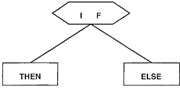
A structure diagram can be suitable for showing the structure of phrases in
a procedure, as shown in figure 4.1.2.
F
[image:33.597.166.460.130.275.2]THEN ELSE
Figure 4.1.2 Structure Diagram for Phrases
The structure in one procedure is different from the whole program; the
statements are organized logically. Structure diagrams can clearly describe the
logic. Figure 4.1.2 shows one kind of physical implementation. "What makes a
diagram look good?". Several factors were proposed by Ding and Mateti [Ding,
1990]. For a large system, complexity is one of the most important factors. For
a large program, phrases not only make the diagram simple and clear, but also
keep the semantic meanings. A phrase can be selected by double clicking the key
word of it (the middle button may be used since double clicking with the left
button is generally used for selecting a word if more than one button is
available). As in the last example, double clicking "if' with the middle button
will cause "if (condition )" to be selected. Triple clicking may also select the
whole structure which includes the "if' phrase and "then" and "else" phrases.
The functions can be acted on a phrase, both in the source code and in the
structure diagram.
With a diagram, users can not only easily understand the contents of the
procedure but also find out the errors of structure or unmatched symbols easily
and clearly. Combining this information with the error message, the user can get
the proper feedback which shows the position of the errors.
4.1.3 Procedures
A program is composed of procedures. Program views are visual
28
procedure is a node when the program is shown graphically. Links show the
relations between those nodes [Frank, 1987]. Multiple windows enable each
procedure to be edited separately. Users will feel safe to act on one procedure
without influencing others.
The data in the procedure, such as procedure_name, can be stored in a tree
in order to be retrieved and manipulated more quickly. The structure map of the
program derived from the tree gives users a structured overview of the program.
It helps group members or others to easily understand the program. A good
procedure name will have the same usage. It can be defined as program-name usage which is consistent with variable names.
A procedure can be focused on by creating a multiple text window which
displays only this procedure. A procedure content can be compressed or
extended. Users should be able to get the information about the procedure, such
as its main function/usage and where it is used in the program. The information
can be shown in text or graphical form.
4.1.4 Comments
Comments are used to help programmers understand parts of the program;
generally, a line, a procedure, or a subprogram. Comments can be written along
with tlJ_e program or in a separate file and can be represented in different ways
inside a program [Ronald, 1986]. They also can be embedded in the diagram or
under a menu. Different users prefer different ways. For example, figure 4.1.2
shows the comments for a line and a procedure. The problem is obvious. The
top message separates this procedure from the procedure above, and the
comments in the middle separate the lines of the program when the source code
line is long. Figure 4.1.3 shows the comments stored and shown separately.
Users can store as much information as they like without influencing the source
code. The comments in figure 4.1.2 can be associated with a menu or a function
/* This procedure will locate a position as the top point of a fixed sized view area by clicking on the screen with mouse*/
void
drag_proc(position, event) Canvas position; Event *event;
int pos_x, pos_y;
pos_x
=
event_x(event); /* Get x cordinate of the event*/pos_y
=
event_y(event); /* Get y cordinate of the event*/if ((event_id(event)
==
MS_LEFf) && (event_is_down(event))) ( /* Click with left button*/ if ((view_x != pos_x) II (view_y != pos_y)) {~ /* Draw view box if view point has
} }
}
1 changed*/
draw_view(-1, view_x, view_y); view _x
=
pos_x;view _y = pos_y;
[image:35.600.124.467.80.694.2]draw_view(l,pos_x, pos_y);
Figure 4.1.2 Comments in a Program
(Part of the Program in Appendix 2)
"' I/define NUMBER..SUN_VIE..,_..,QROS 16 lldef i ne NIJMBER_ST ANDARD_FUNCTION 20
This is a procedure used io ·call an new file~
get a f'1le name solection then load f'ile .•
press_ev
1 .
J_f_ind_e ,
===========,;;===s~"""'=Uli-used_ev 1
ile Quit
teHtsw., usedsw; tty;
panel, panelb, panelt;
ful saved
-~-f-~ l~i.st} (co1npress} [ Extenc1 ] ( find ] Help !_ Jou:::-.all]
[image:35.600.136.398.443.687.2]Also, comments can be a simple specification or a detailed document. This
varies according to different levels of information. Parallel to the program,
comments also should consider hierarchy, information hiding and data
abstraction.
One aspect is usually ignored by programmers, that is the updating the
comments. There either should be an indication that changes have been made or
they can be updated automatically.
4.1.5 Programs
Generally, a program is a file, and can be processed by the operating
system. It is always an independent task which can be called separately. For one
task, different programs with different styles enable the more flexible integration
of tools. One program with different parameters is another way of file
organizing. Which method should be used depends on the application. A
structured program can be shown in a tree format or a network diagram.
A processed program can be stored in another file. For example, a
compressed program, which contains only procedure headings and parameters,
is a brief view of the program. This dynamic information can be used for a quick
search of procedure names. Searching is much slower when reading a large
program than when reading a small and sorted one. Appendix 3 shows the compressed file of the program used in Appendix 2.
4.1.6 Display Strategies and Comprehension of Different Objects
For each dynamic object there is an inner code. It can be named by
combining time in sequence, function code and information level. Showing or
hiding is one of the parameters of the object. The parameters of an object define
what you can do to the object. For example, a procedure of a program can have
some parameters - compressing/extended, multiple text showing, structure chart
on/off and the position in the main source code text window.
Procedure names play an important role in understanding the source code.
If a procedure is thought of as an object, a good procedure name represents the
window and a map composed by procedure names. Reading it is just like
reading a brief specification written in natural language.
More and more display strategies are emerging which are convenient to
users. Some of them have special requirements for the hardware and software.
For example, the more complicated graphics demand a high resolution screen.
More complex control needs a good interface. The tools which support the
environment are fundamental for program reading.
4.2 High Level Data Store and Processing
4.2.1 Integrated Tools
In a programming environment, the program will be edited, compiled,
debugged and executed. The environment is used by many people for different tasks and in different ways. It should support various kinds of tools and views
in a consistent manner. When new tools or applications are integrated in the
environment, it should have the flexibility to accept them.
Many current systems still use tools separately. For example, the UNIX
system is a powerful environment which comprises many tools while all the
tools operate on separate files. For example, text editor, compiler and execution
tools are used for high level languages, object codes and binary files
respectively. The separated debugger and text editor cause an inconvenience in
programming.
Generally, programs are made not for programmers but for the compiler.
The machine and human understand programs in totally different ways. Some
low level language translation can be done by machines automatically, while
some high level translations still have to be understood by programmers or
maintainers. For example, it is necessary for programmers to know how a
program runs; even how a compiler works. It will be very helpful to show this
execution in graphic way. Because of the differences between machines and
humans, it is not an easy thing to integrate graphic compilation and execution
4.2.2 Database
Databases, such as symbol tables, are created while entering data into the
environment, and are used to store dynamic data. They enable one to retrieve and
process information speedily and systematically. How a database is created
heavily influences the speed and memory used. A good database structure
should have less information duplication and have a high speed in retrieving and refining data. Different entries enable the database to be used for more purposes.
4.2.3 Files
Some tools can only be used on files such as LEX and YACC (see UNIX
Series References ). The current editing program has to be saved before using
those tools. Of course, some functions used for part of the program are useful
and they are fast enough when the process is very simple. These are performed in the memory without file processing which needs to communicate with the
operating system. Some processes need to analyse each word, even characters,
of the whole program and different patterns result in different actions. In this
situation, using LEX to find patterns will be much faster than using macro
functions in the memory. For a very large program with very complex
processes, the time spent on saving a program a few times is not relatively
significant.
4.2.4 Comments
Nowadays designers are paying more and more attention to the use of
comments. These are not only used to explain the program, but also used as
commands to call other tools at run time. The specifications tend to be
executable.
Sometimes the source code has been modified, while the comments related
to the code are not changed. So, experienced maintainers do not rely on the
comments. They interpret the source code themselves. It is necessary to find a
technique that is a reading assistant tool derived from source code. Structure
charts or maps provide one approach. They describe the relationships within the
source code. They give users a general idea of how the program is organized,
Ano.ther possible solution is suggested by Knuth [Knuth, 1984] who
proposed a tool, called WEB, which permits the programmer to extract the
source code from an exhaustive description of the design reasoning. This comes
close to programming in natural language.
4.3 Current Development of Supporting Tools
4.3.1 Hardware
Choosing the method by which a user selects facilities or features using a
particular input device depends on similar factors. The main alternatives are menu driven systems and linear command language specification. Both have
their advantages and disadvantages depending on the application. More
important, both can be made more effective by the addition of certain facilities
such as "undo" or on-line help, and by careful attention to detail. Coloured
displays and diagrams have a lot to recommend them. Multiple display windows
can also be useful.
Not only the presentation, but also the performance, have to be considered
and improved. With improvements of computer technology, interactive
programming environments [Barstow, 1984] came out to meet the increasing of
complexity and the desire for more productivity. The input devices include a
keyboard, all kinds of pointing devices (eg. a mouse with buttons, a joystick,
tracker ball, a light pen, a control panel or touch screen), a tablet, graphic input
from TV cameras or image softwares, voice recognitions and so on. But the
output of computers is much more complex. Although the output devices are
generally the display screen and a printer, many things have to be considered in
an interactive environment. Input and output devices should be chosen to fit the
particular application they are to be used in. This means that the designer must
consider the environment in which the equipment is to be used, the kind of users
it will have and the kind of task they will use it for.
4.3.2 Real-Time Control
A line interpreter is an application of the context sensitive technique. It
occurrences. When a program is running, the path of it is presented in the map.
It shows where the program goes, what one procedure has done, and the
changes to the data. In debugging step by step, the high level changes will be
shown in the map clearly. Some particular data (eg. global variables) can be
changed at run time in order to get the correct result by trying different data
without going back to the compiler again. In this situation the program may need
to be able to be interpreted. When an error occurs, the illegitimate part is
highlighted or an arrow points to the right place.
At a stop point, a verification view, which shows the status of predicates
and other necessary information, enables the user to prove correctness while
programming. Reverse execution may give more sense and convenience in real
time control. The program keeps tracking until an error occurs in the execution,
the results of each step will show the cause.
4.3.3 Information Processing
To process a large amount of information, an environment needs to
consider proper response speed, data abstraction, structured information display
as those mentioned before. Also the environments are getting powerful, reliable
and flexible. For a programming environment, the source code has to be
readable and comprehensible in different ways.
Hidden information can be shown when the part where ellipses are used
instead of detail, is clicked. The ellipsis feature of comment templates provides
an incentive to use comments during program development, rather than
afterwards. Because it rewards the skilful, precise use of comments, this feature
promotes good programming style and method.
At debug time, a symbol table may be created which contains all dynamic values of variables and constants, or even other facilities can be called and
represented.
4.3.4 Self Defined and Extended Integrated Environment
There can be many views of a program, general text editor, graphic
structured flow chart, syntax trees, symbol table, data type table, control flow
execution and so on. In order to manage the dynamics of multiple access paths
and related information, links between different views have to be known to
users.
Graphic packages, such as MacDraw and MacPaint are generally used for
drawing pictures. They may be used on a document and integrated in a
programming environment. The graphic terminals make it possible to act on
source code with some functions of MacDraw or MacPaint. But it will be
different from when they are used in a picture. For example, partial selection will
not select anything in a circle or a rectangle but the objects in it. The objects here
are variables, phrases, procedures and programs, not individual character.
Within a selection, cut, copy, and font changing can be performed in the same
way as processing a picture, except they only operate on objects. This technique
could be provided in the future. A program is an object that some macro
functions can work on. For example, "map", "fold" and "chart" can be used on
program xxx.c. These three functions can be called in any programming
environment. Each one gives a different view of the program.
mapxxx.c
fold xxx.c chart xxx.c
graphic display 1
generates headings
graphic display 2
ln
this case, some application programs made in other environments can be used as tools in this environment if the programs are reusable and compatible.By combining objects and functions in a self defined environment, the work
becomes choosing the parameters [Reiss, 1990]. They should be available when
text editing, compiling and at run time.
By using comments or high level languages, users should be encouraged
to tailor the most suitable specification style to each class of problem being
solved, rather than being forced to use a pre-specified language for every kind of
application. Thus, the environment should be flexible, either by tailoring or
extending a particular tool, or by creating specialized tools to cope with users'
particular tasks.
In the past, source code could only be read line by line in text form. Now
it can be interpreted using different approaches. All the characters in the
36
Users first want to know what they can do before understanding how to do it.
Generally: there is a text manual to specify the format and usage of each
function, but many users do not have the patience to read it. They need to know
the next step within the environment itself and be able to use the environment
without referring to something else. So in the environment anything which is not
going to be used should be locked automatically and may be shown in dim. This
limits the occurrence of errors and gives users an idea that of what they can do next. Below is an example which shows how this technique is used in the
environment.
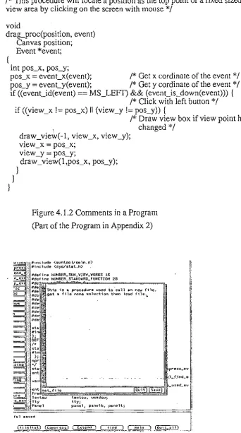
Parameters of the environment can be changed at any moment, at the start
point or in the middle of processing. Suppose a user calls an environment from
the system menu. All the parameters which can or cannot be changed are shown
in a box on the screen. For example, when an environment called "HI" is being
created, the box containing the parameters comes out where graph type is
unchangeable at this stage. Others may be accessed by scrolling in a cycle and
clicking on them.
hi
background (green), text font (12), graph type (tree),
The user can make changes at any place. Any action outside the box will
accept the parameters (they are default if there are no changes) and go into the
environment. This box is not only used for changing parameters but also used
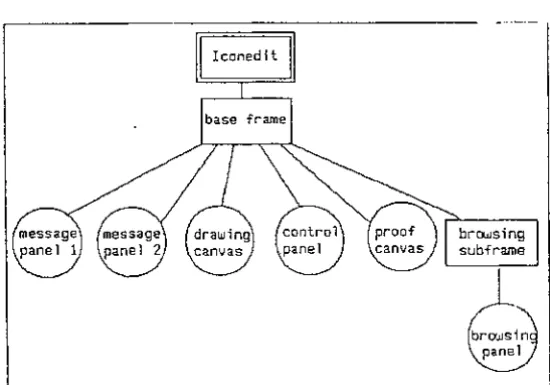
for showing the features of the environment, that is what a user can do in it. It