Precoder-Aided Iterative Detection Assisted Multilevel Coding and Three-Dimensional EXIT-Chart
Analysis
R. Y. S. Tee, S. X. Ng and
1L. Hanzo
School of ECS, University of Southampton, SO17 1BJ, UK.
Tel: +44-23-8059 3125, Fax: +44-23-8059 4508
Email:
1[email protected], http://www-mobile.ecs.soton.ac.uk
Abstract– A novel three-dimensional (3D) EXIT chart is developed for investigating the iterative behaviour of Mul-tilevel Coding (MLC) invoking Multistage Decoding (MSD). The extrinsic information transfer characteristics of both the symbol-to-bit demapper used and those of the different-protection constituent decoders suggest that potential im-provements can be achieved by appropriately designing the demapper. The proposed 3D EXIT chart is then invoked for studying the precoder-aided multilevel coding scheme employing both MSD and Parallel Independent Decoding (PID) for communicating over AWGN and uncorrelated Rayleigh fading channels with the aid of 8PSK modula-tion. At BER=10−5, the precoder was capable of enhancing the achievableEb/N0performance by 0.5dB to 2.5dB over AWGN and Rayleigh channels, respectively.
1. INTRODUCTION
Multilevel Coding (MLC) was introduced by Imai and Hirawaki [1] as a bandwidth efficient coded modulation scheme, which was designed for protecting each bit of non-binary modula-tion schemes with the aid of potentially different-rate binary codes. The so-called capacity rules have been proposed [2] for choosing appropriate coding rates that are capable of ap-proaching the channel capacity with the aid of Multistage De-coding (MSD), while Parallel Independent DeDe-coding (PID) has been employed as a design alternative for the sake of reducing the associated decoding delay. However, the iterative decoding behaviour of MLC schemes depends on the mutual information transfer characteristics of both the decoders as well as on those of the demapper used for conveying the demodulated bits to the constituent decoders.
With the objective of studying the iterative detection aided performance of MSD assisted MLCs, we propose a novel three-dimensional (3D) extrinsic information transfer (EXIT) [3] chart for investigating the effects of different symbol-to-bit demap-per characteristics. In the recent past, different constellation labeling strategies have been employed in the context of MLC for the sake of increasing either the Euclidean distance or the Hamming distance associated with the different modulation phasor points in order to achieve a better iterative detection
The financial support of the European Union under the auspices of the Phoenix and Newcom projects and that of the EPSRC, UK is gratefully ac-knowledged.
performance with the aid of optimized bit-to-symbol mappers / demappers [2] [4] [5]. In this paper, instead of optimizing the modem constellation labelling, we introduce a serially con-catenated unity-rate code [6] having a recursive structure as a precoder in the context of MLC schemes for the sake of en-hancing the demapper’s convergence characteristics. Further-more, we will benchmark our MLC MSD scheme against the Parallel Independent Decoding (PID) [2] scheme, which ex-hibits a significantly reduced decoding delay.
The rest of this contribution is organized as follows. Sec-tion 2 provides an overview of the system considered, while our novel 3D EXIT chart is invoked in Section 3 for the sake of characterizing the system’s iterative convergence behaviour. Section 4 quantifies the performance of our pre-coded MLC scheme, while our conclusions are presented in Section 5.
2. SYSTEM OVERVIEW
Demapper
Precoder
Channel inf.y
Lb2
Decoder 0,D0
Decoder 1,D1
Decoder 2,D2 L(v0)
L(v1)
L(v2) L(u1)
L(u2) L(u0) L0
e
L1 e
L2 e L
b2
L b0
L b1 Lb0
[image:1.595.311.552.390.548.2]Lb1
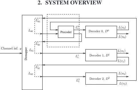
Figure 1: MSD Decoder of the 8PSK modulation based precoder-aided MLC scheme.
Figure 1 and 2 outline our MSD and PID schemes designed for operating in conjunction with 8PSK modulation, respec-tively. The notations L(ui) andL(vi) represent the output LLRs of the decoders for the original information bits and for the MLC-encoded bits, respectively. The subscriptirepresents the index of the different-protection bitsb0,b1andb2, while
Li
edenotes theextrinsicLLR generated at the output of the
innerdemapper. The rectangle drawn in dashed lines in both
Precoder
Precoder
Precoder
Demapper
Channel inf.y
Decoder 0,D0
Decoder 1,D1
Decoder 2,D2 L(v0)
L(u0) L0
e
L2 e L1 e
L(u1)
L(u2) L(v1)
[image:2.595.340.526.86.166.2]L(v2)
Figure 2: PID Decoder of the 8PSK modulation based precoder-aided MLC scheme.
the corresponding decoderDi, whileL
bidenotes thea priori LLRs forwarded by theotherdecoderDi to the input of the inner demapper.
00 00 00 11 11 11
00 00 11 11
00 00 11 11 00
00 00 11 11 11
0000000 0000000 0000000 0000000 0000000 0000000 0000000 0000000 0000000 0000000 0000000
1111111 1111111 1111111 1111111 1111111 1111111 1111111 1111111 1111111 1111111 1111111
0000000 0000000 0000000 0000000 0000000 0000000 0000000 0000000 0000000 0000000
1111111 1111111 1111111 1111111 1111111 1111111 1111111 1111111 1111111 1111111 0000000 1111111
00 00
01 01
0/1
1/1 input
+
output
D
(a) (b)
[image:2.595.308.564.243.374.2]0/1 1/1
Figure 3:Unity rate memory-1 precoder
To elaborate a little further, in the MSD decoder of Figure 1
thea prioriinformation is fed by the lower-protection decoder
to the higher-protection scheme. Each of the bitsb0,b1andb2 is decoded by the corresponding decoder, namely byD0,D1 andD2. The decoderDiprocesses both the received informa-tion bits ofLbias well as thea prioriinformation provided by
theotherdecoders and conveyed by the inner demapper seen
in Figure 1. By contrast, the PID structure shown in Figure 2 does not make use of the decisions carried out at other protec-tion levels. Instead, each decoder Di processes thea priori knowledge in a parallel and independent manner. Hence, this potentially results in a reduction of the associated processing delay.
Figure 3 portrays the unity-rate code employed in our pre-coder-aided MLC scheme, where D is a shift register stage and⊕represents the modulo-2 operation. Figure 3(b) shows the trellis diagram of the precoder. The trellis transitions are denoted byci/xi, wherecidenotes the input of the precoder at timei, whilexiindicates the corresponding precoder output.
In the system advocated, we employ convolutional codes as our component, where the individual coding rates of the MLC MSD and MLC PID schemes are 1/3, 3/4, 11/12 [7] and 1/2, 3/4 and 3/4 [2], respectively. Since the specific coding rates that are readily available for convolutional codes are con-strained, we do not follow the exact capacity rules proposed in [2] for adjusting the MLC scheme’s coding rate. The resultant effective throughput of the 8PSK system considered becomes
2 bits per symbol. All system parameters are summarized in Table 1.
Coding rate R0 R1 R2 MSD 1/3 3/4 11/12
PID 1/2 3/4 3/4
Precoders’ trellis states 00 and 01
Modulation 8PSK
Mapping type Set Partitioning (SP) Interleaver length 1800 symbols
Table 1:System parameters.
3. EXIT CHART BASED CONVERGENCE ANALYSIS
-+ Ψ
+
-Ψ
Li A
Li A(o)
Li A(comb)
Ψ−1
y Pe(Vi
t)
Li
E LoA
Ψ−1 yˆ
Lo E
Li A(o)
Li A(o)
Pa(Vi t)
Lb0 Lb1 Lb2 Lb0 Lb1 Lb2 Lb0 Lb1 Lb2
Ii E
Io E
Li
A LiA
MAP Decoder Demapper
a prioriLLR for level 0, 1 and 2
level0 level1 level2
Figure 4: EXIT chart generation for the MSD of 3-level MLC when using 8PSK and three en(de)coders.
In this section, we introduce a 3D EXIT chart for the sake of analyzing the iterative convergence behaviour of the MLC MSD scheme considered, where the demapper and decoder are referred to as theinnerandoutercodes. Figure 4 shows the schematic of generating the 3D EXIT chart. Specifically,La b represents the LLR values, where the superscript a denotes the inner (i) or outer (o) codes, while the subscript bdenotes the input a priori(A) or outputextrinsic(E) information. The variablesLb0,Lb1andLb2are independent Gaussian
dis-tributed LLRs generated for bits 0, 1 and 2, respectively. Fur-thermore,ΨandΨ−1 denote the LLR-to-symbol probability and symbol probability-to-LLR conversion. The arrow drawn in dashed line represents the extrinsic LLR demapper out-put, which becomes the LLR input of the decoder after demap-ping. The filled black box represents thea prioriLLR of the associated information bit, while the hollow box denotes the
a priori LLR of theotherdecoders’ bits. Both IEi andIEo,
which denote the mutual information accruing from theinner
andoutercodes are used for plotting the EXIT chart.
In order to generate the 3D EXIT chart for the MLC MSD scheme seen in Figure 1 for an 8PSK modulated system, we model the LLRsLiAandLiA(o)by independent Gaussian dis-tributed random variables [3] at MLC protection level 0, 1 and 2, as shown in Figure 4. Considering the example of protection
level0, the LLRLi
[image:2.595.48.295.281.367.2]gener-ated by theotherdecoders and indicated by the hollow boxes in Figure 4 are then computed along with their individual av-erage values for the sake of obtaining the combineda priori LLR ofLi
A(0). Similar operations are carried out at the decoder
of protectionlevel1andlevel2, each having the correspond-ing information bit represented by the black box at the appro-priate position. The mutual information corresponding toLi
A, Li
A(o)andLoAis represented byIAi,IAi(o)andIAo, respectively. In Figure 5, the EXIT plane marked with the mesh of tri-angles denotes the extrinsic information transfer characteris-tics of the inner demapper, while the plane represented by the mesh of rectangles characterizes theextrinsicinformation of the outer MAP decoder. The thick zig-zag shaped lines seen in Figure 5 represent the decoding trajectory evolving within the 3D tunnel, constituted by the inner demapper’s and the outer decoder’s EXIT planes. If the trajectory succeeds in converg-ing to the pointQ(1,1,1), the highest possible iteration gain is reached. We observe that the decoding trajectory of protection
level0 fails to reach this point owing to its deficient
demap-per characteristics. Hence, in order to improve the iterative decoding convergence of the overall MLC system, we have to improve the demapper characteristic at protectionlevel0. This can be achieved by introducing the precoders [6] shown in the dash-line boxes of Figure 1 and 2.
The beneficial effect of precoding on the attainable decod-ing convergence has been demonstrated by Narayanan in [8], where the recursive precoder ofg(D)=1⊕DRwas shown to attain a substantial gain. In the precoder’s generator polyno-mial, Rrepresents an integer which corresponds to the num-ber of shift register stages employed in the precoder structure. Here, we employ a low-complexity rate-1 precoder having the generator polynomialg(D)=1 +Dwithout adding further re-dundancy to the inner code’s demapper, which allows us to maintain the inner code’s original coding rate. Figure 3 demon-strates the implementational simplicity of the precoder, which has a 2-state trellis.
Precoder
-+
y
Li A(comb)
Pa(Vti)
Pe(Vti)
Lb2
Lb1
Lb0
level 0
Li A(o)
Demapper
Ψ−1
a prioriLLR for level 0
Ψ−1
-
ΨIi
E Li
E
+
Ii
A
Li A(data)
[image:3.595.47.285.482.640.2]Li A(info)
Figure 6:EXIT chart generation for the MSD MLC scheme of Figure 1, when using 8PSK and three en(de)coders.
The schematic of generating the 3D EXIT plane for
protec-tionlevel0of the precoder-aided MSD is shown in Figure 6.
The 3D EXIT plane of Figure 5 shows that the inner demapper
characteristics are only affected by the information bits pro-vided by the LLRs of the other LiA(o) decoders, regardless of its own intrinsic LLR Li
A. Hence in Figure 6, LiA(inf o) would only be regarded as dummy information and would not be exploited in the 3D EXIT chart for the sake of reducing its dimensions. In other words, theinnercode’s EXIT plane will not be affected by varying the values of Li
A(inf o). The LLRLi
A(data)is generated by theouterMAP decoder and in-put to the precoder. Therefore, the LLRsLi
A(o),LiA(data)and
Li
Ecorresponding to the mutual informationIAi(o),IAi andIEi are used for plotting the inner demapper’s EXIT characteris-tic. TheinnerEXIT characteristic plane is a function ofIi
E= f(Ii
A,IAi(o)).
Figure 7 portrays the 3D EXIT chart employing the pre-coder. The EXIT planes marked with the mesh of triangles and dashed lines characterize the precoded demapper at SNR=6dB and SNR=4dB, respectively, while the mesh of rectangles rep-resents the outer MAP decoder’s EXIT characteristics. Ob-serve in Figure 7 that there is no iteration gain at SNR=4dB, since the EXIT plane is trapped below the MAP decoder’s plane. By contrast, at SNR=6dB we are able to obtain an open tunnel between the two EXIT planes, which eventually reaches the point of decoding convergence atQ(1,1,1). Note that the trajectory evolves between the two planes and the a priori knowledge extracted from the associated information bits af-fects theextrinsicinformation as opposed to the MLC scheme characterized in Figure 5. More explicitly, with the aid of the precoder’sa priori information, the trajectory no longer evolves in parallel to they axis, as seen in Figures 5(a), 5(b) and 5(c), but instead it evolves in an angle as a function of bothIi
A(xaxis) andIAi(o)(yaxis), as shown in the dotted sec-tion of the trajectory seen in Figure 7. We now continue our discourse by introducing the precoder in the PID aided MLC scheme shown in Figure 2.
4. SIMULATION RESULTS
0.00 0.25
0.50 0.75 1.00
IA i
, IE o
(x) 0.00
0.25 0.50 0.75 1.00
IA(0) i
(y) 0.25
0.50 0.75 1.00 IE
i
, IA o
(z)
(a) Level 0
0.00 0.25
0.50 0.75 1.00
IA i
, IE o
(x) 0.00
0.25 0.50 0.75 1.00
IA(o) i
(y) 0.25
0.50 0.75 1.00 IE
i
,IA o
(z)
(b) Level 1
0.00 0.25
0.50 0.75 1.00
IA i
, IE o
(x) 0.00
0.25 0.50 0.75 1.00
IA(o) i
(y) 0.25
0.50 0.75 1.00 IE
i
, IA o
(z)
[image:4.595.57.546.67.211.2](c) Level 2
Figure 5:3D EXIT Chart for Level 0, Level 1 and Level 2 of the MLC scheme at SNR = 4dB.
0.00 0.25
0.50 0.75
1.00
IAi, IEo (x) 0.00
0.25 0.50 0.75 1.00
IA(0)i (y) 0.25
[image:4.595.51.288.239.433.2]0.50 0.75 1.00 IEi, IAo (z)
Figure 7:3D EXIT chart for protection level 0 of the precoder-aided MLC scheme of Figure 1 at SNR = 4dB (dotted dashed lines) and SNR = 6dB (mesh of triangles).
Figures 10 and 11 illustrate the attainable BER performance of the precoder-aided MLC PID scheme communicating over both AWGN and uncorrelated Rayleigh fading channels. At BER=10−5, the precoder-aided MLC scheme exhibits a sig-nificant coding advantage of about 2dB in AWGN channels and about 5dB in uncorrelated Rayleigh channels. Note that PID becomes capable of outperforming MSD in the precoder-aided MLC scheme, as the benefit of its higher iteration gain. This is due to the fact that the decision errors of the lower pro-tection levels may spread to the higher levels in MSD. Fur-thermore, SP-based mapping, which maximizes the Euclidean distance of phasor constellation points for the sake of obtain-ing an iteration gain, performs better in AWGN channels. In Figure 12, we further compare the precoder-aided MLC PID scheme to other coded modulation schemes having the same expressed complexity in terms of the number of trellis states
1 2 3 4 5 6 7 8 9 10
Eb/N0(dB)
10-6 10-5 10-4 10-3 10-2 10-1 1
BER
1 2 3 4 5 6 7 8 9 10
Eb/N0(dB)
10-6 10-5 10-4 10-3 10-2 10-1 1
BER
6 iterations 2 iterations 1 iteration
[image:4.595.312.555.250.413.2]using one memory-1 precoder using no precoder
Figure 8: BER versusEb/Noperformance of the conventional and precoder-aided 8PSK modulated MLC MSD scheme of Figure 1, communicating over an AWGN channel.
and communicating over uncorrelated Rayleigh fading chan-nels. Our precoder-aided MLC scheme exhibits a better BER performance associated with a coding advantage of 2.5dB at BER=10−5compared to the best-performing BICM-ID coded modulation scheme, although it is outperformed by TTCM, both of which were detailed in [9].
5. CONCLUSIONS
Alter-4 5 6 7 8 9 10 11 12 13 14 Eb/N0(dB)
10-5 10-4 10-3 10-2 10-1 1
BER
4 5 6 7 8 9 10 11 12 13 14
Eb/N0(dB)
10-5 10-4 10-3 10-2 10-1 1
BER
6 iterations 2 iterations 1 iteration
[image:5.595.311.554.60.229.2]with precoders with no precoder
Figure 9:BER versusEb/Noperformance of both conventional and precoder-aided 8PSK modulated MLC MSD scheme, communicating over uncorrelated Rayleigh channel.
1 2 3 4 5 6 7 8 9 10
Eb/N0(dB)
10-5 10-4 10-3 10-2 10-1 1
BER
1 2 3 4 5 6 7 8 9 10
Eb/N0(dB)
10-5 10-4 10-3 10-2 10-1 1
BER
6 iterations 2 iterations 1 iteration
[image:5.595.48.291.60.229.2]using 3 precoders using no precoder
Figure 10: BER versusEb/No performance of both conventional and precoder-aided 8PSK modulated MLC PID scheme, communi-cating over AWGN channel.
natively, at BER=10−5the precoder was capable of enhancing the achievableEb/N0performance by 0.5dB and 5dB, when
communicating over AWGN and Rayleigh channels, respec-tively. Our future research investigates the iterative decod-ing performance of combined MLCs and Generalized Low-Density Parity-Check (GLDPC) codes.
6. REFERENCES
[1] H. Imai and S. Hirawaki, “A New Multilevel Coding Method Using Error
Crrecting Codes,”IEEE Transactions on Information Theory, pp. 371–
377, May 1977.
[2] U. Wachsmann, R. F. H. Fischer and J. B. Huber, “Multilevel Codes:
The-oretical Concepts and Practical Design Rules,”IEEE Transaction on
In-formation Theory, vol. 45, pp. 1361–1391, July 1999.
[3] S. ten Brink, “Convergence Behavior of Iteratively Decoded Parallel
Con-catenated Codes,” IEEE Transactions On Communications, pp. 1727–
1737, October 2001.
4 5 6 7 8 9 10 11 12 13 14 Eb/N0(dB)
10-5 10-4 10-3 10-2 10-1 1
BER
4 5 6 7 8 9 10 11 12 13 14
Eb/N0(dB)
10-5 10-4 10-3 10-2 10-1 1
BER
6 iterations 2 iterations 1 iteration
[image:5.595.48.291.280.446.2]using 3 Precoders using no precoder
Figure 11: BER versusEb/No performance of both conventional and precoder-aided 8PSK modulated MLC PID schemes, communi-cating over uncorrelated Rayleigh channels.
6 7 8 9 10 11 12 13 14
Eb/N0(dB)
10-5 10-4 10-3 10-2 10-1 1
BER
Precoder-aided MLC PID, 32 states, 4-iter, SP mapping BICMID, 32 states, 4-iter
BICM, 128 states TTCM, 16 states, 4-iter TCM, 128 states
MLC MSD, 32 states, 4-iter, SP mapping
Figure 12: BER versusEb/Noperformance of various coded mod-ulation schemes having MAP decoding complexity associated with 128-trellis states, when communicating over uncorrelated Rayleigh channels using 8PSK modulation.
[4] D. F. Yuan, P. Zhang, Q. Wang and W. E. Stark, “A Novel Multilevel
Codes With 16QAM,”IEEE Wireless Communications and Networking
Conference, pp. 260–263, 2002.
[5] F. Schreckenbach and G. Bauch, “EXIT charts for iteratively decoded
multilevel modulation,” 12th European Signal Processing Conference
(EUSIPCO), 2004.
[6] D. Divsalar, S. Dolinar and F. Pollara, “Serial Concatenated Trellis Coded
Modulation with Rate-1 Inner Code,”IEEE Global Telecommunications
Conference, pp. 777–782, Nov. 2000.
[7] M. Isaka and H. Imai, “On the Iterative Decoding of Multilevel Codes,” IEEE Journal on Selected Areas in Comms, vol. 19, pp. 935–943, May 2001.
[8] K. R. Narayanan, “Effect of Precoding on the Convergence of Turbo
Equalization for Partial Response Channels,”IEEE Journal on Selected
Areas in Communications, pp. 686–698, Apr. 2001.
[9] L. Hanzo, T. H. Liew and B. L. Yeap,Turbo Coding, Turbo Equalisation
[image:5.595.311.553.281.449.2]