Research Article
Switchable Electromagnetic Bandgap Surface Wave Antenna
Qiang Bai, Kenneth L. Ford, and Richard J. Langley
Department of Electrical and Electronic Engineering, University of Sheffield, Mappin Street, Sheffield S1 3JD, UK Correspondence should be addressed to Richard J. Langley; [email protected]
Received 3 December 2013; Accepted 20 February 2014; Published 10 April 2014
Academic Editor: Giacomo Oliveri
Copyright © 2014 Qiang Bai et al. This is an open access article distributed under the Creative Commons Attribution License, which permits unrestricted use, distribution, and reproduction in any medium, provided the original work is properly cited.
This paper presents a novel switchable electromagnetic bandgap surface wave antenna that can support both a surface wave and normal mode radiation for communications at 2.45 GHz. In the surface wave mode, the antenna has a monopole-like radiation pattern with a measured gain of 4.4 dBi at±49∘and a null on boresight. In the normal mode, the antenna operates like a back-fed microstrip patch antenna.
1. Introduction
Many types of wearable antennas have been proposed in recent years designed for body area networks (BANs). Anten-nas may operate in either of two modes, on-body and off-body. On-body communication refers to the transmission of signals across the human body as a surface wave, which requires the wearable antenna to have maximum directivity along the body surface while, in the off-body (normal) mode, the communication occurs away from body to a node such as a base station, which demands that the antenna have the maximum radiation in the boresight direction. Therefore ideally such antennas have to be designed to support each mode of operation. For many antennas, it is useful if they are able to operate without being affected by their environment, for example, radiating into the human body or placing them on metal surfaces such as vehicles. Hence, a large ground plane or electromagnetic bandgap (EBG) structure may be also necessary to reduce the detuning effect and the backward radiation. Some antenna designs using EBGs as artificial magnetic conductors (AMCs) have been reported in [1–
5] for off-body communication and in [6–8] for on-body communication. Only a small number of papers have studied a switchable system which can support both on- and off-body communications [9–11].
The mushroom-like EBG structure has been well studied and widely used in various designs to improve antenna performance [1, 12,13]. Recent research also observed that the surface wave bandgap may disappear when the vertical
vias are removed from the mushroom-like EBG structure. Hence instead of being suppressed, a strong surface wave can be exited and radiated on the via-less EBG material. Based on this feature, several surface wave antennas (SWA) have been designed to achieve a monopole-like radiation pattern on a thin, planar structure [14, 15]. However, in previous designs, the antenna could only support surface wave communication, and it was difficult to achieve the normal mode communication feature as the antenna was fully covered by the EBG cells.
This paper presents a novel switchable surface wave antenna based on bandgap materials which keeps the planar structure and low thickness but can support both surface wave (on-body) and normal (off-body) modes of com-munication at 2.45 GHz. Although not designed on textile materials, this paper shows the techniques for generating a dual mode switchable antenna. The performance of the antennas is investigated based on numerical and experi-mental methods. CST Microwave Studio was used for the antenna simulations. The surface wave communication mode is further investigated by studying the use of an EBG to couple antennas/sensors together around the body.
2. Antenna Design
190mm
100
mm
(a)
PIN diode Parasitic patch 4 25mm EBG
EBG
FR4 Feed
FR4
z
[image:2.600.79.520.72.194.2]y (b)
Figure 1: Geometries of the switchable SWA: (a) top view, EBG based antenna layer with PIN diode switches, (b) side view.
(a)
180
135 90 45 0 −45 −90 −135 −180
Reflec
tio
n p
has
e (deg)
0 1 2 3 4 5
Frequency (GHz)
(b)
(c) (d)
Figure 2: (a) Photograph of the fabricated model (without PIN diodes), (b) EBG reflection phase, (c) simulated radiation patterns for antenna with EBG, (d) simulated radiation patterns for antenna without EBG.
from the patch centre. The top layer consists of a parasitic identical patch aligned above the lower patch antenna and an optimized EBG surface (Figure 1(a)). The EBG, with 25 mm× 25 mm unit cell, was designed, so that a surface wave was excited and propagated when the reflection phase of the EBG cell was approximately −90∘ (Figures 2(a) and 2(b)) [15]. There are six strips at the edges of the surface and six PIN diodes switching the EBG surface to the strips to give the radiation characteristics. Both layers are made of FR4 material with a total thickness of 3.2 mm and an overall size of
100×190 mm. The bias network can be printed on the back side of the top layer to actuate the PIN diodes. And also the PIN diodes can be replaced by varactor diodes to tune the surface response.
[image:2.600.95.507.236.572.2]60
90
120
150 180
210 240
270
300 −15
−25
−35 −25 −15
Without EBG
With EBG,t = 3
With EBG,t = 4
[image:3.600.314.543.72.268.2]With EBG,t = 5
Figure 3: Simulated radiation patterns of switchable surface wave antenna (whent= 3, 4, 5 mm and without EBG).
3. Simulation and Measurement
3.1. Simulation. Initially, the EBG layer, with parasitic patch
inclusion, was spaced a distance, t, from the fed patch.
Figure 3plots the simulatedy-z plane radiation patterns of the patch antenna alone and the patch antenna with the EBG surface for varying distances,t. For easy comparison, all radiation patterns in this paper are normalized. From
Figure 3, the peak power from the radiation pattern varies from boresight for the patch antenna to approximately 50∘ with the EBG when the separation, t, is set to 4 mm and a null appears at boresight. There is an appreciable amount of radiation directed sideways from the antenna, along the EBG. It is also found inFigure 4that the antenna matching performance was not significantly affected, maintaining the resonance at about 2.4 GHz.
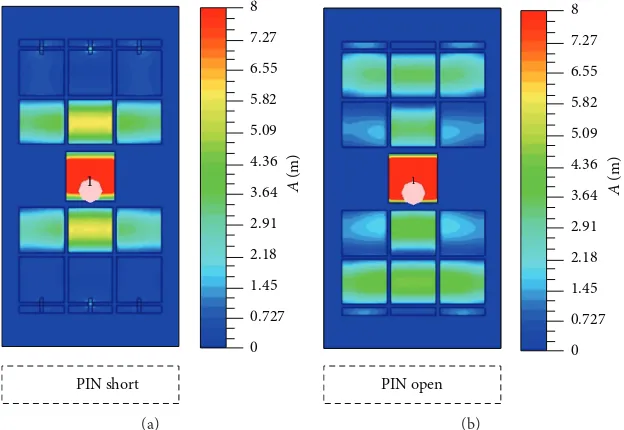
The operation of the EBG antenna is clearly shown by the current distributions on the surface in the two modes (Figure 5). For the PIN diodes shorted in Figure 5(a), the currents are confined to the parasitic patch and the six elements of the EBG closest to it which form the antenna radiating away from the patch. With the PIN diodes open circuit, the whole of the EBG is excited directing the radiation along the antenna surface.
3.2. Measurement. Figure 6presents the measured reflection
coefficient of the switchable surface wave antenna to be compared with the simulation inFigure 4. In both modes (pin open and short circuit), the antenna has−10 dB bandwidth covering 2.4 GHz to 2.47 GHz. The antenna working band is shifted upwards by 20 MHz, covering the band from 2.42 GHz to 2.49 GHz in the measurements. This may be
−10
−15
−20
−25
−30
1.8 2 2.2 2.4 2.6 2.8 3
S
-pa
ra
m
et
er
s (dB)
Frequency (GHz)
S11
Without EBG
With EBG,t = 2
With EBG,t = 3
[image:3.600.61.279.74.318.2]With EBG,t = 4
Figure 4:S11of switchable surface wave antenna (whent= 2, 3, 4 mm and without EBG).
caused by the inaccuracy of the manufacture as a thin air gap is noticed when the antenna top layer and lower layer are assembled together. Unlike in previous EBG surface wave antennas reported in [14,15], where the resonant frequency highly depends on the EBG, the matching performance of proposed antenna in this paper is only slightly affected when the top EBG structure is switched, giving an opportunity to tailor the antenna radiation pattern without changing the resonant frequency.
The measuredy-zplane radiation patterns for the switch-able surface wave antenna are plotted in Figure 7. In the surface wave mode, the antenna has the maximum directivity at ±49∘ with a measured gain of 4.4 dBi and a null is also obtained in the boresight direction. When switched to the normal mode, the antenna mainly radiates towards the boresight direction (red dotted line in the figure) with a gain of 3.7 dBi. It is also noted, due to the large ground plane, that the antenna has low backward radiation in both modes. Overall, the simulated and measured performance of the antenna are in good agreement.
4. EBG Waveguide
8 7.27 6.55 5.82 5.09 4.36 3.64 2.91 2.18 1.45 0.727 0 1
PIN short
A
(m)
(a)
1
PIN open
8 7.27 6.55 5.82 5.09 4.36 3.64 2.91 2.18 1.45 0.727 0
A
(m)
[image:4.600.143.455.74.289.2](b)
Figure 5: Surface currents on EBG antenna. (a) PIN diodes shorted. (b) PIN diodes open.
0 −5 −10 −15 −20 −25 −30 −35 −40
1.8 2 2.2 2.4 2.6 2.8 3
Frequency (GHz)
S
-pa
ra
m
et
er
s (dB)
[image:4.600.318.539.336.582.2]PIN open PIN short
Figure 6: MeasuredS11of switchable surface wave antenna.
in the surface wave mode. The antennas remain switchable and are separated from centre to centre by 315 mm. The bandgap surface is shown as 3 elements wide by 6 elements long but this is for demonstration only and can be extended lengthwise as required. Three unit cell elements in width are sufficient for the EBG to operate satisfactorily rather than 2 elements. Five-element width was also tested, but there was no significant improvement obtained on transmission performance.
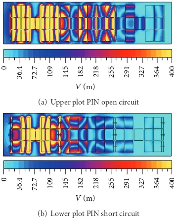
Figure 9shows the surface currents for the cases with the PIN diodes both open and short circuit and it is clear that the EBG propagates a wave from one antenna to the other when the diodes are open circuit. The transmission coefficients,
S21, for both cases are plotted inFigure 10where simulations and measurements are compared. When the PIN diodes are
PIN short PIN open
0
30
60
90
120
150 180
210 240
270 300
330 −5
−15
−25
−35 −25 −15 −5
Figure 7: Measured radiation patterns of switchable surface wave antenna iny-zplane for pin diodes open and short circuit.
[image:4.600.57.286.336.521.2]315mm
[image:4.600.315.543.653.724.2]40
0
364
32
7
29
1
25
5
218
182
14
5
109
72.7
36.
4
0
V(m)
(a) Upper plot PIN open circuit
40
0
364
32
7
29
1
25
5
218
182
14
5
109
72.7
36.
4
0
V(m)
[image:5.600.348.511.71.262.2](b) Lower plot PIN short circuit
Figure 9: Surface currents on EBG coupled antenna system.
0
−10 −20 −30 −40 −50 −60 −70 −80
T
ra
n
smissio
n co
efficien
t (dB)
1.8 2 2.2 2.4 2.6 2.8 3
Measured PIN open cct Measured PIN short cct
Simulated PIN open cct Simulated PIN short cct Frequency (GHz)
Figure 10: Measured and simulated transmission coefficients (S21) between switchable mode antennas.
[image:5.600.81.257.72.293.2]open circuit, the measured transmission was−21 dB between the antennas while the calculated value was about−23 dB. When the PIN diodes were short circuited, the transmission between the antenna and the EBG is considerably reduced (seeFigure 5(a)) and hence the EBG carries little signals to the other antenna and the measured transmission falls to−33 dB for the measurement and−41 dB in the simulation. Manu-facturing difficulties probably account for the discrepancy between the measured and calculated results as there was a small uneven air gap between the layers of the structure. In addition, for the simulation, the PIN diodes are assumed to be perfect switches.
Figure 11shows the simulated 3D radiation pattern from the whole structure when operating in the normal mode showing that the full structure with the EBG was able to
Figure 11: Radiation pattern for complete antenna/EBG with PIN diodes short circuit, normal mode.
switch between the normal mode (radiation away from antenna) and the surface wave mode with the EBG acting as a transmission medium as inFigure 9.
To further demonstrate propagation across the antennas with and without the connecting EBG, the antenna system is bent around a tissue equivalent phantom [6] with a diameter of 100 mm as shown in Figures12(a)and12(b)respectively. InFigure 12(c)the surface currents excited on the antenna structure are shown in both cases. From Figure 12(c), it is clear that the EBG propagates the wave around the bend to the second antenna.
The simulated transmission coefficients (S21) are plotted inFigure 13for the bent geometry and compared with the value when the surface was flat. The coupling for the curved surface with the EBG increases from−45 dB without the EBG to −23 dB, although it does not reach the value of −18 dB for the flat surface with EBG. Typical S21 between antennas located at top and bottom of this tissue equivalent phantom is below−40 dB [6].
5. Conclusion
[image:5.600.53.285.332.516.2]D = 100mm
(a) Antennas without EBG connection (b) Antennas with EBG
400
364 327 291 255 218 182 145 109 72.7 36.4 0
V
(m)
400
364 327 291 255 218 182 145 109 72.7 36.4 0
V
(m)
[image:6.600.75.533.77.355.2](c) Simulated surface currents
Figure 12: Antennas bent on a radius of 100 mm.
0
−10 −20 −30 −40 −50 −60 −70 −80
T
ra
n
smissio
n co
efficien
t (dB)
Frequency (GHz)
1.8 2 2.2 2.4 2.6 2.8 3
Flat with EBG (Figure 8) Bent with EBG (Figure 12(b)) Bent without EBG (Figure 12(a))
S21
Figure 13: Transmission coefficientsS21for bent antenna surface.
Conflict of Interests
The authors declare that there is no conflict of interests regarding the publication of this paper.
Acknowledgment
This work is funded by the UK Engineering and Physical Sciences Research Council (EPSRC) Grant Reference no. EP/G056633.
References
[1] S. Zhu and R. Langley, “Dual-band wearable textile antenna on an EBG substrate,” IEEE Transactions on Antennas and Propagation, vol. 57, no. 4, pp. 926–935, 2009.
[2] P. Salonen, K. Jaehoon, and Y. Rahmat-Samii, “Dual-band E-shaped patch wearable textile antenna,” inProceedings of the IEEE Antennas and Propagation Society International Sympo-sium and USNC/URSI Meeting, pp. 466–469, July 2005. [3] M. Klemm, I. Locher, and G. Tr¨oster, “A novel circularly
polar-ized textile antenna for wearable applications,” inProceedings of the 34th European Microwave Conference, pp. 137–140, October 2004.
[4] A. R. Chandran and W. G. Scanlon, “Dual-band low profile antennas for body-centric communications,” inProceedings of the International Workshop on Antenna Technology (iWAT ’10), pp. 1–4, March 2010.
[image:6.600.57.285.433.640.2]on-body communication systems,” inProceedings of the IEEE International Workshop on Antenna Technology (IWAT ’05), pp. 17–20, March 2005.
[8] L. Akhoondzadeh-Asl, P. S. Hall, and Y. Nechayev, “Novel con-formal surface wave Yagi antenna for on-body communication channel,” inProceedings of the IEEE International Symposium on Antennas and Propagation (AP-S/URSI ’10), pp. 1–4, July 2010. [9] A. R. Chandran, G. A. Conway, and W. G. Scanlon, “Pattern
switching compact patch antenna for on-body and off-body communications at 2.45 Ghz,” inProceedings of the 3rd European Conference on Antennas and Propagation (EuCAP ’09), pp. 2055–2057, March 2009.
[10] J. Kelly, L. Ford, and R. Langley, “Slotline structure for on/off-body communications at 2.45 GHz,” inProceedings of the 5th European Conference on Antennas and Propagation (EUCAP ’11), pp. 525–529, April 2011.
[11] R. J. Langley, K. L. Ford, and Hyung-Joo Lee, “Switchable on/off-body communication at 2.45 GHz using textile microstrip patch antenna on stripline,” inEuropean Conference on Antennas and Propagation (EuCAP ’12), pp. 728–731, 2012.
[12] P. Salonen and Y. Rahmat-Samii, “Textile antennas: effects of antenna bending on input matching and impedance band-width,”IEEE Aerospace and Electronic Systems Magazine, vol. 22, no. 12, pp. 18–22, 2007.
[13] D. Sievenpiper, L. Zhang, R. F. Jimenez Broas, N. G. Alex¨opolous, and E. Yablonovitch, “High-impedance electromagnetic surfaces with a forbidden frequency band,” IEEE Transactions on Microwave Theory and Techniques, vol. 47, no. 11, pp. 2059–2074, 1999.
[14] F. Yang, A. Aminian, and Y. Rahmat-Samii, “A novel surface-wave antenna design using a thin periodically loaded ground plane,”Microwave and Optical Technology Letters, vol. 47, no. 3, pp. 240–245, 2005.
International Journal of
Aerospace
Engineering
Hindawi Publishing Corporation
http://www.hindawi.com Volume 2014
Robotics
Journal ofHindawi Publishing Corporation
http://www.hindawi.com Volume 2014
Hindawi Publishing Corporation
http://www.hindawi.com Volume 2014 Active and Passive Electronic Components
Control Science and Engineering Journal of
Hindawi Publishing Corporation
http://www.hindawi.com Volume 2014
Hindawi Publishing Corporation
http://www.hindawi.com Volume 2014
Hindawi Publishing Corporation http://www.hindawi.com
Journal of
Engineering
Volume 2014Submit your manuscripts at
http://www.hindawi.com
VLSI Design
Hindawi Publishing Corporation
http://www.hindawi.com Volume 2014
Hindawi Publishing Corporation
http://www.hindawi.com Volume 2014
Shock and Vibration
Hindawi Publishing Corporation
http://www.hindawi.com Volume 2014
Civil Engineering
Advances inAcoustics and VibrationAdvances in
Hindawi Publishing Corporation
http://www.hindawi.com Volume 2014
Hindawi Publishing Corporation
http://www.hindawi.com Volume 2014
Electrical and Computer Engineering
Journal of
Advances in OptoElectronics
Hindawi Publishing Corporation
http://www.hindawi.com Volume 2014
The Scientific
World Journal
Hindawi Publishing Corporationhttp://www.hindawi.com Volume 2014
Sensors
Journal of Hindawi Publishing Corporationhttp://www.hindawi.com Volume 2014
Modelling & Simulation in Engineering Hindawi Publishing Corporation
http://www.hindawi.com Volume 2014
Hindawi Publishing Corporation
http://www.hindawi.com Volume 2014 Chemical Engineering
International Journal of Antennas and
Propagation
International Journal of
Hindawi Publishing Corporation
http://www.hindawi.com Volume 2014
Hindawi Publishing Corporation
http://www.hindawi.com Volume 2014
Navigation and Observation
International Journal of
Hindawi Publishing Corporation
http://www.hindawi.com Volume 2014