6th International Conference on Nanomanufacturing, nanoMan2018, 04-06 July 2018, Brunel
University London, UK
Design and Integration of a High-precision Material Handling
System with a Six-axis Hybrid Micro-machine
Ross Walker
a, Wenbin Zhong
b, Xianwen Kong
a*, Xichun Luo
b*1
aDepartment of Mechanical Engineering, School of Engineering and Physical Sciences, Heriot-Watt University, Edinburgh, EH14 4AS, UK bCentre for Precision Manufacturing, DMEM, University of Strathclyde, Glasgow, G1 1XJ, UK
Abstract
Hybrid micro-machines are increasingly in demand for the manufacturing of miniature 3D products made of hard-to-machine materials. A high-precision material handling system for such miniature products can increase the overall efficiency significantly. This paper proposes the design of a machine vision based handling system, which is capable of handling various miniature 3D products. A cloud-based innovative integration method is also developed, a cloud server is deployed to collect and process data from the machine and the material handling system, their actions are coordinated based on the predefined protocol. This method can enhance the reconfigurability of the whole system.
Keywords: Material handling; Hybrid micro-machine; Machine vision; Cloud technology; System integration
1.Introduction
Hybrid machining, which combines conventional and non-conventional machining techniques on one machine bed, has been proved to be a cost-effective and efficient way of machining miniature 3D products with hard-to-machine materials, such as molds/dies and biomedical implants etc., while achieving satisfactory surface finish. The dimensions of these products range from hundreds of micrometers to a few millimeters. A high-precision material handling system is often required to efficiently load and unload these products in the automatic manner. Both the hybrid micro-machine and the material handling system tend to incorporate proprietary components from multiple vendors to fulfil the requirements of the machining and handling of these products, the interoperability and scalability between the two systems are usually at the second priority. This inevitably leads to complex and inflexible whole system. However, the rapid development of cloud technology provides novel solution to the system control.
The design of the six-axis hybrid micro-machine has been presented in [1], as shown in Fig. 1. It successfully combines laser and laser-assisted machining with micro-milling and micro-grinding. The design and integration of the material handling system will be presented in this paper.
Fig. 1. The six-axis hybrid micro-machine.
2.Illustrations
The material handling system is required to manipulate a wide range of parts from lenses and cases in the millimetre range, to the 55×55×41mm machining centre chuck. This offers the first challenge in developing the system, as when loaded with raw material the chuck can have a mass of up to 1.2kg. However, the lenses and case must be manipulated with as little gripping force as possible. This creates a challenge in determining an appropriate gripper as a wide stroke and gripping force range is required. Additionally, this creates challenges for the vision system, as a wide field of view is required to detect the parts which will not be picked from a defined position. However, accuracy will be critical when determining the position of the small components and the placement accuracy must be 0.1mm or greater.
Furthermore, the system must tighten/loosen the screws on the Erowa chuck to a torque of 5 Nm, to secure raw material. Finally, the loaded chuck must be placed 340mm inside the machining centre.
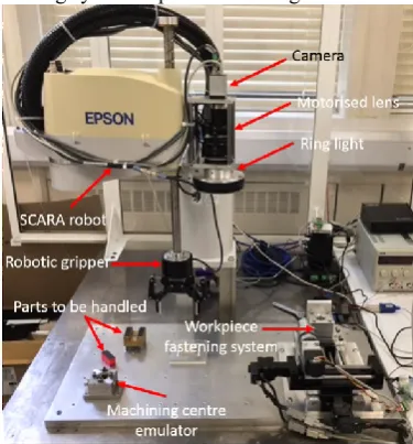
[image:2.595.204.392.248.450.2]The complete and assembled handing system is presented in Fig. 2.
Fig. 2. Assembled and function material handling system.
2.1. Epson SCARA Robot
It is clear from the system requirements that a 4-DOF system will be required. A SCARA robot would be an appropriate choice as it can translate along three axes rotate about the Z-axis and has a cylindrical work envelope. Additionally, the selective compliance attribute of the SCARA robot is beneficial when overcoming the “peg-and-hole problem,” as described in [2], [3]. This problem is comparable to the problem faced when placing the chuck into the workpiece holder and chuck fastening system, as will be presented in section 2.4.
The Epson SCARA ES653S, with an Epson SRC-320 controller, was determined to be an excellent choice of manipulator as it has a repeatability of 30µm; a maximum reach of 650mm and payload of 5kg. Hence, it meets the system requirements.
2.2. Robotiq Two Finger 85 Gripper
The Robotiq two-finger 85 gripper [4] was determined as an appropriate choice for end-effector. The maximum gripping force required to manipulate the load of 1.2kg is 32.4N, assuming a low coefficient of friction of 0.2 and safety factor of 10%. Additionally, the casings are rated to an applied force of 20N. This gripper has a suitable gripping force range from 5-50N. In addition, a jaw pitch of greater than 55mm is required and this gripper provides a pitch of 85mm, with 8-bit resolution. Therefore, the displacement resolution is 333µm. This gripper has two modes of operation, parallel and encompassing grip, which allows for manipulation of circular geometries.
To fulfil the requirement of the system to automate the fastening and loosening of raw material/parts in the machining centre chuck, a subsystem has been developed to individually tighten its four screws. The assembled system consists of two stacked Newmark system eTrack linear stages to form an XY cartesian stage, with an accuracy of 60µm and a travel range of 100mm. Mounted on the XY stage is a stepper motor and 25:1 reduction gearbox which provides actuation and a torque of up to 5.8Nm to a hex bar, which is used to fasten the screws on the workpiece holder. Encoders connected to the stepper motors provide feedback. Hence, PID compensation has been realised using the Newmark Systems NSC-A2L controller and Nanotech SMCI33-1 controller for the XY stage and drive motor, respectively.
As was mentioned in section 2.1, the placement of the chuck into this sub-system is like the “peg and hole problem” and the placement accuracy must be 0.5mm or greater. However, chamfering around the placement allows for the effective use of the SCARA’s selective compliance attribute and correction for inaccurate placement.
2.4. Development of Vision System
Vision systems have been incorporated into SCARA robots frequently in literature, for instance in visual servoing (as developed by [5]–[7]) and part detection (as developed by [8], [9]).
As can be seen from Fig. 2, the vision system has been mounted above the end-effector and will be used for accurate part recognition and detection. The developed vision system consists of a Baumer 2.8Mp 1/1.2” CMOS mono camera; motorised zoom and focus Navitar 7000 lens (18-108mm focal length) and red (λ=625nm) ring light. This system will allow for the imaging of parts as small as 54µm (using 2 pixels for detection, with 108mm focal length) and field of views as large as 270×169mm, with 18mm focal length.
The vision system was calibrated by imaging a Thorlabs calibration standard, which consists of concentric squares from 0.1×0.1mm to 50×50mm. The zoom and focus functions of the vision system were calibrated by maintaining the zoom at 18mm and changing focus; and then by focusing on the calibration standard and changing the zoom. This was then repeated for different working distances. Equations were then determined for each calibration set using curve fitting techniques and ensuring that the Person Product-Moment correlation coefficient (R2) was 0.99 for all datasets.
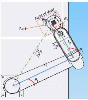
The parts were not placed on a controlled and noiseless background. Hence, a background subtraction method was used to remove artefacts. Following this edge detection is used to determine the center of the part in the camera coordinate frame. A schematic diagram used to determine the position of the part relative to the base coordinate system is presented in Fig. 3. Hence, the following equations are used to determine the centre of the camera relative to the base coordinate system:
𝑃𝐶𝑥 = 𝑙1𝑐𝑜𝑠 𝜃1+ 𝑙2𝑐𝑜𝑠(𝜃1+ 𝜃2) + 𝑙3𝑐𝑜𝑠(𝜃1+ 𝜃2+ 𝜃2) (1)
𝑃𝐶𝑦 = 𝑙1𝑠𝑖𝑛 𝜃1+ 𝑙2𝑠𝑖 𝑛(𝜃1+ 𝜃2) + 𝑙3𝑠𝑖𝑛(𝜃1+ 𝜃2+ 𝜃3) (2)
Following detection of the part in the image coordinate frame(𝑃𝑖), the following equations are used to
determine the center of the part in the SCARA’s base coordinate frame (𝑃𝑝).
𝑃𝑝𝑥= 𝑝𝑖𝑥(𝑝𝑖𝑥𝑒𝑙𝑠) 𝑐𝑜𝑠(𝜃𝐶𝑎𝑙𝑖𝑏𝑟𝑎𝑡𝑖𝑜𝑛1+𝜃2+𝜃2)+ 𝑝𝑖𝑥(𝑝𝑖𝑥𝑒𝑙𝑠)𝑠𝑖𝑛(𝜃𝐶𝑎𝑙𝑖𝑏𝑟𝑎𝑡𝑖𝑜𝑛1+𝜃2+𝜃2)− 𝑃𝐶𝑥 (3)
𝑃𝑝𝑦= 𝑃𝐶𝑦−
𝑝𝑖𝑦(𝑝𝑖𝑥𝑒𝑙𝑠) 𝑠𝑖𝑛(𝜃1+𝜃2+𝜃2)
𝐶𝑎𝑙𝑖𝑏𝑟𝑎𝑡𝑖𝑜𝑛 +
𝑝𝑖𝑦(𝑝𝑖𝑥𝑒𝑙𝑠)𝑐𝑜𝑠(𝜃1+𝜃2+𝜃2)
𝐶𝑎𝑙𝑖𝑏𝑟𝑎𝑡𝑖𝑜𝑛 (4)
Hence, the joint angles 𝜃1∗ and 𝜃2∗ are determined such that the SCARA can be moved to position the part in
the centre of the image frame. Following this, a second image is taken at increased focal length to improve the resolution of the part detection.
𝜃1∗= 𝑎𝑡𝑎𝑛 ( 𝑃𝑝𝑦
𝑃𝑝𝑥) − 𝑎𝑐𝑜𝑠 ( 𝐽𝑏𝑃𝑝
⃑⃑⃑⃑⃑⃑⃑⃑⃑⃑ 2+𝑙12 −𝐽⃑⃑⃑⃑⃑⃑⃑⃑⃑⃑ 1𝑃𝑝2
2𝑙1𝐽⃑⃑⃑⃑⃑⃑⃑⃑⃑⃑ 𝑏𝑃𝑝 ) (5)
𝜃2∗= 𝜋 − [𝑎𝑐𝑜𝑠 ( 𝐽1𝑃𝑝
⃑⃑⃑⃑⃑⃑⃑⃑⃑⃑ 2+𝑙22 −𝑙32
2𝑙2𝐽⃑⃑⃑⃑⃑⃑⃑⃑⃑⃑ 1𝑃𝑝 ) + 𝑎𝑐𝑜𝑠 ( 𝐽1𝑃𝑝
⃑⃑⃑⃑⃑⃑⃑⃑⃑⃑ 2+𝑙12 −𝐽⃑⃑⃑⃑⃑⃑⃑⃑⃑⃑ 𝑏𝑃𝑝2
2𝑙1𝐽⃑⃑⃑⃑⃑⃑⃑⃑⃑⃑ 1𝑃𝑝 )] (6)
Finally, the following equations are used to determine the position (𝑃𝑔) of the part for picking by the gripper.
𝑃𝑔𝑥= 𝑙1𝑐𝑜𝑠 𝜃1+ 𝑙2𝑐𝑜 𝑠(𝜃1+ 𝜃2) (7)
𝑃𝑔𝑦 = 𝑙1𝑠𝑖𝑛 𝜃1+ 𝑙2𝑠𝑖 𝑛(𝜃1+ 𝜃2) (8)
Fig. 3. Schematics diagram of the SCARA robot and vision system, showing links and relevant joint angels.
2.5. Measurement of Pose Accuracy
Using the process for detecting a part using the vision system, the pose accuracy was determined in accordance with ISO 9283:1998. To do this the Erowa chuck was imaged at five points within the workspace. The process used to determine the position of the part was described in Figure 3. The aim of this process is to position the SCARA such that the part is centered in the image frame. Hence, the positioning error is defined from the offset of the part to the center of the frame. The process was repeated 35 times for each point. Fig. 4 (a) presents a schematic representation of how the parts were positioned, while (b) presents a scatter plot of the positioning offset in the XY plane.
It is clear from this plot that the points are positioned in tight clearly defined clusters. Hence, the repeatability of the system is observably high. Clearly, the points are not positioned around the center. This is a result of the nonlinearity and non-common in SCARA robots. It is unsurprising the points measured at the center have the lowest offset as the value of 𝑙3 (equations (1) and (2)) was calibrated to reduce the error when at this pose.
Fig. 4. (a) schematic representation of how the part positions, (b) a scatter plot of the positioning offset in the XY plane.
Hence, it has been calculated that the system has a positioning accuracy of 0.125mm. Clearly this is 25µm larger than the required specification. Hence, further work will be required to reduce this error. The compensation control methods described in this section may be investigated to achieve this.
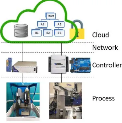
3.Cloud Based Integration
The hybrid micro-machine uses specialized CNC controller, while the material handling system consists of several controllers to control the gripper, robot and process images. Extensive data exchange between the two systems is required to coordinate the machining and handling of the products. A typical communication cycle includes command/data from one side and acknowledgement from the other side.
To avoid the high-degree interconnection between the two hardware platforms and simplify the reconfiguration of the hardware platforms, a cloud server is developed to integrate the networked machine and material handling system, as shown in Fig. 5. The cloud server collects data from hardware platforms and
[image:4.595.135.468.434.567.2]process it for coordinating and diagnosing. It also provides possibility to modify current process or integrate another process without affecting other processes. Remote access to the processes is also made possible.
[image:5.595.196.404.150.361.2]Network latency is an important issue for the cloud-based integration. In this application, Microsoft Azure is selected as the cloud platform. The average latency from the laboratory in the University of Strathclyde to the Microsoft Azure datacenter in the UK South (London) is below 50 ms [10], which satisfies the timing requirement for the communication.
Fig. 5. The cloud-based integration.
4. Conclusion
A high-precision material handling system is designed to handle various miniature 3D products. It uses machine vision to determine the position of the products, the pick and place accuracy is better than 150 µm. The cloud-based integration of the material handling system is also proposed, it eliminates the high-degree interconnections between different hardware platforms, which improves the reconfigurability of the whole system.
Acknowledgements
The authors would like to thank the support from Engineering and Physical Sciences Research Council (EPSRC) under the program EP/K018345/1.
References
[1] W. Chang, W. Zhong, F. Ding, F. Wardie, and X. Luo, “Development of a compact ultra-precision six-axis hybrid micro-machine,” in 2017 World Congress on Micro and Nano Manufacturing, 2017.
[2] H. Makino, “Development of the SCARA,” J. Robot. Mechatronics, vol. 26, no. 1, pp. 5–8, 2014.
[3] W.-B. Li, G.-Z. Cao, X.-Q. Guo, and S.-D. Huang, “Development of a 4-DOF SCARA robot with 3R1P for pick-and-place tasks,” in Power Electronics Systems and Applications (PESA), 2015 6th International Conference on, 2015, pp. 1–5.
[4] Robotiq, “Robotiq two finger 85 and 140 data sheet.” [Online]. Available: www.Robotiq.com. [Accessed: 20-Jul-2017].
[5] W.-C. Chang, M.-Y. Cheng, and H.-J. Tsai, “Image feature command generation of contour following tasks for SCARA robots employing Image-Based Visual Servoing—A PH-spline approach,” Robot. Comput. Integr. Manuf., vol. 44, pp. 57–66, 2017.
[6] C.-Y. Hu, C.-R. Chen, C.-H. Tseng, A. P. Yudha, and C.-H. Kuo, “Visual servoing spanner picking and placement with a SCARA manipulator,” in Industrial Technology (ICIT), 2016 IEEE International Conference on, 2016, pp. 1632–1637.
[7] H.-S. Sim, Y. Koo, S.-H. Jeong, D.-K. Ahn, B.-N. Cha, and S.-H. Han, “A study on visual feedback control of SCARA robot arm,” in Control, Automation and Systems (ICCAS), 2015 15th International Conference on, 2015, pp. 1268–1270.
[8] C. Martinez, R. Boca, B. Zhang, H. Chen, and S. Nidamarthi, “Automated bin picking system for randomly located industrial parts,” in Technologies for Practical Robot Applications (TePRA), 2015 IEEE International Conference on, 2015, pp. 1–6.
[9] B. B. Biswal, O. P. Sahu, S. Mukharji, and P. Jha, “Development of robotic end-effector using sensors for part recognition and grasping,” 2015.