Rochester Institute of Technology
RIT Scholar Works
Theses
Thesis/Dissertation Collections
6-1-1997
An Experimental analysis of the MPEG
compression standard with respect to processing
requirements, compression ratio, and image quality
Daniel Howard
Follow this and additional works at:
http://scholarworks.rit.edu/theses
This Thesis is brought to you for free and open access by the Thesis/Dissertation Collections at RIT Scholar Works. It has been accepted for inclusion
in Theses by an authorized administrator of RIT Scholar Works. For more information, please contact
Recommended Citation
An Experimental Analysis of the MPEG Compression
Standard with respect to Processing Requirements,
Compression Ratio, and Image Quality
by
Daniel G. Howard
A thesis submitted in partial fulfillment
of the requirements for the
Master of Science Degree in
Computer Engineering
Rochester Institute of Technology
Thesis Advisors:
Dr.
Roy
Czernikowski
Professor and Department Head of
~~entComputerEngmeering
Rochester Institute ofTechnology
NormanZeck
Technical
Manager
Color and Digitallmagmg Systems
Xerox Corporation
Dr.
Tony
Chang
Professor
~~ent
Computer Engmeering of
Rochester Institute ofTechnologv
RELEASE PERMISSION FORM
Rochester Institute of Technology
An Experimental Analysis of the MPEG Compression
Standard with respect to Processing Requirements,
Compression Ratio, and Image Quality
I, Daniel G. Howard, hereby grant permission to any individual or organization to
reproduce this thesis
in whole or in part for non-commercial and non-profit purposes only.
Daniel G. Howard
7
)
Special
Acknowledgment
of
Xerox Corporation
I
would
like
to thank the
people at
Xerox
Corporation,
specifically
the
members of
Color
and
Digital
Imaging
Systems,
for
their
assistance
in
the
completion of
this thesis
and
for
Thesis
abstract:
As
computer
useand capabilities
have
grown,
people
have become
more
interested
in
being
able
to
create and access varies
types
of multimedia content.
The MPEG
video compressiontechnique
providesa method
for
compressing
video contentdown
to
a sizethat
computers andnetworks
can
handle.
To properly
make useof
this
algorithm
it is necessary
to
understandthe
trade-offs
that
exist
when
choosing
among
the
variousoptions
ofthe
MPEG
algorithm.Background
information
on
the
MPEG-1,
MPEG-2
andMPEG-4
algorithms
is
presented.
This
thesis
then
provides
an
understanding
ofthe trade-offs
ofapplying different
compression
anddecompression
options ofthe
MPEG-1
algorithm
onvarious
types
of videostreams.
This
allowsrecommendations
on which options
shouldbe
usedfor
specificcategories
ofvideo sequences
to
be
made.
The
performanceof
an
existing
implementation
ofthe
MPEG
compression anddecompression
algorithmis
analysedto
determine
these
resulting
trade-offs
.Various
types
ofvideo sequences are
used
to
observethe
results ofchanging
the
various parametersof
the
algorithm.
Some
of
the
parameters
that
are
investigated include
the
percentage ofthe
I
(only
spatially
compressed),
P (forward
predicted),
and
B
(bi-directionally
predicted)
frames in
the
compressed
stream
andthe
individual
quantizationof each of
these
frames.
The
resultsfrom
each
of
the
video
sequenceswhen
these
parameters are modified and analysed with respectto
overall
CR
(compression
ratio),
play
rate,
average compression ratio ofthe
I,
P,
andB
frames
separately,
file
percentages
of
the
I,
P,
andB frame
separately,
andimage
quality.
Image quality is
measured
subjectively
using
results obtainedby
polling
agroup
of
individuals
who
have
observed
the
various
video
sequences.
The
main variablesthat
are
dependent
on
each otherare:
play
rate,
image
quality,
and compression
rate.
This resulting
trade
offanalyses
leads
to
statement
on
which
types
of
In
order
to
completethis thesis
first
aworking understanding
ofthe
MPEG
algorithm wasobtained.
The
variousvideo sequences used were collected.
The
test
video streamsderived from
these
base
cases
were
then
created and
analysed.
As
part ofthis
analysisphase,
a
group
of
individuals
viewed
and
ratedthese
video
streams with respectto
an
originalbase
case.
A
systematic approach
for
reporting
the
effect of
changing
the
MPEG
parameterson
image
quality,
play
rate,
andcompression ratio
was
determined. These
results arethen
presentedalong
withsuggestions
on when
to
use
the
various
parameteroptions.
Areas for further
researchare
then
Table
of
Contents
1.
BACKGROUND RESEARCH
16
1.1
SECTION
1.1
GOAL
OF
MPEG
16
1.2
BRIEF
OVERVIEW OF
MPEG
COMPRESSION
AND
DECOMPRESSION
17
1.2.1
Temporal
Redundancy
Reduction
17
1.2.2
Spatial
Redundancy
Reduction
22
1.2.3
MPEG
compression and
Decompression
Block
Diagrams
23
1.3
DETAILED EXPLANATION
OF
MPEG
COMPRESSION
25
1.3.1
Color Space Converter
25
1.3.2
I Frame
Coding
26
1.3.3
P/B Frame
Coding
33
1.3.4
Output
Bitstream
Hierarchical
Data
Structure
43
1.4
EXPLANATION
OF
MPEG DECOMPRESSION
44
1.5
MPEG VARIATIONS
44
1.5.1
MPEG-2
44
1.5.2
MPEG-4
50
1.6
ALTERNATIVES
TO
MPEG
56
1.6.1
Quicktime
Movies
56
1.6.2
AVI
56
2.
VIDEO STREAM
ANALYSIS
56
2.1
DESCRIPTION
56
2.1.1
Survey
Video
Sequence
Selection
57
2.1.2
Survey
Clarification of Terms
57
2.1.3
Obtaining
Base Video Stream for Comparison
58
2.1.4
Type of
test
sequences generated
61
2.2
Discussion
of
Hardware/Software
Setup
65
2.2.1
Video
Capture
Setup
65
2.2.2
Survey
Video Creation
Setup
67
2.2.3
Processing
Scripts
67
2.2.4
Discussion ofLimits ofPlayback
Speeds
71
2.3
CONCLUSIONS
AND
TRADE
OFF
ANALYSIS
71
2.3.1
Numerical Result
Analysis
71
2.3.2
Survey
Result
Analysis
87
2.3.3
Final Trade off
Analysis
106
3.
SUGGESTED
AREAS OF CONTINUED
RESEARCH
110
3.1
OtherMPEG-1
Parameters
to
Modify
110
3.2
execution
Time
Analysis
112
3.3
Matrix
of
Parameter
Limits
Vs. Video Content Type
for
MPEG-
1/2
115
3.4
Procedure
for
Guaranteeing
Image Quality
by
Observing Video Content
.1154.
BIBLIOGRAPHY
117
4.1
GENERAL MPEG
BACKGROUND
AND INFORMATION
117
4.2
GENERAL
INFORMATION
ON
MULTIMEDIA
SYSTEMS
AND
REQUIREMENTS
118
4.3.1
General MPEG
algorithm
information
118
4. 3. 2
Information
about
the
MPEG
source code used
to
complete
this
project118
.
APPENDICES
119
5.1
Appendix A: Video Sequence Clips
119
5.2
Appendix B: Survey Results
126
5.3
Appendix C: Survey
Tables
151
5.3.1
Weighted Average
of
Survey
Category
Ratings Table
152
5.3.2
Compression
Ratio
Table
153
5.3.3
Full
Sort
onCompression
Ratio Table
154
5.3.4
Modified
Compression
Ratio
Table
155
5.3.5
Survey Category
Full
Sort
Tables
156
5.4
Appendix
D: Numerical Results
164
5.4.1
2-D
Graph
164
5.4.2
3-D
Graphs
178
5.5
Appendix E: Processing Scripts
196
5.5.1
Survey
Form Creation
Script
196
5.5.2
Test
Sequence
Creation
Script
204
List
of
Figures
Figure
1 MPEG-1
bi-directional prediction
18
Figure
2
Macroblock
types
in MPEG-
1
19
Figure
3 Group
of pictures in
MPEG-1
20
Figure
4 Block
Diagram
of the
MPEG-1 encoder
24
figure
5
Block Diagram
of the
MPEG-1 Decoder
25
Figure
6 MPEG
default
intra
quantization
matrix
28
Figure 7 Block
matching
33
Figure
8
The
search
area in
block-matching techniques for motion
vector
estimation
34
Figure
9
The
three-step
motion vector estimation algorithm
38
Figure
10
The
2D
logarithmic search
algorithm
39
Figure 11 The
principle of
the
conjugate
direction
search algorithm
41
Figure 12 The
conjugate
direction
search method
for motion
vector estimation
42
Figure
13 Chrominance
subsampltng options
45
Figure
14 DCT
options
for interlaced
frame pictures
47
[image:9.568.76.498.69.287.2]Glossary
AC
coefficient:
A DCT
coefficientfor
which
the
frequency
in
one
orboth dimensions is
non-zero.AVI:
Microsoft's
digital
video
format.
B
Qfactor;
B
Qscale:
The
scale
factor for
the
quantizationmatrix
for
the
B
frames.
Backward
motion vector:
A
motion vector usedfor
motioncompensation
from
a reference pictureat a
later
time
in
display
order.
Base layer:
The
minimum portion of abitstream
which canbe decoded
to
produce
an output videostream
Bidirectionally
predictive-coded
frame;
B-frame:
A
pictureframe
that
is
codedusing
motioncompensated prediction
from
a
pastand/or
future
referencepicture.
Block
search
Strategy:
A
method
for
finding
the
location in
the
searcharea which
finds
the
best
block-matching
criteriaresult.
Block:
An
8-row
by
8-column
orthogonalblock
ofpixels.
Block-matching
criteria:
A
numerical equationwhich
givesan
indication
ofhow closely
the
pixel
values
in
two
macroblocksmatch.
Block-matching
method:
Attempts
to
find
the
best
motionvector estimate
by
apixel-domain
Chrominance
(component): A
matrix,
block
or sample of pixels
representing
one ofthe two
colordifference
signals relatedto
the
primary
colors.
The
symbolsused
for
the
colordifference
signalsare
Cr
andCb.
Color
space:
Various
methods existfor representing
the
colorsin
a
colorimage.
MPEG
usesthe
YcbCr
color
space,
which
consistsof one
luminance
channel
and
two
chrominance channels.Original image frames
mustbe
convertedto
this
color space
before
the
MPEG
algorithm canbe
used.
DC-coefficient:
The DCT
coefficientfor
which
the
frequency
is
0
in both dimensions.
DCT
coefficient:
The
amplitude of a specific cosinebasis
function.
Dequantization:
Rescaling
the
quantizedDCT
coefficients aftertheir
representationin
the
bitstream has been
decoded
andbefore
they
are providedto the
inverse DCT
routine.Discrete
cosine
transform;
DCT: The forward discrete
cosinetransform
orthe
inverse discrete
cosine
transform.
The DCT
is
reversible,
discrete
orthogonaltransform
Display
order:
The
orderin
whichthe
decoded
pictures shouldbe
displayed. This is usually
the
same order as
they
were
presentedto the
MPEG
encoder,
but may be different
than the
order
in
which
they
were storedin
the
MPEG
file.
D-picture;
D-frame: These only
storethe
DC
componentof
eachblock,
andare
useful
for
browsing
atvery
low bitrates.
Enhancement
layer:
Additional
portions ofthe
codedbitstream
whichallow video
ofbetter quality
Entropy
coding:
Variable
length lossless coding
ofthe
digital
representation of
a signalto
reduceredundancy.
Fast
forward:
The
process ofdisplaying
a video sequence
in
display-order faster
than
real-time.FFT:
Fast Fourier Transformation. A fast
algorithmfor performing
adiscrete Fourier
transform.
Field
pictures:
These
arethe
even
and oddfields
as separatepictures.
Forward
motion vector:
A
motion
vectorthat
is
usedfor
motion compensationfrom
a
referencepicture
at
an earliertime
in
the
display
order.
Frame
pictures:
Obtained
by
interleaving
lines
of even
and oddfields.
Future
reference picture:
The future
reference pictureis
the
reference picturethat
occurs at alater
time than the
current
picturein
display
order.
Group
of
pictures:
A
series of picturesintended
to
assist randomaccess.
The
frame
types
of
this
series are
defined
by
the
frame
pattern.
Huffman
coding:
A
methodfor entropy
coding.
I
Qfactor;
I
Qscale:
The
scalefactor
for
the
quantization matrixfor
the
I
frames.
Inter
coding:
Compression coding
ofa
block
or picturethat
usesinformation
contained
in
one
ormore reference pictures.
Interlace: The property
of
television
pictures wherealternating lines
of
the
picturerepresent
different instances
in
time.
Intra
coding:
Compression
coding
of a
block
or picturethat
uses
only information
containedin
that
block
orpicture.
Intra-coded
picture;
I-frame:
A
pictureframe coding using
information
only from
itself.
Luminance (component): A
matrix,
block
or sampleof
pixels
representing
a
monochromerepresentation of
the
signal.
The
symbol usedfor luminance is Y.
Macroblock;
MB:
The four
8x8
blocks
of
luminance
data
andthe
two
corresponding
8x8
blocks
of chrorninance
data coming from
a
16x16
section ofthe
picture.
Macroblock
sometimes refersto
the
pixel
data,
while at othertimes
it
refersto the
coded representation ofthis
pixeldata.
The
usageis
clear
from
context.
Motion
compensation:
The
use of
motion vectorsto
improve
the
efficiency
ofthe
predictionof
pixel values.
The
prediction
uses motion vectorsto
provideoffsets
into
pastand/or
future
referenceframes
containing previously decoded
pixelsthat
are
usedto
form
the
prediction.
Motion
estimation:
The
process of
locating
motion
vectorsto
nearly matching
macroblocksin
one
or
more referenceframes
and
then
only DCT encoding
the
differences between
the
current
frame
and
the
referenceframe.
Motion
vector
estimation:
The
process ofestimating
motion
vectorsduring
video encoding.
Motion
vector:
A
two-dimensional
vector usedfor
motion compensationthat
providesan offset
from
the
coordinate positionin
the
current pictureto the
coordinatesin
a
referencepicture.
MPEG:
An
acronymthat
standfor
the
"Moving
picturesExperts
Group".
This group has
developed
a
seriesof
standardsfor encoding
and
compressing
video
along
with
the
associated
MQUANT:
The
quantizer scale
factor.
This
value
is
containedin
the
MPEG header for I
frames,
while
it is
transmitted
with
the
macroblock
for P
andB
pictures.
P
Qfactor;
P
Qscale:
The
scale
factor for
the
quantizationmatrix
for
the
P
frames.
Past
reference picture:
The
reference
picturethat
occurs at anearlier
time than the
currentpicturein
display
order.
Pictures:
Made up
ofslices.
There
are
four
types
ofpictures:
I-pictures, P-pictures, B-pictures,
and
D-pictures.
One
of
the
layers
ofthe
MPEG bitstream
Predictive-coded
picture;
P-frame:
A
pictureframe
that
is
coded
using
motion compensatedprediction
from
the
past referencepicture.
Quantization
matrix:
A
set of sixty-four8-bit scaling
values usedby
the
dequantizer.
Quantization:
The
process of
dividing
the
set of
DCT
coefficients
by
the
valuesin
the
quantizationmatrix and
truncating
the
results.
The
appearance of zero values allowsfor
compression.
Quantized
DCT
coefficients:
DCT
coefficientsbefore
dequantization.
A
variable
length
codedrepresentation of quantized
DCT
coefficientsis
saved as
partof
the
compressed video
bitstream.
Quantizer
scale
factor;
Qfactor:
A data
element savedin
the
compressedbitstream
andused
by
the
decoding
processto
scalethe
dequantization.
Quicktime: A
digital format
createdby
Apple
to
play
video on a
variety
of computer platforms.
Random
access:
The ability
to
readand
decode
the
codedbitstream
at an
arbitrary
point.
Reference
Picture:
The
nearest adjacentI-
or
P-pictures
to
the
currentpicture
in
display
order.
Scalability:
A feature
which allowsonly
part
ofthe
available
bitstream
to
be decoded
to
obtainvideo
at a certainresolution.
Scalefactor:
Factor
by
which a set of values
in
scaledbefore
quantization.
Sequences:
Formed
by
several
group
ofpictures.
One
ofthe
layers
ofthe
MPEG
bitstream.
Skipped
macroblock:
A
macroblock which
is
notsaved
in
the
encodedbitstream because
ofits
high degree
of
similarity
to
the
macroblock
in
the same
location in
the
reference
frame.
Slices:
These
consist
ofmacroblocks,
and aremainly
for
error recovery.
One
of
the
layers
ofthe
MPEG
bitstream
SNR
scalability:
Decoding
using
different
quantizer
step
sizesfor
the
DCT
coefficients.Enhancement layers
containthe
difference between
the
base layer
andthe
originalvideo.
Spatial
redundancy:
Repeated information
that
exists
due
to
areas ofsolid
colorsin
a picture
frame.
Spatial
scalability:
The
ability
to
decode
video atdifferent
spatial
resolutionswithout
decompressing
the
entireframe.
Temporal
redundancy:
Repeated
information
that
existsdue
to
stationary
objectsin
asequence of
video
frames.
Temporal
scalability:
Decoding
at
different
frame
rateswithout
decoding
every
available
frame.
URL:
Universal
resourcelocator. This is
an
address usedto
locate information
on
the
Internet.
Variable length
coding;
VLC:
A
reversibleprocess
for coding
that
assignsshorter code-words
to
Zig-zag
scanning
order:
A
specific sequentialordering
ofthe
DCT
coefficientsfrom
1.
Background Research
1.1
Section
1.1
Goal
of
MPEG
MPEG
is
an acronym
that
stands
for
the
"Moving
Pictures Experts
Group".
The MPEG
committee
was
started
in
1988
with
the
goal ofachieving
adraft
of
the
standardby
1990
(LEGALL91 47).
The
MPEG
algorithm wasdesigned for both
asymmetric
and
symmetricapplications.
Asymmetric
applications
arethose
in
which
the
compression
processis
performedonce,
while
the
decompression
processis
performed multipletimes.
These
types
of applicationsinclude
electronic
publishing
and
delivery
of movies.
Symmetric
applications
require equal useof
the
compression
anddecompression
process(LEGALL91
50).
Possible
applicationsinclude
video
conferencing
and videotelephone.
The
following
features
are considered
important
since
the
MPEG
standard wasdeveloped:
random
access,
fast
forward/reverse
searches,
reverseplayback,
audiovisual
synchronization,
robustness
to errors,
coding/decoding
delay,
editability,
format
flexibility,
and costtrade-off.
"Random
access requiresthat
a compressed videobit
streambe
accessiblein its
middleand
any
frame
of video
be decodable in
alimited
amountof
time"
(LEGALL91
50).
This implies
that
access points exist
which
are codedonly
with
referenceto themselves.
Fast
Forward/
Reverse
Searches
are
a moredemanding
form
of random accesswhere
it is
possible
to
scan acompress
bit
stream
to
obtaina
fast
forward
or afast
reverseeffect.
"A
mechanism should
be
provided
to
permanently
resynchronizethe
audioand
the
video
shouldthe two
signalsbe
derived
from slightly
different
clocks"(LEGALL91
51).
Videotelephony
needsto
maintain a
total
system
delay
under
150
msin
order
to
maintainthe
face
to
face
nature
ofthe application.
Other
applications
can
tolerate
a
longer
delay. Given
the trade
off
between quality
and
delay,
the
algorithm should perform
1.2 Brief
overview of
MPEG
Compression
and
Decompression
"The difficult
challenge
in
the
design
of
the
MPEG
algorithm
is
the
following:
on
onehand
the
quality
requirements
demand
a
very high
compression notachievable with
intraframe coding
alone:
on
the
other
hand,
the
random
access requirementis best
satisfied with
pureintraframe
coding"
(LEGALL91 51).
This
situation
callsfor
abalance
between
intra-
andinterframe
coding.
Intraframe
coding
refersto
compression methodsdesigned
to
take
advantage of spatialredundancies within
individual frames
of anMPEG
video sequence.
Interframe coding
refersto
compression
methodsdesigned
to
take
advantage of
temporal
redundanciesbetween frames
of anMPEG
video
sequence.The MPEG
video compression algorithm makes use oftwo
basic
techniques: transform
domain
(DCT)
based
compressionfor
the
reduction of spatialredundancy
andblock-based
motioncompensation
for
the
reductionof
temporal
redundancy.Motion
compression
techniques
areapplied
with
both
predictivecoding
and
interpolative coding
techniques.
The resulting
signalis
further
compressedusing
aDCT based
technique.
The
motion relatedinformation is based
on16
x16 blocks (called
macroblocks)
andis
transmitted
withthe
spatialinformation,
which
is
coded
using
aDCT
technique
on8x8
blocks. The
motioninformation is
compressedby
using
variable-length
codesto
achieve maximumefficiency.
1.2.1
Temporal
Redundancy
Reduction
The MPEG
standarduses
different
types
of
frames
andmotion compensation
to
implement
temporal
redundancy
reduction.The
MPEG
standardhas
three
different
types
of
frames,
which
lead
to three
different
waysindividual frames
of a
video sequencecan
be
encoded.
These different
and
B
frames.
I
frames (intra
images)
are self-contained and coded
using
a
DCT
technique
very
similar
to
JPEG. This
technique
is described later in
the
section
onspatial
redundancy
reduction.These
frames
serve asrandom access
pointsin
the
MPEG
stream
because
they
do
not requireknowledge
of
any
previous orfuture
frames
for
proper
decoding.
P
frames
(predicted
images)
arecoded
using
a
forward
predictivecoding
technique.
The
frame is
coded with
referenceto
a previousframe
(I
orP). The
compression
ratio ofthese
frames
is significantly higher
than that
ofI
frames.
This
type
of motion-compensation prediction assumesthat
"locally"the
currentimage
canbe
represented as a
translation
of
the
picture at a previoustime.
"Locally
meansthat the
amplitudeand
the
direction
of
the
displacement
need notbe
the
same everywherein
the
picture"
(LEGALL91
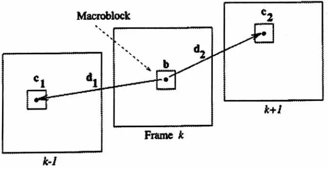
52). B frames (bi-directional
orinterpolated
images)
are codedusing interpolative coding between
a past and a
future frame (which
canbe I
or
P
frames).
The
signalto
be
reconstructedis
obtainedby
adding
a
correcting
term
to
a
combinationof a past and a
future
referenceframe. This is
shown
as
follows:
Macroblock
cl
41
Frame k
[image:19.568.129.458.398.568.2]k~I
These frames
provide
the
highest
amount ofcompression.
Bi-directional
prediction alsodeals
wellwith
just
uncoveredareas.
These
areas are notpredictable
from
the
past referenceframe,
but
can
be
predictedfrom
the
future
referenceframe.
The
effect of
noiseis
reduced
by
the
averagebetween
the
past
andfuture
reference
frames.
Errors do
notpropagate
if
the
B
frame
is
coded
with referenceto
an
I
frame.
"Increasing
the
numberof
B-pictures between
referencesdecreases
the
correlationof
B-pictures
with
the
references aswell
asthe
correlationbetween
the
referencesthemselves"
(LEGALL91 52). Reference Frames
are
usually
spaced at 1/10*second
intervals for
this
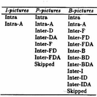
reason.The
following
figure
shows
the
available macroblock
types
in
MPEG-1
:
I-ficturt$
P-pietnres
B-pictvres
Intra
Iirtra
latra
Intra*
A
Intra-
A
Intra-
A
Intr-D
Inter-F
Inter-DA
latei^FD
latet-F
loter-FDA
Inter-FD
later-B
lotr-FDA
luter-BD
Skipped
Inter-BDA
later-I
InteMD
[image:20.568.196.364.286.454.2]Inter-IDA
Skipped
Figure 2
Macroblock types
in MPEG-1
(TEKALP95
443)
"Intra"
macroblock
do
notuse
motion estimationduring
their
compression,
while "Inter"frames do. Notice
that
I-pictures only
allow
"intra"
macroblocks.
MPEG
allows
spatially
adapted
quantization
by
allowing
a quantizer scale parameterMQUANT
to
be
used.
This
value
is
contained
in
the
MPEG header
for
I-pictures,
while
it is
transmitted
with
the
macroblock
for P
and
B
pictures.
Macroblock
types
listed
abovecontaining
the
-A switch usethe
current quantization
unsealed quantization matrix.
"It
has been
claimed
that
MPEG intra
mode provides30% better
compression
comparedwith
JPEG
due
to
adaptivequantization"
(TEKALP95
444).
The
subscript
"D"
indicates
that
the
DCT
ofthe
prediction
errorwill
be
coded.
The
subscript
"F"
indicates
that
forward
motion
compensation
is
to
be
used.
The
subscript "B"indicates
backward
prediction with
motioncompensation.
The
subscript
"I"
indicates interpolated
prediction with motion compensation.
In
this
caseboth
afuture frame
and a previousframe
areused
as
references.
This
is
shown
in
the
figure labeled
"MPEG-1
bi-direction
prediction".A
macroblock
is
coded as"skipped"
if
the
block
in
the
samelocation from
the
previous
frame is
to
be
used.
No
otherinformation
needsto
be
sentin
this
case.
It
is
highly
probable as a result ofthese
three
types
of
frames
that the
decoding
orderwill
differ
from
the
encoding
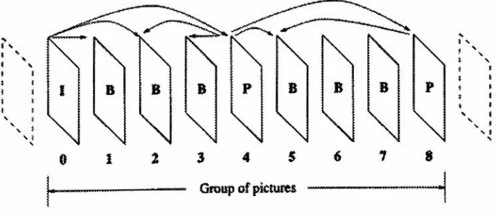
order.The MPEG
application
determines
the
proper sequenceof
I, P,
andB
frames.
A
sequence ofthese
frames
that
is
repeatedthroughout
anMPEG file is
called agroup
of pictures.
For
examplefast
random access requires moreI
frames,
whilebetter
compressionis
obtained
by
using
moreB
frames.
These
trade-offs
will
be
examinedin
this
project.
A
possiblegroup
of picturesis
shown asfollows:
NNN
2
3
4
5
[image:21.568.123.481.455.611.2]
-Group
of picturesThis group
of pictures couldbe
encoded
in
the
order
0, 4, 1, 2, 3, 8, 5, 6,
7
or0, 1, 4, 2, 3,
8, 5, 6,
7.
Motion
estimation
is
required
for
the
coding
ofP
and
B
frames.
This
technique tries
to
find
the
best matching
macroblock
in
the
availablereference
frames.
B frames
usebi-directional
prediction
that
is
also
known
as motion compensatedinterpolation,
whileP
frames
are
alwayscoded
using
forward
prediction.
B frames
can alsobe
coded
by
only using
one
referenceframe.
Motion
estimationextracts
the
motion
information from
the
videosequence.
One
motion vectoris
calculated
for P frames
and single reference
B
frames,
whiletwo
motion
vectors are usedto
codeinterpolated B
frames.
The MPEG
standarddoes
notspecify
the
motion estimationtechnique to
be
used.
As
aresult
this
portion
ofthe
code canbe
varied.
One
popular
choiceis
the
mean-absolute
difference
(MAD)
block-matching
technique.
In
this technique the
motion vectoris
obtainedby
minimizing
the
following
costfunction:
AM^^>s^2^aX!^alTO>)-G(''
+
A^
+
*')|
where:
F(i,j)
- representsa
(m
xn)
macroblockfrom
the
current
frame,
G(i,j)
- representsthe
samemacroblockfrom
a referenceframe (past
orfuture),
(dx,dy)
- a vectorThere
are several
algorithmsfor minimizing
this
cost
function.
The
algorithm
chosen can affectthe
results
obtained
andthe
compression
speed.
The
motion
vector
found indicates
the
distance
between
the
actual
andthe
reference
blocks. The
error
terms
between
the
actual andthe
referenceblock
arethen
calculated and encoded
using
aDCT based
technique.
16x16
macroblocks werechosen
asthe
basic
unit
for
motion-compensation.
The
16x16
areais
the
least
common multipleof
8x8
blocks,
given
the
normal
4:2:0
chroma ratio.
This
chromaratio means
that the
resolution ofthe
chromanance
(color)
channels
of acolor
image have half
the
number of
samplesin
the
horizontal
and
vertical
directions
asthe
corresponding luminance
channel.
The
16x16
area also provides agood
balance between
motion compensated predictionaccuracy
and sideinformation
overhead andcomplexity (MPEG-2 FAQ).
1.2.2
Spatial
Redundancy
Reduction
The
still-image and prediction error signalsboth have high
spatialredundancy.
Many
coding
techniques
existto
reducethis
spatial redundancy.
"Transform
coding
techniques
with acombination of
visually
weighted scalar
quantization and run-lengthcoding have been
preferred
because
the
DCT
presents acertain
number
ofdefinite
advantagesand
has
arelatively
straightforward
implementation"
(LEGALL91
54).
The
advantagesare
the
following:
The
DCT is
an
orthogonaltransform,
which meansit
can
be
transformed
into
the
frequency
domain
and actedupon
by
afilter
(quantization)
table.
An
8x8 block
of
pixels
is
sufficientto
calculate64
transform
coefficients.
The
DCT is
the
best
of
the
orthogonaltransforms
with acorresponding fast
algorithm
providing
a
very
close approximationto
the
optimalfor
alarge
class of
images.
The
type
of spatialredundancy
reduction consists ofthree
basic
steps:
the
discrete
cosinetransform,
quantization,
andentropy
coding.
These
stepswill
be described in
greaterdetail later in
the
thesis.
1
.2.3MPEG
compression and
Decompression
Block
Diagrams
I Frame
")
Color
Space
Converter
")
RGB->
YUV
FDCT
*
Quantization
)
Entropy
encoder
Compressed Data
10001110000....">
P/B Frame
->
Color
Space
Converter
RGB->YUV
r>
Error
terms
->
FDCT
Motion
estimator
</
Entropy
encoder
[image:25.568.62.550.73.464.2]Compressed Data
00111100101...
Figure 4 Block
Diagram
of
the
MPEG-1
Encoder
(LAPLANTE96
152)
To
compress a color
image it is
first
transformed
into
the
YUV
format.
Each
image
then
Bit
Stream
)
Buffer
Picture
type
If
Quanuzei
parameter
1
VLC
and
FLC
decoder
anddemultiplexer
^
")
Inverse
quantizer
)
IDCT
Inter/In
traPrevious
picture store
f
Write
future
Write
previous
-)
Future
picture storeMotion
compensation predictor
AAA
Picture
type
Video Out
t
->
Inter/
Intra
Figure
5 Block Diagram
of
the MPEG-1 Decoder
(LAPLANTE96
153)
1.3 Detailed Explanation
of
MPEG Compression
1
.3.1
Color
Space
Converter
This
part ofthe
algorithm convertsthe
input frames into
the
correct color
spacefor
the
MPEG-1
encoder.
The
encoder usesthe
YCbCr
color
space,
whichis
acolor
space with one
luminance
channeland
two
chromanance channels.The
chromanancechannels
have
half
the
[image:26.568.72.558.53.419.2]a
4:2:0
chroma
format.
The
following
table
lists different
chromaformats
with
pixeldimensions
of720
pixels/line x
480 lines/frame:
Chroma
Format
Y
samples/line
Y
lines/frame
C
samples/line
C
lines/frame
Horizontal
subsampling
Factor
Vertical
subsampling
Factor
4:4:4
720
480
720
480
none
none4:2:2
720
480
360
480
2:1
none4:2:0
720
480
360
240
2:1
2:1
4:1:1
720
480
180
480
4:1
none4:1:0
720
480
180
120
4:1
4:1
1.3.2
I Frame
Coding
1.3.2.1
FDCT
The
first
operation
performedis
the
DC
shift operation.All
this
operationdoes is
subtract
128
from
all
the
pixel valuesin
the
pixelblock. This
changesthe
range of pixel valuefrom 0
-255
to
-128-127.
This
is done
sothat
after
the
discrete
cosinetransform
(DCT)
the
valueswill
be
in
the
correct rangeto
be Huffman
codedby
the
standardDC
andAC
table to
be
discussed later.
The
next operationis
the
DCT transformation,
whichtransform the
8x8 block
of pixels
into
an
8x8
block
ofDCT
coefficients.This block
representsthe
amplitudes ofvarious
frequency
components
in
the
block
ofthe
originalimage.
The first
element ofthe
first
row
is
the
DC
elements
in
the
8x8
block
of
DCT
coefficients
provide
the
amplitudes
of
increasingly
higher
frequencies
as you
godown,
andto
the
right
in
the
block.
The DCT is
aseparable
algorithm
sothat
the
two-dimensional
processcan
be
divided
into
two
one-dimensional
processes,
as shownin
the
following
expressions:
SY
^
C(")^J^C(V)
where
2
j=o[t=o
2
C(ii)^
F(m,v)
=2,gOcos|
z
>=0c?0v)=
2^^^/0^)cosi
(2
+
16
cos
(2J
+
1)U7T
16
(2j
+
l)ux
16
(2
+
16
The DCT
procedure uses
these
expressions
to
perform
the
transform.
The inverse DCT
operation
uses
the
following
equation
to
perform
its
operation:
1
7 7/(U)
=-Xc(w)C(v)F(M,v)cos4
U=Q y=0(2/
+
16
cos
\2j
+
16
1.3.2.2
Quantization
Quantization
operatesby dividing
eachof
the
64
coefficients
in
the
DCT block
by
the
corresponding
value
in
the
quantization
matrix,
andthen
roundsthe
result.
This has
the
effect
ofcausing any
result
less
than
0.5
to
be
roundedto
zero.
These leads
to
compression when
these
F(w,v)
+
ifF(u,
v)
>0
if
F(u,
v)
<
0
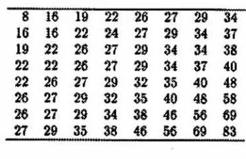
The
standard quantization
matrixis
constructedto
moreheavily
quantizecoefficients
that
are notas
perceptible
by
the
human
visual system
Many
ofthe
high
frequency
componentswill,
as aresult,
be
equalto
zero,
thus
providing
the
opportunity
for
compression.
The
standard quantizationtable
is
shown asfollows:
8
16
IS
22
26
27
29
34
16
16
22
24
27
29
34
37
19
22
26
27
29
M
34
38
22
22
26
27
29
34
37
40
22
26
27
29
32
35
40
48
26
27
29
32
35
40
48
68
[image:29.568.176.382.53.187.2]26
27
29
34
36
46
56
69
27
29
35
38
46
56
69
63
Figure 6 MPEG default intra
quantization
matrix
The
values
in
the
8x8
matrixare
then
reorderedin
a
zigzag
order.
This has
the
effect
oforganizing
the
coefficientsinto
an order
ofincreasing
frequency.
This
increases
the
chance
that
list
[image:29.568.188.367.332.448.2]0
1
5
6
14
15
27
28
2
4
7
13
16
26
29
42
3
8
12
17
25
30
41
43
9
11
18
24
31
40
44
53
10
19
23
32
39
45
52
54
20
22
33
38
46
51
55
60
21
34
37
47
50
56
59
61
35
36
48
49
57
58
62
63
1.3.2.3
Huffman
Entropy Encoding
This
processtakes
the
coefficients and compressesthem
in
alossless
fashion.
This
means
that these
coefficientscan
be
uncompressed
withoutlosing
any
information.
This
compressedbit
stream
is
then
sentto the
output
MPEG
file.
This
processis described
asfollows:
The DC
component
is
encodedby
first subtracting it from
the
DC
component ofthe
previous
block
(DPCM)
andencoding
the
difference
by
using
a
DC
Huffman
codetable.
The
nonzeroAC
values
are
first described
by
the
8-bit
number:
I
=NNNNSSSS. The S-bits define
acategory
from
1
to
Category
AC
Coefficient Range
1
-1,12
-3, -2,2,
3
3
-7, ...,-4,4, ...,74
-15, ...,-8,8,...,
15
5
-31, ...,-16,16,
...,316
-63, ...,-32,32,
...,637
-127, ...,-64,64, ...,127
8
-255, ...,-128,128,
...,2559
-511, ...,-256,256,
...,51110
-1023, ...,-512,512, ...,1023
The four N-bits
givethe
run
length
of
zero coefficientssince
the
last
nonzerocoefficient.
If
this
number
of zerosis
greaterthan
15,
a
value of240
is
usedfor
I repetitively
untilthe
number
ofzeros
becomes
less
than
15. The
value
1
=0
representsthe
end of all nonzerovalues
for
the
block.
The
value ofI
is
then
encodedby
using
another
Huffman
codetable
designed
for AC
components.
This Huffman
code
is
then
followed
by
the
value ofthe
quantizedDCT
coefficientexpressed
by
the
category bits. The
two
Huffman
codes(DC
andAC)
are generatedby
using
statistics gathered
which
tell the
frequencies
of each code occurring.
The corresponding Huffman
code
is
generated
sothat
frequently
occurring
codes are representedin
fewer
bits.
The Huffman coding step
mentioned
abovein
the
discussion
ofthe
MPEG
compressionalgorithm
is
a
lossless coding
step.
This
means
the
noinformation is lost
during
the
compression ofthe
data.
This step
is
basically
a
big
lookup
table
wherea
certainnumber
of
input bits
aretranslated
into
a certain number of output
bits. This
lookup
table
is
generatedby
observing
the
probability
ofthe
different
input
bit
patternsoccurring in
the
data
stream.
The
goal of
Huffman
coding is
to
code
the
mostfrequent
input bit
patternswith
the
least
number of
bits.
As
an
exampletake
asmall
group
ofinput
'messages'with
known
probabilities
ofoccurring in
the
input data
stream:
Message
Probability
A
0.30
B
0.25
C
0.20
D
0.10
E
0.15
Huffman
code constructionbegins
by
summing
the two
least probability
values,
andrewriting
the
list. Note
that
the
initial list is
orderedwith
decreasing
probabilities.
This
process
is
continued
left
A
.30 .30".45
l
?B
.25 .25 .30C
.20^
i .ZJ
E
.15 .20D
.10.55
.45
Huffman
codes arethen
assign
from
right
to
left.
The right
most column
is
markedwith a
zero anda
one.
The
columnto the
left is formed
by
expanding
the
codethat
resulted
from
the
sum of
the two
least probability
values.
To
do
this
a zero
is
addedto the
right
ofthe
present
Huffman
codefor
the
greater of
the two
probability
values,
and a oneis
addedto the
right
ofthe
presentHuffman
codefor
the
lower
ofthe two
probability
values.
The
other
Huffman
codes are
just
copied asis.
This
process
in
then
repeated.
The
final
Huffman
codesare shown
in
the
left
mostcolumn.
This
processis
shown
asfollows:
A
00
.3000
.30 rl .450
.55B
01
.2501
.2500
30J
1
.45C
ll
.20-10
.25<
01
1
.25
E
100
.15I"
J
11
.20D
101
.10Assuming
that
probabilitiesfor different inputs
into
the
Huffman
coder can
be
determined,
the
Huffman
lookup
table
cantherefore
be
generated.
These
probabilities can
be
determined
by
probabilities can
alsobe
determined
by
observing
the
frequencies
of
the
symbolsin
the
data
being
processed.
This
allows an optimized
Huffman
table
to
be
constructed.
This may
requiretwo
passesover
the
data,
one
to
gather
statistics
andone
to
compressthe
data.
This
resultsin
slowercompression,
but possibly
a
higher
compression ratio.
1.3.3
P/B Frame
Coding
1.3.3.1
Motion Estimator
1
.3.3.1.1
The
Block-Matching
Method
Block matching is
the
most popular methodfor
motion estimationdue
to
its lesser
hardware
complexity,
and
it's
now
widely
available
in VLSI. Block matching
finds
the
best
motion
vector estimate
by
apixel-domain search procedure.
The
general concept ofblock matching is
shown
in
the
following
figure:
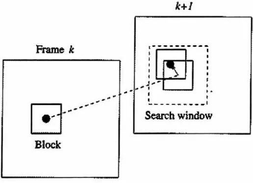
Frame
k
'' *
"
[image:34.568.132.390.406.593.2]Block
"The
displacement for
a pixel
(ni,
n2)
in
frame k (the
present
frame)
is determined
by
considering
an
(m
x
n) block
centered about
(ni,
n2),
andsearching frame k
+
1 (the
searchframe)
for
the
location
of
the
best-matching
block
of
the
samesize"
(TEKALP95 101).
The
searchis
typically
limited
to
an area
of(m
+
2p)
x
(n
+
2p)
which
is
calledthe
search window.
Typically
a
16x16
macroblock
is
used and
p
=6.This
is
shown
by
the
following
figure:
a+lip
m+ltp
Figure
8 The
search
area
in
block-matching
techniques
for
motion vector
estimation
(FURHT95
148)
Block-matching
algorithms
differ in
the
matching
criteria andthe
searchstrategy.
The
matching
criteriais
aformula
which gives an errorvalue
as aresult,
giventhe
motion vector and
necessary
pixel valuesas
inputs. The
search
strategy is
a
methodthat
searchesfor
the
block
that
minimizes
this
errorvalue.
Once
the
desired block is
found,
the
vector
is
encoded
in
the
MPEG
stream
along
withthe
pixel
differences between
the
two
macroblocks.
These
pixel
differences
are
[image:35.568.111.447.215.376.2]between
the two
macroblocks should
be
close
to
aminimum, the
resulting
errorterms
will
have low
values and spatial
energy.
This
resultsin
ahigh
amountof compression.
1
.3.3.1.2Block
Matching
Criteria
1.3.3.1.2.1
The Mean-Absolute Difference
(MAD)
(FURHT95
148)
The
Mean-
Absolute Difference
(MAD)
is
defined
as:
MAD{dx,
dy)
=XZ'n
Y^,i\F^
?>
~G(<
+
dx^
+
M
where:
F(i,j)
- represents a(m
x
n)
macroblock
from
the
currentframe,
G(i,j)
- representsthe
samemacroblock
from
a referenceframe (past
orfuture),
(dx,dy)
-a
vectorrepresenting
the
search
location.
The
searchspace
is
specifiedby:
dx
anddy
in
the
range{-p,+p}
In
typical
applicationsm=n=16
andp=6,
the
MAD function
becomes:
MAD(dx,
dy)
=-i-XL
X
]=-*
1
F^
/>~
G(*
+
This
cost
function
is
the
most popular
choicefor VLSI implementations
andis
usedfor
video applications.
The
search
strategy looks
for
a
minimumvalue.
1.3.3.1.2.2
The Mean-Squared Difference
(MSD)
(FURHT95
149)
The
Mean-Squared
Difference
(MSD)
is defined
as:
MAD(dx, dy)
=YZ'nn Y^-ln
iF^
f>
~G
+
dx^'
+
^
mn
The
searchstrategy looks for
aminimum value.
1.3.3.1.2.3
The Cross-Correlation Function
(CCF)
(FURHT95
149)
The
Cross-Correlation Function
(CCF)
is defined
as:
Y^F(UJ)G(i
+
dx,j
+
dy)
CCF(dx,dy)
=' j
CL^F\Uj))y\Y.Y,G\i
+
dx,j
+
dy)f
The
searchstrategy looks for
a minimum value.
The MSD
andCCF
can
be
more efficientthan
the
MAD
function,
but
are
too
complex
for
1.3.3.1.2.4
The
Maximum
Matching
Pel Count
(MPC)
(TEKALP95
103)
The Maximum
Matching
Pel Count is defined
as:fl
if\s(nl,n2,k)-s(nl +
dx,n2
+
dy,k
+
l)\<t
T(nl,n2;dx,dy)
=i
v J
0
otherwisewhere
t
is
apredeterminedthreshold
MPC(dx,
dy)
=X
r<>L
nl\dx,
dy)
(M2)
The
searchstrategy looks for
a
maximum value.1.3.3.1.3
Block
Search
Strategy
1.3.3.1.3.1
The
exhaustive search algorithm(FURHT95
150)
"The
exhaustive search algorithmis
the
simplestbut
computationally
intensive
search
method,
whichevaluatesthe
costfunction
atevery location in
the
searcharea"
the
MSD
costfunction
is
used
to
estimate
the
motionvector,
it
would need
to
be
evaluated169,
(2p+l)2where
p=6,
times
for
each macroblock.
1.3.3.1.3.2
The
three-step-search
algorithm(FURHT95
150)
The
three-step
search algorithmfirst
calculatesthe
costfunction
atthe
center and eightsurrounding locations in
the
searcharea.
The location
that
resultsin
the
smallest
costfunction
becomes
the
centerlocation
for
the
nextstep.
The
search rangeis
reducedby
half. For
p=6,
the
step
size
(distance
from
the
center
location
to the
surrounding locations
to
be
tested)
is
3
for
the
first
iteration,
2 for
the
second,
and1 for
the
third.
The
smallest costfunction
resultfound becomes
[image:39.568.129.441.361.632.2]the
chosenblock matching
location.
This
is
shownby
the
following
figure:
The
total
number of
computations
ofthe
cost
function is: 9
x3
-2
=25,
which
is
much
better
than
the
exhaustive search
algorithm.
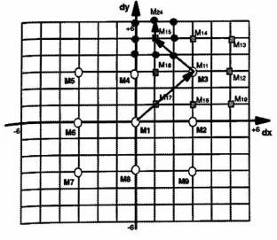
1.3.3.1.3.3
The 2-D logarithmic
search algorithm
(FURHT95
152)
This
algorithm uses
a costfunction,
typically
the
MAD
costfunction,
to
perform
alogarithmic
2-D
search
along
a virtualdirection
of minimumdistortion
onthe
data
withinthe
search area.
The
following
figure
shows an example ofthis
algorithm:
*J
\
3
.3,4
i
,4
It
.,.,
4
3
L2b
M2
[MS
t,
(3
A
%
3
iu ir
J&
r
7
*K
Lza
M3
J
tl
M
r
[Ml
'r
2a
r)2bm
t.
M6
dx
[image:40.568.130.431.302.560.2]Step
1
The MAD function is
calculated
for
M(0,0),
and comparedto
athreshold.
If
the
valueis below
the
threshold,
the
desired location is
found
and
the
searchis
complete.
Assume
that
this
is
the
caseany
time
aMAD
function is
calculated at
alocation
for
the
remainder of
alocation. This
meansthat
the
algorithm
stopswhen
alocation is found
wherethe
MAD
is below
the threshold.
Step
2a
The
nextfour
costfunctions, Mi(4,0),
M2(0,4),
M3(-4,0),
andM,(0,-4)
are calculated.If
the
minimum
of
these
4
valuesis less
than
M(0,0)
go
to
step
2b.
Otherwise,
go onto
step
3.
Step
2b
Assuming
that the
minimumin
the
previousstep
wasfound
at
Mi,
then the
surrounding
positionsM5(4,4)
andM6(4,A)
are calculated.The
minimum ofthese
to
locations
is
usedin
the
nextstep.
Step
3
Assuming
that the
new minimumlocation is
M5(4,4)
as
shownabove,
steps2a
and2b
are repeatedwith
the
step
sizedivided
by
2.
The step
size
is
divided
by
2 again,
steps
2a
and
2b
are
repeated,
and
the
algorithm
endswith
the
minimum
location
of
the
final
tests
being
the
result.
1.3.3.1.3.4 The
conjugate
direction
search algorithm
(FURHT95
153)
The
principle of
this
search method
is
shown
by
the
following
figure:
[image:42.568.185.392.272.498.2]Y
*
Figure 11 The
principle
of
the