Rochester Institute of Technology
RIT Scholar Works
Theses Thesis/Dissertation Collections
8-1-2008
Using the cell processor as an offload streaming
assist for sessionization of network traffic for cross
packet inspection
John Martellaro
Follow this and additional works at:http://scholarworks.rit.edu/theses
This Thesis is brought to you for free and open access by the Thesis/Dissertation Collections at RIT Scholar Works. It has been accepted for inclusion in Theses by an authorized administrator of RIT Scholar Works. For more information, please [email protected].
Recommended Citation
Using the Cell Processor as an Offload Streaming Assist for
Sessionization of Network Traffic for Cross Packet
Inspection
by
John Anthony Martellaro
A Thesis Submitted in Partial Fulfillment of the Requirements for the Degree of Master of Science in Computer Engineering
Supervised by
Dr. Roy Melton
Department of Computer Engineering Kate Gleason College of Engineering
Rochester Institute of Technology Rochester, NY
August 2008
Approved By:
_____________________________________________ ___________ ___
Dr. Roy Melton
Primary Advisor – R.I.T. Department of Computer Engineering
_ __ ___________________________________ _________ _____
Dr. Muhammad Shaaban
Secondary Advisor – R.I.T. Department of Computer Engineering
_____________________________________________ ______________
Mr. Michael Schiller
Thesis Release Permission Form
Rochester Institute of Technology
Kate Gleason College of Engineering
Title: Using the IBM Cell Processor as an Offload Streaming Assist for Sessionization of Network Traffic for the Application of Cross Packet Inspection
I, John Anthony Martellaro, hereby grant permission to the Wallace Memorial Library to
reproduce my thesis in whole or part.
_________________________________ John Anthony Martellaro
Dedication
I dedicate this to Alex Matzner.
Acknowledgements
I would like to thank Mr. Michael Schiller, Dr. Roy Melton, and Dr. Muhammad Shaaban for all
their guidance. In addition, I am extremely grateful for the support and facilities offered by the
UMIACS Laboratory of Telecommunication Sciences as well as the knowledge obtained from
Abstract
Deep packet inspection is a means of ensuring network security and eliminating
malicious activity by scanning the contents of packets for threats. Deep packet inspection
analyzes each packet on an individual basis to ensure that it does not exhibit a malicious
signature. As network link speeds increase as well as the number of threats, it becomes
increasingly difficult to scan for threats in real time. As a result, costly and very specialized
hardware implementations were designed to handle the demand of scanning packets at high link
rates.
It is common that packets from the same session arrive out of order at inspection points.
As a result it is possible that a signature can exist across the boundaries of two different packets
and a scanner will miss a potential threat. The IBM Cell Broadband Engine was selected to
group packets of the same session together prior to scanning because it offered a cost effective
solution compared to specialized hardware. By having the ability to scan across packet
boundaries one achieves a greater degree of threat detection and characterization of traffic.
This thesis investigates the performance achieved by using the Cell processor as a
preprocessor to group packets from the same network sessions together for scanning across
packet boundaries. The implemented sessionizer was capable of processing network traffic at a
worst case rate of 3 Gb/s and a best case of 20 Gb/s with four out of eight available synergistic
Table of Contents
Thesis Release Permission Form ... ii
Dedication ... iii
Acknowledgements... iv
Abstract ... v
Table of Contents... vi
List of Figures ... viii
List of Tables ... x
Glossary ... xi
Chapter 1 Introduction... 1
Chapter 2 Background ... 4
2.1. Packet Inspection ... 4
2.2. Overview of the Cell Architecture... 6
2.3. Cell Accelerated Packet Inspection ... 8
2.4. Chapter Summary ... 10
Chapter 3 Design ... 11
3.1. Overview of the Hardware Architectural Design... 12
3.1.1 High Performance Servers ... 13
3.1.2 High Performance Networking ... 14
3.1.3 Low Cost Sony PlayStation 3 Implementation... 15
3.2. Overview of the Software Design Considerations ... 16
3.2.1 Operating System... 16
3.2.2 Session Data Design Consideration... 17
3.2.3 Streaming Framework... 18
3.2.4 Memory Management Scheme... 18
3.2.5 Session Aging Scheme... 19
3.2.6 Testing Environment ... 20
Chapter 4 Implementation ... 21
4.1. Software Implementation... 21
4.1.1 Power Processing Element ... 22
4.1.2 Synergistic Processing Elements ... 23
4.1.3 Session Data Structure ... 24
4.1.4 Streaming Framework ... 32
4.1.5 Session Aging Scheme... 38
4.2. Testing... 39
4.3. Chapter Summary ... 40
Chapter 5 Results and Discussion ... 41
5.1. Synchronized Shared Buffer Implementation ... 41
5.1.1 Single SPE Baseline... 42
5.1.2 Multiple SPE Scaling... 45
5.1.3 Local Store Optimization Results... 48
5.2. Asynchronous Multi Distributed Buffer Implementation ... 49
5.2.1 Single SPE Baseline... 49
5.2.2 Multiple SPE Scaling... 50
5.2.3 Commercial System Test ... 53
5.3. Chapter Summary ... 54
Chapter 6 Conclusions and Future Work ... 55
6.1. Conclusions... 55
6.2. Future Work ... 56
6.2.1 Hashing ... 57
6.2.2 Session Aging and Retrieval... 57
6.2.3 Different Protocols ... 58
6.2.4 Integration and Future Architectures ... 58
List of Figures
Figure 1: Cell Processor Block Diagram...7
Figure 2: Session Data Structure ...25
Figure 3: TCP Modified Session Data Structure ...28
Figure 4: Memory Aligned Sessions ...29
Figure 5: Memory Storage Example ...30
Figure 6: Memory Allocation Example...31
Figure 7: Modified TCP Storage Space...31
Figure 8: Streaming Framework Flow ...34
Figure 9: Shared Memory Buffer ...36
Figure 10: Distributed Buffer Model...37
Figure 11: Synchronized Buffer with 1 SPE and No Optimizations with 2048 Sessions ...43
Figure 12: Finer Resolution of Figure 9 from 1200 - 1500 Byte Packets...43
Figure 13: Synchronized Buffer with 1 SPE and SDS Optimization with 2048 Sessions...44
Figure 14: Finer Resolution of Figure 5 from 1200 - 1500 Byte Packets...45
Figure 15: Synchronized Buffer with 2 SPE and No Optimizations with 4096 Sessions ...46
Figure 16: Synchronized Buffer with 3 SPE and No Optimizations with 6144 Sessions ...47
Figure 17: Synchronized Buffer with 4 SPE and No Optimizations with 8192 Sessions ...47
Figure 18: Synchronized Buffer with 2 SPEs and SDS LS Optimization with 4096 Sessions ...48
Figure 19: Asynchronous multi-buffer with 1 SPE and SDS LS Optimization with 2048 Sessions...50
Figure 20: Asynchronous multi-buffer with 2 SPEs and SDS LS Optimization with 4096 Sessions ...51
Figure 21: Asynchronous multi-buffer with 3 SPEs and SDS LS Optimization with 6144 Sessions ...52
List of Tables
Table 1: Power Processing Element Tasks...23
Glossary
BIF Broadband Interface - Connects two Cells chip together
CBEA Cell Broadband Engine Architecture
DPI Deep Packet Inspection
EIB Element Interconnect Bus
ISA Instruction Set Architecture
LS Local Store – 256-KB chunk of memory in a SPE
MFC Memory Flow Controller
MIC Memory Interface Controller
MMU Memory Management Unit
OFED Open Fabrics Enterprise Distribution
POWER Performance Optimization With Enhanced RISC
PPE Power Processing Element
PPU Power Processing Unit
PS3 PlayStation 3
RAM Random Access Memory
SIMD Single Instruction Multiple Data
SPE Synergistic Processing Element
SPU Synergistic Processing Unit
Chapter 1
Introduction
Packet inspection is a method of scanning network traffic for security threats and
malicious activity by analyzing the contents of packets. Networks utilize a combination
of traffic inspectors called network intrusion detection systems, spam filters and firewalls
to take preventive security measures against harmful network traffic. At the root of the
three systems mentioned is a packet inspection engine that characterizes whether network
traffic is suitable to enter the network or whether it should be denied entry.
A packet is a discrete unit of memory which is used by networks to transfer data
from one point to another point and is composed of two parts: the header and payload.
The packet header contains the necessary information for delivery from source to
destination, such as port and internet protocol numbers. The payload of a packet resides
after the header and is the actual data that is being transferred.
Depending on the size of the data to be transferred it will be chunked into
multiple payloads for delivery by multiple packets. An example would be if a data
source is 3000-bytes then three 1000-byte payloads could be formed. The three packets
would be sent from the source in order, but due to network delivery could arrive at the
destination out of order in any possible combination. If the packets need to be reordered,
the destination system will then order the packets accordingly to reconstruct the original
data transferred.
Deep packet inspection is a technique of analyzing each packet’s header and
payload on an individual basis to ensure that it does not contain a malicious signature.
increase. In addition, as time progresses the number of malicious network signatures also
increases. To be able to scan traffic for a growing number of threats on increasingly high
data link networks, costly and specialized FPGA and ASIC solutions have been
developed. Software solutions do exist, but they cannot process high link rates; however
they offer great flexibility in scanning different parameters. FPGA and ASIC solutions
are very fast, but do not have the same scanning flexibility that software can provide.
It is possible that packets from the same session arrive out of order at inspection
points. A problem that can occur is that a signature exists across the boundaries of two
different packets and a scanner will miss the threat because only part is capable of being
scanned. To complicate matters, when packets arrive out of order it makes it a very
challenging problem to scan packet boundaries for complete signatures. Current
technology solutions cannot account for real-time out of order packet scanning because of
the resources it requires.
The IBM Cell Broadband Engine was selected to overcome this problem by
grouping packets of the same session together prior to scanning. The Cell processor
offers a cost effective solution compared to specialized hardware. In addition, the Cell
offers the ability to have the flexibility of scanning parameters by software with the
speeds achievable by FPGAs and ASICs. Having the ability to scan across packet
boundaries allows a greater degree of threat detection and characterization of traffic than
traditional packet scanners. Scanning across packet boundaries is an advanced form of
inspection called cross packet inspection. This research advances deep packet inspection
The next chapter focuses on the background of packet inspection and how it
applies to sessionization. The Cell architecture is explained as well as it lends itself to
the sessionization problem. The remainder of the thesis focuses on design,
implementation, results, and conclusions. The design chapter discusses a high end
commercial design, and a low cost design using a widely available gaming console which
has a Cell processor. The implementation chapter focuses primarily on the software of
the low cost sessionization design. The results chapter discusses how well the Cell
processed simulated network traffic. Finally the conclusions and future work chapter
describes the performance gains of the Cell architecture with sessionization and how this
Chapter 2
Background
This chapter discusses the background and importance of packet inspection
technologies as they relate to network security. The limitations of deep packet inspection
are discussed and provide a basis for why cross packet inspection is a better method for
scanning packets than traditional packet scanners. In addition, the Cell architecture is
described in detail focusing on four main components of its design. Finally the last
section illustrates why the Cell processor design lends itself for a flexible, fast and cost
effective solution for performing sessionization.
2.1. Packet Inspection
There is a great demand for technologies that monitor network traffic for
malicious activity such as viruses, worms and harmful network attacks. Network traffic
is monitored by analyzing the contents and characteristics of packets corresponding to a
specific network connection. Packets pass through a firewall which keeps track of the
state of a connection such as ports and internet protocol addresses. In addition the
firewall has an intrusion detection and prevention scheme which determines how the
packet should be handled. If the packet does not have the signature of something
malicious then it is free to pass in the network. However, if the packet resembles
characteristics of a known threat then it is detected and prevented from continuing to pass
through the network.
The first firewalls in the early 1990s were very simple packet filters which only
packet. Shallow packet inspection gives very limited knowledge of the threat of a packet.
As time progressed firewalls became more sophisticated and began to analyze the
payloads of each individual packet. This form of scanning the payload, called deep
packet inspection, offers significantly more reliability in detecting threats. Each packet
payload can be scanned for a known threat against a dictionary of keywords.
As network speeds transitioned from 100 Mb/s to 1 Gb/s to 10 Gb/s, it became
increasingly more difficult to scan for threats in real time. It becomes nearly impossible
for a traditional computer to keep up with scanning and processing of all packets at 10
Gb/s. As a result very specialized ASICs and FPGA network processors were designed
to handle the scanning of packets for increasing network speeds. These specialized
designs are expensive ranging from low end solutions that start at fifty thousand dollars
to high end systems with price tags in the hundreds of thousands. A company by the
name of Procera Networks has a traffic monitoring solution that costs $800,000 to handle
10 Gb/s traffic [10]. While 10 Gb/s is the current standard, industry has already begun to
issue future standards for Ethernet to operate at 100 Gb/s in the future of a few years [11].
This ten times increase from 10 to 100 Gb/s will make it even more difficult to process
traffic and scan for threats [6].
The Cell processor is a uniquely designed multi-core heterogeneous architecture
with a tremendous amount of internal bandwidth. Instead of being able to transfer data at
gigabits per second, the Cell can easily perform direct memory accesses asynchronously
at tens of gigabytes per second across multiple specialized processors. The ability to
processors makes it a very attractive system for processing high speed network traffic
traditionally not possible by commercial of the shelf.
2.2. Overview of the Cell Architecture
The Cell Broadband Engine Architecture (CBEA) was a joint effort between Sony
Computer Entertainment, Toshiba and IBM to create a new high performance processor
that was cost effective and power efficient under a variety of different computationally
intensive workloads. The processor underwent development in early 2001 and is most
mostly widely recognized in the Sony PlayStation 3 gaming console which was released
during mid November 2006. While the gaming industry has a large demand for high
performance, the Cell can be found in a variety of other industries.
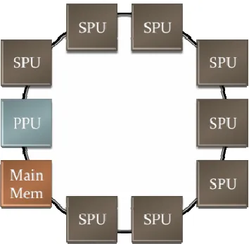
The Cell Architecture is a novel heterogeneous processor design that consists of
four main components that work together: one Power Processing Element (PPE), eight
Synergistic Processing Elements (SPEs), one Element Interconnect Bus (EIB) and one
Memory Interface Controller (MIC). The Cell is often referred to as a “system on a chip”
because it connects a generic processor with eight specialized processors over a high
speed ring interconnect. In Figure 1, there is an illustration of the architecture of the Cell
Figure 1: Cell Processor Block Diagram
The power processing element (PPE) is a generic stripped down version of a core
compliant power processor which is responsible for running the operating system and
performing the synchronization between the other synergistic processors. The PPE has a
software managed 512-KB L2 cache, as well as an Altivec engine. In many regards the
PPE acts as a watchdog for the other aspects of the system. In addition since the core
processor is a power pc, any previous code written for a power pc is compatible.
The real computational performance behind the Cell is leveraged from usage of
the eight Synergistic Processing Elements (SPEs) that exist per chip. SPEs are
specialized RISC processors with SIMD instructions, which have traits of both that
resemble a tradition central processor and digital signal processor. Each SPE has its own
256-KB chunk of memory called Local Store (LS) which is used for both data and
program instructions. In addition there are 128 registers, each 128 bits wide, for integer
and floating point SIMD operations. One of the most unique and important aspects of the
SPE is the Memory Flow Controller (MFC). The MFC consists of a DMA controller,
The SPEs, PPEs and main memory are all connected over a high speed four-lane
ring bus called the Element Interconnect Bus (EIB). The ring has two clockwise and two
counterclockwise rings which are directly connected to the MFC of each element. The
EIB is another very important aspect of the Cell because it efficiently manages all DMA
requests. The EIB has an arbiter that delegates the most efficient path around the ring for
each request. The Cell EIB has a peak theoretical aggregate bandwidth of 204.8 GB/s
across SPEs. In practice this peak bandwidth is difficult to achieve because there are a
variety of factors that affect performance such as memory alignment, DMA transfer size,
buffering techniques, synchronization methods and processor affinity. The bandwidth of
all SPEs accessing main memory is 25.6 GB/s - again subject to specifics of usage.
2.3. Cell Accelerated Packet Inspection
The internal bandwidth of the Cell processor is on an order of magnitude faster
than the highest current operating speed of network lines at 10 Gb/s. The Cell processor
is easily capable of transferring memory at gigabytes per second as opposed to gigabits
per second. The high internal bandwidth of the Cell as well as a fine controlled DMA
engine made it a suitable candidate for processing packets. It has been shown that the
Cell could perform deep packet content scanning of traffic with two SPEs at 10 Gb/s
using a deterministic finite automata approach [6].
A major advancement over deep packet inspection is to perform cross packet
inspection. Cross packet inspection is packet inspection in which a contiguous group of
packets belonging to the same unique network stream are scanned. Cross packet
one continuous flow. The Cell’s DMA engine is very capable of performing the memory
transfers needed for grouping packets for cross packet inspection.
Packets are transferred over a network in a variety of sizes. TCP network data is
typically between 40 and 1500 bytes in size. TCP data orders the packets by a sequence
number so that data can be reconstructed in order upon delivery. Deep packet inspection
engines are only scanning 40 to 1500 bytes of data at any given time. However, cross
packet inspection gives the ability to scan kilobytes to megabytes or more depending on
how large of a session is collected. Thus cross packet inspection offers a much larger
window of scanning, so fewer threats are missed.
If a malicious activity signature occurs across the boundary of two packets then a
deep packet scanner would miss the threat. However, if one were able to order all the
packets associated with a particular network flow or unique session then one could scan
across the boundaries of each individual packet and treat it as a large packet. The large
packet could then be fed to a packet scanner so that threats would not be missed. In
addition, this allows for full reconstruction and characterization of data.
Instead of being limited to the contents of single packets, one can now scan the
data across all the packets at once and characterize the activity in real time. This process
of storing all packets in order requires a high internal bandwidth and a fair amount of
memory. The Cell processor’s internal bandwidth capable of 25.6 GB/s makes it possible
to process much slower 10 Gb/s packets. In addition, it has enough space to track a
substantial number of unique session flows with a specified amount of memory allocated
2.4. Chapter Summary
This chapter has discussed the problem and limitations of current deep packet
inspection technology. Deep packet inspection is limited to a per packet inspection
which limits the amount of data that can be scanned. Packets sent in order can arrive out
or order at inspection points making scanning across boundaries impossible. The high
internal bandwidth of the Cell processor makes it possible to group same session packets
together so they can be scanned in order and perform a much richer threat detection
called cross packet inspection. This thesis investigates replacement of deep packet
inspection with cross packet inspection technologies, just as shallow packet inspection
Chapter 3
Design
This chapter discuses the design of two Cell based network sessionizers. The
design uses the high performance Cell processor systems available from IBM such as a
QS21 blade server. After the commercial blade server design is discussed, it is shown
that the system can be ported to an inexpensive and widely available Sony PlayStation 3
(PS3) gaming console that also utilizes a Cell processor for a low cost implementation.
The PS3 has less memory and fewer synergistic processors than the commercial system,
but the concepts and software design parallel the same implementation choices of the
high performance system. The PS3 design was implemented and used to collect all
results in this paper.
The high performance sessionization system design is composed of a hybrid
configuration that consists of a Cell blade server and an x86 server connected over high
speed infiniband cabling. The PS3 implementation lacks the second x86 server or the
high speed interconnect cabling. While the hardware configurations are different, the
software components are exactly the same. The sessionization software components are
broken into session data structures, streaming framework, memory management scheme,
session aging and Cell specific optimizations.
The session data structures are necessary for encapsulating network packets in a
manageable way. The streaming framework section explains the details of how to
process packets and store them. The streaming framework was implemented using two
models: shared and distributed memory model. Each of the streaming models is
efficient storage on the Cell. Session aging is the practice of freeing memory when a
session is ready for processing. Lastly, there are Cell specific optimizations that can be
implemented to enhance performance.
3.1. Overview of the Hardware Architectural Design
Sessionization of network traffic is a very broad topic because there are many
different protocols and fragmentation/retransmission issues that one has to consider. As a
result of this complexity, design choices were made that stripped away nonessential
details and focused on a narrow subset of the problem. The following sections focus on
the design of a commercial sessionization system that would be capable of processing
real-time encapsulated UDP or TCP traffic at high data rates. Issues of packet
retransmission/fragmentation are ignored.
Due to a limited budget and high cost of infrastructure needed for testing, a base
system was implemented that simulated traffic and lacked a real high speed link for
processing. The intent of this thesis is to prove that the low cost sessionizer could
process simulated traffic first to justify the further development and testing costs of an
actual sessionization system with high speed data links connected.
The following sections focus first on a commercial host system for delivering
high speed traffic to a Cell blade server. The Cell blade server is discussed as well as
how there are enabling technologies to connect a Cell server to another server at 10 Gb/s.
The I/O technologies include high speed interconnect cabling, and a short background on
This section ends with discussing the less complicated Sony PlayStation 3
implementation used for collecting results.
3.1.1 High Performance Servers
The current versions of the IBM Cell based blades only have a few gigabytes of
main memory on them. As a result, applications have to use memory as efficiently as
possible. In the case of sessionization, the system utilizes all of the available memory to
construct sessions in memory with as memory packets as possible. With traffic entering
the system at 10 Gb/s or approximately 1 GB/s memory becomes a scarce resource very
quickly. To overcome this memory problem a pre-buffer on another system becomes
extremely useful.
Any high performance x86-server with 64-GB of main memory or more would
greatly mitigate the memory buffer problem. A high performance server connected to a
Cell blade over a high speed network card that supports 10 Gb/s, which utilizes either the
Open Fabrics Enterprise Distribution (OFED) software stack, Message Passing Interface
(MPI), or similar technology, would make it possible to process traffic in real-time. The
Cell would then be responsible only for processing the packets it receives from the host
and performing the sessionization.
The benefit of this configuration is that the server could also be used to load
balance traffic from multiple sources to be used across multiple sessionization systems by
performing a very simple hash on the packets and assigning their hash to a specific Cell.
Depending on the desired performance needed, one could scale the system across
The host server is not necessarily a crucial element of the commercial sessionizer
design but is highly recommended because it provides options for load balancing,
extended memory, and also a rich testing environment. The host server could be used to
supply network snapshots to the Cell sessionizer. Having a host with much main
memory allows for long test scenarios that could be streamed to the Cell blade. By
having repeatable test scenarios and the ability to characterize data, the sessionization
system could be continually refined. The limited memory on the Cell makes it difficult to
test long trace files and still have memory available to sessionize.
3.1.2 High Performance Networking
This section discusses technology available to connect a Cell blade to another
server at 10 Gb/s. It is desirable to have the ability to stream input into the Cell faster
than the incoming rate of the buffering host server to ensure there is no packet loss. One
known solution is to use products provided by either Mellanox Technologies or Chelsio
Communications which make high-speed I/O cards that support high performance
networking at 10 Gb/s and above [12].
These cards are designed to utilize infiniband cabling and implement a TCP stack
in hardware which provides high bandwidth, low latency interconnect transfers between
systems. By having the TCP stack implemented in the card’s hardware, the amount of
CPU utilization required is drastically reduced compared to other transports methods
which do not utilize this technique. Keeping CPU utilization low allows the processor to
work on sessionization computations rather than to devote limited resources to I/O
Having the TCP stack in hardware allows use of a feature of the cards to perform
Remote Direct Memory Access (RDMA) across systems. RDMA is the ability to access
memory on a host via the network card with minimal CPU intervention. This feature is
an extremely useful because it eliminates the need to copy memory to a system and then
have the CPU process it. Instead, there is a “zero-copy” related to the RDMA, in which
the memory is just transferred without wasting CPU cycles. In the case of network lines
operating at gigabits per second performing zero copies via RDMA is very efficient
because it eliminates all of the extra copies traditionally incurred.
3.1.3 Low Cost Sony PlayStation 3 Implementation
Whereas the preceding sections established the groundwork for a full fledged
sessionization system capable of processing real network traffic, the purpose of this thesis
is to demonstrate that simulated traffic can be processed internal to the Cell as
justification for the future costs of developing a full-fledged system. The PS3 is a
gaming console that has a Cell processor in it that one can use for programming.
Compared to the high performance blade center, the PS3 lacks a some major
features. The QS21 blade center has 2GB of memory with two Cell processors connected
over a coherent interface. This allows the QS21 to have two PPUs and a total of 16 SPEs
to perform sessionization. The PS3 only has 256 MB of available memory with 1 PPU
and 6 available SPEs. While the Cell processor has 8 SPEs, only 6 are available on the
PS3 because 1 SPE is always disabled because it may have been damaged during the
fabrication process, and the other SPE is used by the PS3 hypervisor to manage the
Other than these hardware differences, the PS3 has the exact same Cell processor
that is found in a high performance blade server. The PS3 serves as a cost effective
solution for developing applications on the Cell without having the need to purchase a
blade server chassis and the individual blades to populate the server.
3.2. Overview of the Software Design Considerations
The most important aspect of this research is the software design. The Cell can be
a difficult architecture to program with certain design choices. Most of these design
choices concerned proper usage of the Cell’s DMA engine to transfer data as efficiently
as possible. In addition, synchronization of events is an important detail to keep the
system constantly processing data without stalling.
3.2.1 Operating System
Programming on the Cell processor is accomplished by utilizing the Cell Software
Development Kit (SDK). Cell blades run PPC versions of the Linux kernel. The OFED
and SDK require specific versions of the Linux kernel for their respective versions. One
cannot put just any version of the Linux kernel on the host or Cell. A compatible version
of Linux and its appropriate distribution (e.g. Redhat, Fedora, SUSE, etc) have to be
selected to satisfy networking and SDK requirements.
The PS3 operating system has a very straightforward option to enable dual
booting with the drive portioned and Fedora installed. Once Fedora is on the system, the
difference between the blade center and PS3 in terms of installing the operating system to
be used with the SDK when network cards are not involved.
3.2.2 Session Data Design Consideration
The session data structure is a crucial part of the sessionization system. It is the
structure that encapsulates a packet so that a session can be created, retrieved and
destroyed. The session data structure needs to be aligned on the Cell for optimal DMA
performance. The ideal data structure would be aligned in main memory at 128-byte
boundaries and would be composed of 128-byte chunks. It has been demonstrated that
the Cell processor has better DMA performance when data is aligned in memory in this
way [7].
As packets enter the Cell processor there needs to be a quick and efficient means
for session retrieval. A session can be uniquely identified by the source port, destination
port, source IP address, and destination IP address taken from a packet header. When this
four-tuple is hashed together, a unique hash value can be generated for quick look up in a
hash table to retrieve a session for modification. While the Cell processor could perform
this hash, it would be more efficient if another processor has already done the hash so the
Cell just performs lookups.
Depending on the hash function chosen and the rate at which packets enter the
system, hash table collisions will occur at various rates. For the implementation in this
thesis, collisions of sessions are not investigated. It is assumed that, if a collision is
3.2.3 Streaming Framework
There are two aspects of the streaming framework for the sessionization problem.
The first aspect is streaming network traffic from a host server to the Cell. The second
phase is the internal synchronization of streaming received data from the PPU to the
SPUs for processing. The host system is responsible for capturing packets and sending
them to the Cell system. The host is also responsible for pre-hashing the tuple values of
packets prior to reaching the Cell to be able to load balance across multiple sessionizers
and across multiple SPEs. This aspect of preprocessing is not investigated here.
The internal streaming from PPE to SPEs can be implemented in two different
ways: synchronous, shared memory or asynchronous, distributed memory. The SPEs are
then allowed to process that single buffer in parallel by sessionizing only packets related
to hashes associated with that particular SPE. Once all of the SPEs are done processing
that buffer another one can be read and processed in unison.
The second method is to have all of the SPEs operating asynchronously and
processing multiple distributed buffers. Each SPE is given buffers filled with packets
that hashed to that particular SPE. Once a SPE is near completion with its current buffer,
another buffer will already be in the DMA queue. This technique keeps an SPE
constantly busy with multiple buffers and does not have to wait on the completion of
other SPEs to process their portion of a shared load.
3.2.4 Memory Management Scheme
There are a variety of ways to store the sessions on the system but not all ways are
linked lists are a poor design choice. Performance is also directly related to the number
of DMAs. If an SPE has to follow many DMA links, than performance will be poor as
opposed if one can store sessions in a way that requires as few DMAs from main memory
as possible.
Unless a Cell system has more onboard main memory than currently available,
various tradeoffs exist for storing sessions on the system. Depending on the rate of traffic
into the system the memory to store packets fills quickly. One has the option to store
either fewer sessions with longer packet durations, or more sessions with fewer packets.
For the PS3 implementation a session aging scheme is beneficial in determining when to
flush older sessions to free memory for newer sessions.
3.2.5 Session Aging Scheme
Once a session is ready for processing it can be sent to another system to perform
a particular task. Memory cleanup has to occur once a session is sent for inspection, so
that new sessions can occupy the memory it was utilizing. In some cases, sessions may
last longer than the system can currently handle due to a low amount of available
memory. To deal with this problem, sessions can be aged by different triggering
mechanisms.
The two most obvious mechanisms are aging off by time and by memory
utilization. If a session lasts longer than a given amount of time, it can then be aged.
Another trigger for aging is to specify how much memory a session can utilize before it
3.2.6 Testing Environment
The testing environment is a very critical portion of the system because one needs
to ensure that sessions are being stored properly. There are many packets being stored in
many different session locations, so it is critical to have the ability to know when errors
occur. The other purpose of the testing environment is to evaluate best case and worst
case scenarios through a very controlled environment. All packets will be generated in
the PPE of the Cell processor for usage with the developed streaming framework. In the
future this system can be adapted to test live data when a host system is connected.
The testing environment needs to have the ability to generate any number of
sessions with any number of packets. In addition to generating the sessions, the packets
need to be highly configurable so that a wide range of testing scenarios can be analyzed.
Configurable parameters would be header size, payload size, all header fields, and the
ability to fill the payload with any type of data.
3.3. Chapter Summary
This chapter has reviewed the hardware requirements and software considerations
for implementing two different sessionization systems. The first design discussed a full-
fledged commercial sessionization system utilizing a high performance Cell motherboard,
high performance server, and high performance networking interconnects. To justify the
development cost of such a system, a low cost system consisting of a PS3 was designed.
session data structures, shared vs. distributed streaming frameworks, memory
management, aging scheme and testing environment design considerations were
Chapter 4
Implementation
This chapter discuses the implementation of a Cell based network sessionizer on
the Sony PlayStation 3. The section describes each of the sessionization software
components: session data structure, shared vs. distributed streaming framework, memory
management scheme, and a memory cleanup aging scheme. A traffic generator was
created for simulating worst and best cases session scenarios with the ability to create
highly configurable traffic patterns.
The session data structures were created to locate sessions in an efficient manner.
The streaming framework details how packets were transferred via the DMA engine in
and out of main memory to the SPEs by a shared and distributed model. The memory
management scheme was designed to keep track of a fixed number of pre-allocated
sessions. Session aging was implemented in a variety of ways to free memory when a
session memory location was full. Lastly, this chapter also discusses a TCP modification
that was made to the structures that could be used to reorder out of order TCP traffic.
4.1. Software Implementation
The system was implemented on a PlayStation 3 using the Cell SDK 2.1 with the
Fedora 6 operating system. Software had to be designed for the two different types of
processors on the Cell. The power processor was used for setting memory and
scheduling tasks for the synergistic processors. The synergistic processors were
responsible for processing packet buffers they received and performing the appropriate
4.1.1 Power Processing Element
The power processing element on the Cell is not ideal for performing complicated
calculations because it was not designed for computation. The Power Processing
Element is better suited for allocating memory and synchronizing tasks to the synergistic
processing elements. With these design choices in mind, the PPE was limited to a very
specific set of tasks in the sessionizing system.
The first task delegated to the PPE was to pre-allocate all of the memory that the
sessionizing system would use from main memory. Memory allocation involved creating
buffers for the sessionization results, and reserving space processing of incoming packets.
The size, number of buffers and design choices of the memory allocation are discussed
further in the memory management section for both the PPE and the SPEs.
After all memory was allocated, threads were spawned to the desired number of
SPEs. The SPEs immediately blocked until the PPE signaled them to run on a per SPE
basis. The SPEs were blocking because the PPE was in charge of receiving incoming
packet data. Once the incoming packet data buffer was full, the PPE would signal to a
SPE to begin processing this buffer. Once the SPE was done with its buffer, another
buffer was sent, and the process repeated continually until signaled to stop.
The final tasks of the PPE were related to standard program cleanup. The PPE
blocked until all the SPE threads finished. After all the SPEs had completed their
execution, all memory that was previously allocated was de-allocated. The sessionizing
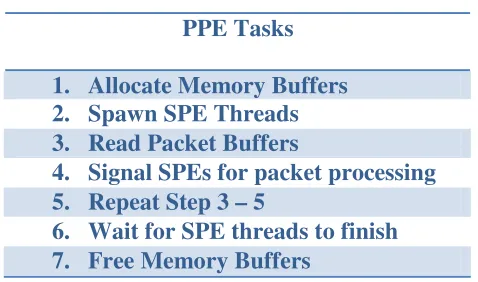
system was then free to exit safely. Table 1 below is a summary of the tasks performed
Table 1: Power Processing Element Tasks
PPE Tasks
1. Allocate Memory Buffers 2. Spawn SPE Threads 3. Read Packet Buffers
4. Signal SPEs for packet processing 5. Repeat Step 3 – 5
6. Wait for SPE threads to finish 7. Free Memory Buffers
4.1.2 Synergistic Processing Elements
The Synergistic Processing Elements (SPE) performed the calculations needed for
sessionization to occur. Their simple goal was to process packets as fast as possible with
as little delay as possible. The SPEs waited until packet buffers were ready, and then
processed each packet individually. Once a buffer of packets was completely processed,
a new buffer was received for processing until the entire system was stopped.
The SPEs started in a blocked state awaiting the signal for a buffer of packets.
Once the buffer of packets was received the SPE went through a series of steps. The first
step was to find how large the packet was. Once the packet length was determined, the
entire packet was copied into another buffer where it could be processed. The next step
was to compute a hash value to locate the session associated with the packet.
Once the associated session was found, the appropriate data session structure had
to be DMAed into the SPE from main memory. The data structure contained control
information such as how many packets were associated with the session, where the next
packet could be stored and the time from the last packet. The data structure is discussed
the session data structure was essential for retrieving, storing and aging sessions
appropriately.
Once the correct session structure was found, the packet pertaining to that session
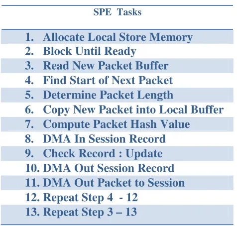
could be stored in the corresponding location. Table 2 is a summary the order of the
[image:36.612.188.426.228.455.2]tasks that needed to take place for the SPE to process packets related to various sessions.
Table 2: Synergistic Processing Element Tasks
SPE Tasks
1. Allocate Local Store Memory 2. Block Until Ready
3. Read New Packet Buffer 4. Find Start of Next Packet 5. Determine Packet Length
6. Copy New Packet into Local Buffer 7. Compute Packet Hash Value
8. DMA In Session Record 9. Check Record : Update 10.DMA Out Session Record 11.DMA Out Packet to Session 12.Repeat Step 4 - 12
13.Repeat Step 3 – 13
4.1.3 Session Data Structure
The session data structure (SDS) is one of the most important aspects of the
sessionization system. The SDS was used to keep track of the state of each session. The
SPE used this data structure to know where to store packets, when to age sessions, and
keep track of how many packets were in a session. It was found that that the SDS could
be stored in main memory or the SPE local store. Storing the SDS in main memory
some performance degradation compared to storing in local store. However, storing the
SDS in local store offered higher achievable bandwidths but could not scale with the
addition of more memory.
4.1.3.1
Structure Stored in Main Memory
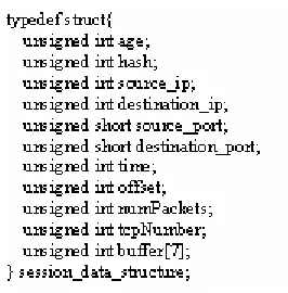
The session data structure was a 64-byte data structure that was read from main
memory into the SPE. The data structure was updated and then written back to main
memory after each packet was processed. The session data structure is shown in Figure 2
below.
Figure 2: Session Data Structure
When the Cell processor transfers data, it has to be aligned at 16-byte memory
locations; otherwise bus errors will occur. When data structures are multiples of 16-bytes
long then it makes DMA transfers easier to perform. The SDS maintained a structure
with 32 bytes of useful information and maintained another 32-bytes of unused space.
The unused buffer was maintained incase unforeseen session values were desired to be
kept track of that were not originally planned. Between the used and unused space the
The age attribute of the SDS is a value used by the sessionizer to know when a
session should or should not be aged. The details of this value are explained in more
detail in the session aging section. The other values were used as session identifiers as
well as current state of the number of packets.
The hash value acted as a sanity check to verify that the hash was indeed the
correct value for the particular session. Its primary purpose was to verify that the DMA
worked correctly, and that the correct session was being processed. The source IP,
destination IP, source port and destination port of a packet were used as unique identifiers
in a 4-tuple for determining the hash of a session.
The hash is an important part of the memory management scheme. All sessions
are stored and retrieved by the value of their hash. For simplicity, a simple hash function
was chosen that merely performed an XOR on the values of the 4-tuple. The 4-tuple was
stored to ensure that a session was the correct session and that it was not a hash collision,
which occurs when the IP source, IP destination, source port and destination port do not
match.
The time, offset and number of packets attributes were used to keep track of the
packets associated with the session. The time was logged for the first incoming packet.
If future packets were longer than the aging threshold then the session was aged. The
offset attribute was used to direct where the next packet should be stored in memory.
The number of packets kept track of how many packets were added to the current session.
The reason for storing the session data structure allowed for the SPE to process an
arbitrary number of sessions. The SPE could process as many sessions as memory
than 2-GB of main memory, more sessions could be addressed. For the case of the
PlayStation with 256-MB of main memory, session space was relatively limited.
An alternative to storing session data structures in main memory and transferring
them to local store was to allocate them directly in a SPE. The benefit of having the SDS
in the local store of the SPE meant that two DMA calls could be avoided which greatly
increased the achievable bandwidth. Instead of retrieving the SDS out of main memory
by DMA, waiting until it arrived, processing the structure and sending it back via DMA,
a simple check could be performed instead.
The downside of having the SDS in the local store is that the number of sessions
that could be tracked was limited to the space available in the SPE. As a reminder, the
SPE has only 256-KB of available memory for both instructions and data. Assuming that
128-KB of memory is free in the LS with a 64-B session data structure allows for only
2000 sessions to be tracked per SPE. In a system with 16 SPEs the maximum number of
sessions that can be tracked is then 32,000. The PlayStation scaled to 4 SPEs and was
capable of tracking 8144 sessions or 1024 sessions per SPE because slightly more than
128 KB was available. The performance of removing the DMAs associated with the SDS
had an impact and is discussed in detail in the results section.
4.1.3.2
TCP Modification
The Session Data Structure (SDS) could be modified slightly to account for
TCP/IP sequence information. A slight modification of the SDS involved adding the
packets are received out of order, it is then a trivial calculation to know where the next
[image:40.612.236.369.123.258.2]sequenced packet should go.
Figure 3: TCP Modified Session Data Structure
In addition to modifying the SDS, a slight modification was made in the way that
sessions were stored in main memory. The memory allocated in main memory was
changed to store pointers for the TCP data. This modification of pointer memory is
further discussed in the next section related to memory management.
The memory management scheme for the sessionizer was designed to store a
fixed number of sessions at any given time. This design greatly simplified the
complexity of storing sessions by pre-allocating all of the necessary memory for session
storage. In the future a dynamic system might be desirable, but for now a static baseline
is implemented.
The memory management scheme uses a very simple and straight forward hash
table. A hash table was used because its simplicity offered performance in speed.
Instead of dynamically allocating memory as packets came in, all memory was
pre-allocated. Memory was allocated as one large block, and within that block was divided
session memory that the user wanted to allocate per session as long as it fits within the
initial configured memory block.
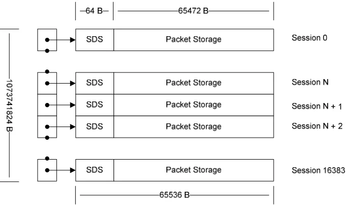
The following discussion is an example of a memory scheme that could be used
by a commercial implementation of the sessionizer with 64-KB session blocks and 1 GB
of free memory. The PS3 implementation actually used 16-KB session blocks with 256-
MB of free memory but for illustration purposes 1 GB will be used as an example. Using
this system configuration, one would be capable of tracking 16384 simultaneous sessions.
Again the number of sessions is solely limited by the amount of available memory in the
system. If more memory were available, then more sessions could be tracked. The
following diagram depicts how memory would be configured for session memory storage
[image:41.612.138.478.375.576.2]without a TCP modification.
Figure 4: Memory Aligned Sessions
In Figure 4, it can be seen that there are 16384 sessions, each with 64 KB of
allocated space. The entire memory is a full 1 GB with the SDS occupying the first 64 B
Transfer Unit (MTU) of a packet is 1500-B then a single session storage location could
store up to 43 packets for the same session if memory did not have to be aligned on 16
byte boundaries. The Cell requires that memory be stored on 16 B boundaries when
performing a DMA transfer. This requirement causes some space to be wasted if one just
DMAs to the next available memory location on a 16 B boundary.
As an example, in the case of having all 1500-B packets belonging to the same
session then only 42 packets can be stored in a memory location that could potentially
store 43. The reason for this difference is that there is wasted space between stored
packets. The following diagram illustrates how space is wasted in the scenario of
receiving all 1500-B packets. In Figure 5, it can be seen that each 1500-B packet is
actually occupying an extra 4-B so that the next packet can be aligned on a 16-B
boundary. In Figure 5, it can be seen that each 1500-B packet is actually occupying an
extra 4-B so that the next packet can be aligned on a 16-B boundary. Figure 6 shows the
memory allocation calculation.
[image:42.612.116.485.489.563.2]
Figure 6: Memory Allocation Example
In the case of packets that are naturally aligned at 16-B boundaries there is no
wasted space in memory. To eliminate wasted space one could fetch the 16 B of memory
into the SPE, and the new packet would be sent via DMA without a gap in memory.
However, this operation of fetching data to fill a memory gap one adds a delay to wait for
the memory. If one just DMAs memory to the next available offset, then one does not
encounter the penalty of waiting for a memory fetch. This sessionization implementation
was not concerned with wasting a few bytes of memory per DMA because it allowed for
faster processing rates by avoiding extra DMAs.
As previously stated, one could keep track of TCP order information if the
session structure were modified slightly. By adding a separate memory section after the
SDS that stored TCP information one could keep track of the order of incoming traffic.
This change is extremely beneficial for applications that need to scan packet data in
order. It also solves the problem of scanning packets across their packet boundary with
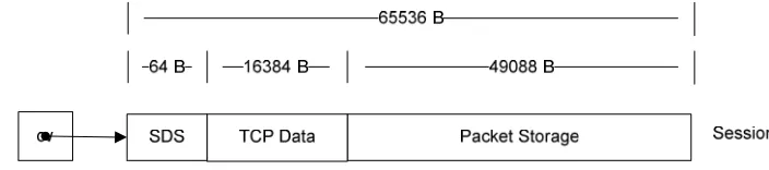
no break in the flow of information. Figure 7 depicts the TCP modification of a single
[image:43.612.83.435.598.676.2]session structure.
The modified session structure reduced the amount of packet storage and included
a 16-KB TCP Data section. The TCP Data section merely stored the 4-B TCP sequence
number of a packet and a 4-B offset of where the packet resided in the packet storage
memory location. Eight bytes of space were reserved for future work and to align the
TCP data DMAs on a 16 byte boundary. By keeping track of the first TCP sequence
number in the SDS then one knows where the next chronological packet belongs. For
instance, if the first packet sequence number is 100031 and packet 100033 arrives before
100032 then one can compute that it belongs in the second TCP Data Location. The
packet can be stored anywhere in the packet storage section, and it is referenced in the
TCP data section. This scheme allows one to create a DMA list that does a scatter/gather
and reorders the packets by following the offsets in the TCP section.
In the scenario where an average packet size is 48 bytes for a random TCP
session, one can keep track of 1023 TCP packets without any problem with the TCP data
section and packet storage sections. In most real life scenarios the average packet size
will be much larger than 48 bytes. In the extreme with 1500-byte packets, one could
keep track of 31 packets with the current configuration. Again, if there were more
memory then one would easily be able to scale the design and keep track of many more
packets.
4.1.4 Streaming Framework
The streaming framework is one of the most important parts of the entire system.
It is the mechanism for getting traffic into the Cell and processing the DMA calls for
aging scheme because DMA calls signaled when the sessions needed to be aged and
processed accordingly.
The streaming framework addressed the two processors on the cell. The first part
of the code focused on setting up the memory in the PPE and spawning threads
accordingly. The second part of the code focused on what the SPEs had to do. The PPE
was used as a controller to direct packets to the SPEs. The SPEs were kept in a wait
mode to accept traffic as it arrived and to process it as quickly as possible.
The PPE spawned individual threads for each SPE. The system was designed so
that the system could scale to any number of available SPEs and utilize any amount of
configured session memory. It was assumed that another system would perform a hash
on the packets before arriving to the system. The packets would be hashed and continue
into the Cell for processing. The hash is just a number that relates to any of the available
session structures in the memory scheme. Each SPE was assigned a range of hash values
that it could process. Each packet had its associated session hash and was sent to its
corresponding SPE for processing.
Upon receiving the packet, the SPE did a variety of checks to ensure that the SPE
was a packet that belonged to a session that it was tracking in memory. If the packet
belonged to a new session, then a new SDS had to be created. If the packet was part of a
session already being tracked then the SDS was retrieved via a DMA call from main
memory. The SDS was updated accordingly to register that a new packet was added.
The SDS was updated to specify where the next packet should go in the packet storage
space by updating the next packet offset location. The offset location was always aligned
Figure 8: Streaming Framework Flow
Figure 8 depicts the flow of the memory streaming framework. As the diagram
shows, the PPE is always pushing traffic to the SPEs. The SPEs are kept in a state that
continually processes packets as they arrive. The PPE buffers packets into 16-KB buffers
configuration is to minimize the amount of DMA requests. Instead of sending many
small DMAs, one large DMA is sent which mitigates the effects of an increase in latency.
It should be noted that in the 16-KB chunk, packets can be of any size. The algorithm
devised has no difficulty processing DMA packets of an arbitrary length. Since packets
with a maximum size of only 1500-bytes were allowed there was no problem of ever
having a packet that was larger than 16KB. If a packet were larger than 16KB, then
multiple DMAs would have to be used to store the packet, or a DMA list could be
created.
The streaming framework was implemented with two different packet buffering
schemes. The first scheme utilized a shared buffer synchronized among the SPEs. The
second scheme used multiple buffers distributed asynchronously to all the SPEs. The
packet buffers were always 16-KB in size, but how the SPEs received the buffers and the
synchronization used made a difference in how the system performed. It is documented
that 16-KB buffers are the most efficient and maximum size for transferring DMAs to the
SPEs which is why this size was chosen [7].
.
4.1.4.1
Synchronous Shared Buffer Streaming Model
The first buffer streaming model used a shared buffer that was synchronized to all
of the SPEs. The same 16-KB buffer was sent from the PPU to all of the other SPEs.
The buffer consisted of random packets that were processed by the SPE to which its hash
went down the list individually to process them. If the hash value did not match
something the SPE should process, then the packet was skipped.
Figure 9 depicts the shared buffer being used by all of the SPEs. Once an SPE
completed going through every packet in the list it signaled to the PPU that it had
completed the buffer. The PPU waited until the other SPEs also signaled they were done
with that buffer. Once all of the SPEs were done, the PPE signaled back to the SPEs to
[image:48.612.216.397.285.422.2]request the next shared buffer.
Figure 9: Shared Memory Buffer
4.1.4.2
Asynchronous Multi Distributed Buffer Streaming Model
The second streaming model used an asynchronous distributed multi buffer
model. This implementation was written to utilize the DMA engine more efficiently than
the shared memory model. Instead of using one 16-KB synchronized buffer across
multiple SPEs, many 16-KB asynchronous buffers were streamed instead. Once a SPE
finished a buffer it was ready to process the next available buffer. In addition, while the
SPE was operating on the current buffer, it was already requesting the next available. By
processing so that the SPE did not stall. Figure 10 depicts how the SPEs can have many
[image:49.612.217.397.149.300.2]more buffers available for processing.
Figure 10: Distributed Buffer Model
The shared memory model used random packets that mapped to multiple SPEs.
The main difference with the distributed model was to separate the mixing of packets
before they arrived to the Cell. By masking bit parameters of packets as they arrive, a pre
binning could occur to map that packet to an SPE buffer. Performing this simple
operation allows the SPEs to operate asynchronously of each other in a distributed
fashion. In the case of the testing implementation, it was assumed that this function of
pre-binning would occur on the host supplying traffic. It is a built in hardware
accelerated feature that most high performance interconnect cards have. In addition to
allowing SPEs to run asynchronously, it now allows the system to be scalable to multiple
nodes.
The method of pre-binning ensures that all sessions are delivered to the correct
system and the correct SPEs. The shared memory model does not allow the system to
got sent to one system and another packet from the same session were sent to another
system then the system fails. The system that performs pre-binning is nothing more than
another sessionizer that sits in front of the system with as many large bins as there are
SPEs. The bins correspond to the next chain of SPEs that will process the contents.
Achieving the desired rate for processing a link of traffic becomes merely a matter of
scaling the system to enough nodes.
4.1.5 Session Aging Scheme
Session aging was needed because there was a lack of memory on the Cell
processor for handling large numbers of session streams. If a new session arrived that
mapped to a preexisting hash of a session then the hash collision had to be handled with
accordingly. The session aging scheme was a means for ending sessions to make room
for new sessions.
If the Cell processor were equipped with an infinite amount of memory then one
would never need to age a session, and sessions could be stored forever. Since memory
is limited and session storage filled up quickly, memory had to be flushed clean to allow
for more sessions. This is just a product of the hash table mapping to multiple sessions
quickly. In the future when memory is more available for this architecture and other
similar ones that arise, aging will have to occur less.
There are a large variety of possible aging schemes. One could age on time,
storage requirements, packet information or a combination of all. For testing purposes
the aging scheme was kept very simple. If a session buffer collided with another mapped
If a session was already more than half full, and a new session collided with its
hash space, then the old session was aged, and the new session stored. If a new session
mapped to an old session space, and the storage was not full enough then that session was
dropped. A collision count was also kept on all session storage spaces for each new
session. If the session had many collisions but never aged, then it was aged because it
was using up space for too long. A session was always aged when its buffer became full.
If one wanted to age on time then it would not be a problem. A tick count of the
time could be kept for each session in the local store of the SPE. When a new buffer of
packets arrives into the SPE, the session expiration can be checked before processing and
aging. In addition, if a session has certain content in its header then it would also be very
possible to age a session. Looking for a fin flag in the TCP header to know a session is
complete is just one reason to age a session.
4.2. Testing
A UDP packet generator was created on the PPE of the Cell Processor for
simulating network traffic. The packet generator was configurable in the sense that it
could generate any number of sessions with any number of packets. It also had control
on forcing sessions to map to different hash locations to view the effects of aging. The
purpose of the testing environment was to ensure that packets were being stored properly.
The packet generator created an IPv4 compliant packet header with all the
necessary information for sending a packet. The payload of the generated packet could
with the contents of a continuous file, known character strings or random data with no
significance.
When stopping the sessionizing system, one had the option to view the contents of
all packet streams visually. This feature allows verification that all packets were being
aligned. A benefit of visually inspecting the storage memory was that any errors that
arose became apparent very quickly.
The system assumed that infiniband would be the main method for getting real
traffic onto the system. With this in mind, the packet generator stored packets into a
similar memory structure that infiband stacks implement. The SPEs read from this
memory location to simulate that traffic had arrived externally. In the future, using real
traffic should be as easy as referencing the correct memory locations and putting in the
correct signaling controls.
4.3. Chapter Summary
This chapter discussed the actual implementation of the PS3 based sessionization
system. The session data structures, shared vs. distributed streaming frameworks,
memory management, aging scheme and testing environment were discussed in detail.
An emphasis was placed on the two different streaming models. The shared streaming
model synchronized all SPEs to the same buffer for processing. In contrast, the
distributed streaming model allowed the SPEs to run asynchronously of each other so that
they were constantly fed packets. The testing environment utilized a combination of
random packets and simulated sessions with the ability to visually inspect sessions as
Chapter 5
Results and Discussion
The following chapter discuses the results of the PS3 implemented Cell based
network sessionizer. The network sessionizer was tested with a variety of simulated
traffic scenarios. The scenarios were used to gauge the maximum and minimum
performance that the system could achieve given various configurations. This chapter
discusses the worst, best and typical expected results achieved using the sessioner. This
section is broken into two parts that focus on the synchronous streaming framework
shared buffer implementation and the asynchronous distributed buffer method. The
results show that the shared buffer implementation does not scale while the distributed
buffer implementation is a more efficient design that does scale.
The system was tested with generated packets, and verified to work without any
problems. The system was set to run over time, iterating multiple times to push random
packets and have the system sessionize. The expected sessions processed, and packet
counts were always what were expected. The system handled variable length packets
without any problems. Upon visually inspecting the memory locations for select
sess