Int. J. Electrochem. Sci., 13 (2018) 8388 – 8395, doi: 10.20964/2018.09.54
International Journal of
ELECTROCHEMICAL
SCIENCE
www.electrochemsci.org
Short Communication
Pitaya-Like Carbon Nanofiber Sulfur Composites as Promising
Cathode Materials for High-Performance Li-S Batteries
Yanhua Wang1, Jianying Tong1, Kefeng Xie2,* 1
College of Biology and Environmental Engineering, Zhejiang Shuren University, Hangzhou 310000, China
2
State Key Laboratory of Plateau Ecology and Agriculture, Qinghai University, Xining 810016, China *
E-mail: [email protected]
Received: 5 June 2018 / Accepted: 11 July 2018 / Published: 5 August 2018
First, carbon nanofibers were prepared by electrospinning. Then, a CN/S composite was prepared by melting elemental sulfur via high-temperature heat treatment. Using the prepared CN/S composite as the cathode material, a lithium sulfur battery was made from the cathode material. The initial discharge capacity of the CN/S battery reached 1116 mAh g-1, the utilization ratio of sulfur was 73%, and the specific capacity was kept at 810 mAh g-1 after 100 cycles. The electrochemical performance of the CN/S composite was significantly higher than that of the elemental sulfur. It is shown that the lithium sulfur electricity can be effectively promoted by the CN/S composite.
Keywords: Carbon nanofiber, CN/S composite, cathode, Li-S battery.
1. INTRODUCTION
Elemental sulfur is abundant in the earth, inexpensive, environmentally friendly, non-toxic and has other advantages as a cathode material for lithium-sulfur batteries[1, 2]. The theoretical capacity of a lithium sulfur battery is 1675 mAh g-1, and the mass specific energy is 2600 Wh kg-1[3, 4, 5]. In recent decades, major breakthroughs in sulfur battery technology have been made, and the industrialization process is being pursued. However, the actual theoretical capacities of lithium sulfur batteries are still not sufficient. To solve the related technical problems, researchers have put considerable effort into the study of lithium-sulfur batteries. In particular, the mechanism of these batteries has been extensively studied. It is considered that the "shuttle effect" is an active substance, which is the main reason for the low utilization rate of sulfur and poor cycling stability[6].
improve the utilization of sulfur and the cycle stability of the batteries. The conductive carbon materials are mainly activated carbon[7], mesoporous carbon [8], and multi- walled carbon nanotubes [9, 10]. The conductive polymers mainly include polyaniline [11], polypyrrole [12], polythiophene [13]. Among these host materials for sulfur cathodes, some problems still exist in the cycle performance of as-prepared Li-S batteries[14, 15]. These problems exists because the host materials play a role in improving the conductivity of the whole composite cathode materials, but fail to inhibit the shuttle effect of polysulfide during the electrochemical process[16]. As a result, the best strategy to modify the performance of Li-S batteries is to improve the conductivity and restrain the polysulfide dissolution at the same time[17, 18].
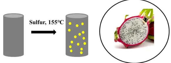
Thus, in the current study, carbon nanofiber (CN) with mesoporous structure and good conductivity was used as the host materials. The as-prepared CN/S composites exhibit pitaya-like structure (Figure 1). When the CN/S composites were applied as cathode materials, excellent electrochemical performance is obtained for lithium-sulfur batteries. The superior performance is attributed to the presence of CN, which could enhance the conductivity and restrain the polysulfide dissolution at the same time.
2. EXPERIMENTAL
2.1. Preparation of mesoporous carbon nanofiber (CN)
The mesoporous carbon nanofiber was prepared via electrospinning. A total of 1.4 g polyacrylonitrile and 0.8 g polystyrene were uniformly dissolved into a mixture of 10 ml DMF and 4 ml tetrahydrofuran. The mixture was then stirred for 0.5 h. Next, electrospinning was conducted at a voltage of 13 kV, with approximately 15 cm between the needle tip and the collector. The as-prepared polymer membrane was heated at 280 ℃ for 3 h in an N2 atmosphere. As a result, the CN was obtained.
2.2. Preparation of CN/S composite
The elemental sulfur and CN were mixed with a mass ratio of 2:1 and then fully lapped into a sealed tank and placed in a tube type atmosphere furnace with an argon gas to remove the air. The mixture was then heated up to 155 ℃ for 12 h in the flow argon atmosphere, and then warmed for 2 h at 300 ℃ at the same heating rate. After cooling, the CN/S composites were prepared by grinding for 1 h.
2.3. Materials Characterization
analyzer.
2.4. Electrochemical Measurements
The active material, acetylene black and polyvinylidene fluoride, are mixed uniformly according to a mass ratio of 8: 1: 1, and N- methyl -2- pyrrolidone is used as the solvent to make the positive electrode. It is evenly coated on the aluminum foil, dried at 60 ℃ for 24 h, and finally punched into a circular disc electrode with a diameter of 15 mm. The CR2016 battery is assembled in the glove box filled with argon using a metal lithium plate as the negative electrode., Ceglard 2400 membrane is used as the diaphragm and 1 mol/L LiTFSI/DME+DOL is used as the electrolyte. The CT2001A battery test system was used for a constant current charge discharge test at room temperature with a voltage of 1.5~3.0 V. Electrochemical impedance spectroscopy (EIS) was performed on a CHI660E electrochemical workstation. The frequency of the EIS test is 10-2~105 Hz. The AC amplitude for EIS is ±5 mV.
3. RESULTS AND DISCUSSION
Figure 1 shows the preparation process of the CN/S composite. As shown in Figure 1, after preparing carbon nanofiber, heat treatment was applied for obtaining CN/S composite at 155℃. Due to the mesoporous structure of CN, the sulfur dips into the interior of the carbon nanofiber, which exhibits a pitaya-like structure.
Figure 1. The schematic for the preparation of CN/S composites.
[image:3.596.151.442.486.594.2]
Figure 2. The nitrogen adsorption–desorption isotherms of CN and CN/S composite.
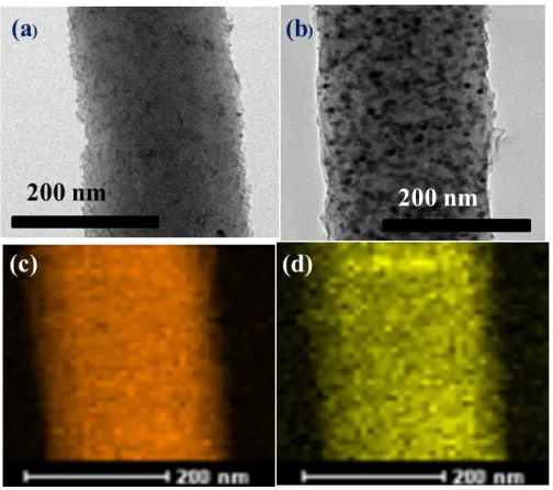
The TEM images of CN and CN/S composite are shown in Figure 3. From Figure 3a, it can be seen that the as-prepared CN exhibits a nanofiber structure. Its diameter is 160-180 nm. After sulfur impregnation, the CN/S composite shows pitaya-like structure, whose mesopores are filled with sulfur particles (Figure 3 b). Furthermore, the corresponding EDS is shown in Figure 3(c-d). It can be seen that the C and S element were uniformly dispersed in the whole CN/S composite.
Figure 3. The TEM images of (a) carbon nanofiber (CN), (b) CN/S composite, (c-d) corresponding elemental mapping of CN/S composite.
[image:4.596.172.424.370.593.2]
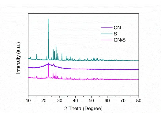
Figure 4. The XRD patterns of carbon nanofiber, sulfur and CN/S composite at 2 theta from 10° to 80°.
[image:5.596.167.430.87.272.2]Figure 5 shows the first charge-discharge profiles of sulfur and CN/S composite at the current density of 0.1 C. It can be seen that all of them have two discharge platforms near 2.3 V and 2 V. The initial discharge specific capacity of pure sulfur electrode is 806 mAh g-1. For the CN/S composite electrode, it exhibits initial discharge specific capacity of 1210 mAh g-1, which is much higher than the pure sulfur electrode. This high capacity is due to CN forming a good conductive network to increase the utilization of elemental sulfur[19], thus improving the specific capacity of lithium sulfur batteries.
Figure 5. The first charge-discharge profiles of pure sulfur and CN/S composite at the current density of 0.1 C between 1.5 V and 3.0 V.
[image:5.596.173.425.451.619.2]
elemental sulfur, which can ensure the transportation of ions and electrons in the electrode and improve the utilization of sulfur.
Figure 6. The cycle performance of pure sulfur and CN/S composite for 100 cycles at the current density of 0.2 C.
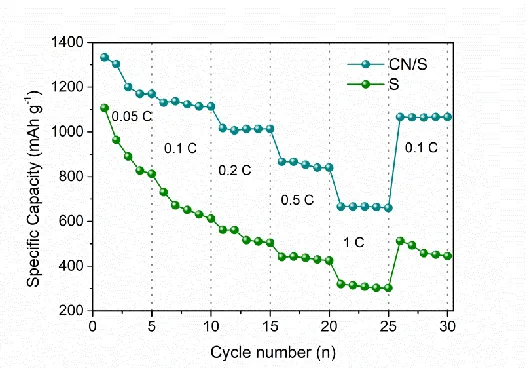
Figure 7 shows the rate performance of the pure sulfur electrode and the CN/S composite electrode at various current densities from 0.05 C to 1 C. The CN/S composite delivered high specific capacities of 1010 mAh g-1 and 916 mAh g-1, when the current density is 0.2 and 0.5 C. Even when the current density was improved to 1 C, the specific capacity still remained at 705 mAh g-1. For the pure sulfur electrode, the capacity faded rapidly with the increase of the current density. Consequently, it can be clearly seen that the CN/S composites could endure various current densities even at high current density of 1 C.
[image:6.596.170.425.125.302.2] [image:6.596.167.432.501.685.2]
In Figure 8, the EIS of the pure sulfur and CN/S composite is made up of a straight line and semicircle in the low-frequency region and the high-frequency region. The semicircle of the high frequency region represents the charge transfer resistance between the electrode and the solution interface, which is represented by the charge transfer impedance (Rct). The straight line of the low frequency region represents the related impedance of the diffusion of Li+ in the solid phase active substance. The Warburg impedance W is expressed as a description of the diffusion process[20, 21].
Figure 8. The EIS spectra of pure sulfur and CN/S composite.
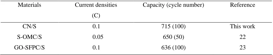
[image:7.596.166.433.189.376.2]Furthermore, to demonstrate the excellent electrochemical performance of the CN/S composite, the comparison of electrochemical performance for similar cathode materials is listed in Table 1. It can be seen that the CN/S composites exhibit stable cycle performance among these reported cathode materials for Li-S batteries.
Table 1. The comparison of kinds of cathode materials for Li-S batteries.
Materials Current densities
(C)
Capacity (cycle number) Reference
CN/S 0.1 715 (100) This work
S-OMC/S 0.05 650 (50) 22
GO-SFPC/S 0.1 636 (100) 23
4. CONCLUSIONS
[image:7.596.63.525.536.630.2]
initial discharge specific capacity of CN/S composite is 1210 mAh g-1 at a current density of 0.1 C. When the current rate is 0.2 C, the specific capacity of CN/S composite is 715 mAh g-1 after 100 cycles. Additionally, the CN/S composite shows an excellent rate performance at high current rates.
References
1. H. J. Zhao, N. P. Deng, J. Yan, W. M. Kang, J. G. Ju, Y. L. Ruan, X. Q. Wang, X. P. Zhuang, Q. X. Li and B. W. Chen, Chem. Eng. J., 347 (2018) 343.
2. Z. W. Ding, D. L. Zhang, R. R. Yao, C. Li, X. W. Cheng and T. Hu, Int. J. Hydrogen Energ., 43 (2018) 10502.
3. T. G. Jeong, Y. S. Lee, B. W. Cho, Y. T. Kim, H. G. Jung and K. Y. Chung, J. Alloy Compd., 742 (2018) 868.
4. W. C. Ren, W. Ma, S. F. Zhang and B. T. Tang, Chem. Eng. J., 341 (2018) 441.
5. C. H. Tsao, C. H. Hsu, J. D. Zhou, C. W. Chin, P. L. Kuo and C. H. Chang, Electrochim. Acta, 276 (2018) 111.
6. Z. Li, B. Y. Guan, J. T. Zhang, X. W. Lou, Joule, 1 (2017) 576.
7. A. Song, Y. Huang, X. P. Zhong, H. J. Cao, B. Liu, Y. H. Lin, M. S. Wang and X. Li, J. Membrane Sci., 556 (2018) 203.
8. S. K. Liu, X. B. Hong, D. Q. Wang, Y. J. Li, J. Xu, C. M. Zheng and K. Xie, Electrochim. Acta, 279 (2018) 10.
9. Y. Liu, A. K. Haridas, Y. K. Lee, K. K. Cho and J. H. Ahn, Appl. Suf. Sci., 3 (2018) 21. 10.H. Zhang, P. J. Zuo, J. F. Hua, Y. L. Ma, C. Y. Du, X. Q. Cheng, Y. Z. Gao and G. P. Ying,
Electrochim. Acta, 238 (2017) 257.
11.J. H. Xu, B. Jin, H. Li and Q. Jiang, Int. J. Hydrogen Energ, 42 (2017) 20749.
12.G. S. Jiang, F. Xu, S. H. Yang, J. P. Wu, B. Q. Wei and H. Q. Wang, J. Power Sources, 395 (2018) 77.
13.Z. B. Xiao, L. Y. Li, Y. J. Tang, Z. B. Cheng, H. Pan, D. X. Tian and R. H. Wang, Energ. Storage Mater., 12 (2018) 252.
14.Y. L. An, Y. Tian, H. F. Fei, G. F. Zeng, H. W. Duan, S. C. Zhang, P. Zhou, L. J. Ci and J. K. Feng, Mater. Lett., 228 (2018) 175.
15.W. Y. Li, Y. Pang, T. C. Zhu, Y. G. Wang Y. Y. Xia, Solid State Ionics, 318 (2018) 82.
16.S. K. Liu, X. B. Hong, D. Q. Wang, Y. J. Li, J. Xu, C. M. Zheng and K. Xie, Electrochim. Acta, 279 (2018) 10.
17.H. J. Yang, A. Naveed, Q. Y. Li, C. Guo, J. H. Chen, J. Y. Lei, J. Yang and J. L. Wang, Energ. Storage Mater., 15 (2018) 299.
18.Z. Li, B. Y. Guan, J. T. Zhang and X. W. Lou, Joule, 1 (2017) 576.
19. N. Akhtar, H. Y. Shao, F. Ai, Y. P. Guan, Q. F. Feng, H. Zhang, W. K. Wang and Y. Q. Huang, Electrochim. Acta, 282 (2018) 758.
20. J. Li, X. Zhang, J. Q. Guo and R. F. Peng, Ionics, 22 (2016) 2307.
21. N. Li, X. He, K. H. Chen, S. Y. Chen and F. Y. Gan, Mater. Lett., 15 (2018) 156.
22. Z. W. Ding, D. L. Zhao, R. R. Yao, C. Li, X. W. Cheng and T. Hu, Int. J. Hydrogen Energ., 43 (2018) 10502.
23. H. L. Wu, L. Xia, J. Ren, Q. J. Zheng, F. Y. Xie, W. J. Jie, C. G. Xu and D. M. Lin, Electrochim. Acta, 278 (2018) 83.