Anderson, Pamela and Macdonald, Malcolm (2012) Static highly elliptical
orbits using hybrid low-thrust propulsion. In: 22nd AAS/AIAA Spaceflight
Mechanics Meeting, 2012-01-29 - 2012-02-02. ,
This version is available at https://strathprints.strath.ac.uk/36806/
Strathprints is designed to allow users to access the research output of the University of Strathclyde. Unless otherwise explicitly stated on the manuscript, Copyright © and Moral Rights for the papers on this site are retained by the individual authors and/or other copyright owners. Please check the manuscript for details of any other licences that may have been applied. You may not engage in further distribution of the material for any profitmaking activities or any commercial gain. You may freely distribute both the url (https://strathprints.strath.ac.uk/) and the content of this paper for research or private study, educational, or not-for-profit purposes without prior permission or charge.
STATIC HIGHLY ELLIPTICAL ORBITS USING HYBRID
LOW-THRUST PROPULSION
Pamela Anderson,
*Dr Malcolm Macdonald,
†The use of extended static-highly elliptical orbits, termed Taranis orbits, is considered for continuous observation of high latitude regions. Low-thrust propulsion is used to alter the critical inclination of Molniya-like orbits to any inclination required to optimally fulfill the mission objectives. This paper investigates a constellation of spacecraft at 90deg inclination for observation of latitudes beyond 55deg and 50deg, considering: spatial resolution, radiation environment, number of spacecraft and End of Life debris mitigation measures. A constellation of four spacecraft on a 16-hr Taranis orbit is identified to enable continuous observation to 55deg latitude. Neglecting constraints to minimize the radiation allows the number of spacecraft in the constellation to be reduced to three on a 12-hr orbit. Similarly to view continuously to 50deg, eight spacecraft on a 16-hr orbit are required; this is reduced to five neglecting radiation constraints. It is anticipated that it is significantly more cost effective to reduce the number of required launches and employ additional radiation shielding. Thus, a constellation of three or five spacecraft on the 12-hr Taranis orbit is considered the most beneficial when observing to latitudes of 55deg and 50deg
respectively. Hybrid solar sail / Solar Electric Propulsion systems are considered to enable the Taranis orbits, where the acceleration required is made up partly by the acceleration produced by the solar sail and the remainder supplied by the electric thruster. Order of magnitude mission lifetimes are determined, a strawman mass budget is also developed for two system constraints, firstly spacecraft launch mass is fixed, and secondly the maximum thrust of the thruster is constrained. Fixing mass results in negligible increases in mission lifetimes for all hybrid cases considered, solar sails also require significant technology development. Fixing maximum thrust of the electric thruster increases mission lifetime and solar sails are considered near to mid-term technologies. This distinction highlights an important contribution to the field, illustrating that the addition of a solar sail to an electric propulsion craft can have negligible benefit when mass is the primary system constraint. Technology requirements are also outlined, including sizing of solar arrays, electric thruters, propellant tanks and solar sails.
*
[email protected], PhD Candidate, Advanced Space Concepts Laboratory, University of Strathclyde, Glasgow, Scotland, E.U.
†
[email protected], or [email protected], Associate Director, Advanced Space Concepts Laboratory, University of Strathclyde, Glasgow, Scotland, E.U.
INTRODUCTION
In recent years, there has been significant interest in building a comprehensive Arctic observing system to accurately track environmental and climate processes in this region [1]. The rapidly changing environment of the Arctic is of high meteorological significance, as the weather has an impact on global climate predictions. Deriving high quality climate records in high latitude regions requires a data refresh rate of 15 minutes as is typically required for so-called continuous meteorological observations.
Currently, imaging of high latitude regions is conducted using composite images from spacecraft in Geostationary (GEO) and Low-Earth Orbits (LEOs) [2]. However, the oblique viewing geometry from Geostationary systems to latitudes above around 55deg [3] and the short orbital period of spacecraft in LEO means there is currently no source of continuous imagery for the Polar Regions obtained with sufficiently high refresh rate. The spatial discontinuity and lack of adequate temporal resolution severely affects many applications.
Alternatively, Highly Elliptical Orbits (HEOs) are being considered for observation of Polar Regions to allow continuous observation of the Earth. One such example is the Molniya orbit, which has a period around one half of a sidereal day and has a ‘critical inclination’ of 63.43deg. At this inclination, the orbit experiences no drift in argument of perigee due to the oblateness of the Earth. Although the Molniya orbit offers an alternative for Polar imaging, the fixed critical inclination means continuous hemispherical imaging to the same quality as geostationary systems, in the regions not covered by GEO, is not possible. This gap in information for Polar Regions means new solutions are being sought. Consequently this paper evaluates the use of extended HEOs for improved high latitude Earth Observation (EO).
The extension of HEOs using continuous low-thrust propulsion to counteract the perturbations due to the Earth’s gravity have previously been considered, to enable HEOs with free selection of the ‘critical inclination’ [4], with no rotation of the apsidal line [5-7]. Such orbit extensions are termed Taranis orbits [7]. One particular example is a Taranis orbit inclined at 90deg to the equator to enable continuous observation of frigid and neighboring temperate regions.
Previously, Taranis orbits have been considered using Solar Electric Propulsion (SEP), a mature technology with a high Technology Readiness Level (TRL) [8, 9] and low Advanced Degree of Difficulty (AD2) [8, 9]. However, mission lifetimes are limited by the amount of propellant that can be carried. Consequently, consideration is given to the addition of a solar sail to the system. Hybrid SEP / solar sail systems reduce the propellant requirements of the SEP thruster, while the SEP system compensates for the inability of the solar sail to thrust in the direction of the Sun. The use of a small solar sail on the spacecraft also contributes towards lowering the AD2 of solar sailing [8].
This paper for the first time, considers the design of a HEO constellation for spacecraft on 90deg
inclination Taranis orbits, firstly for observation to 55deg latitude, where observations from GEO begin to degrade. Thus this is the minimum requirement of the constellation to complete the Global Observing System [1]. Secondly, observation to 50deg latitude is considered to provide a more significant overlap in data from geostationary platforms. In determining the most beneficial constellation, the spacecraft environment, spatial resolution, number of spacecraft and End of Life (EoL) debris mitigation measures will be considered. Following identification of the HEO constellation the addition of a solar sail to the system is considered to enable the Taranis orbits using a hybrid low-thrust propulsion system. Two cases are considered assuming different constraining parameters. Firstly, it is assumed that the launch mass of the spacecraft is fixed. Thus, the mass of the solar sail is limited to be no greater than the mass of propellant saved by the addition of the sail. Secondly, consideration is given to a system limited by the maximum thrust of the SEP system, thus allowing the initial mass of the spacecraft to vary. This additional mass is used in part to add the solar sail, and partly to increase the useful payload capacity. The impact of the added solar sail is considered on mission lifetime along with the development of Strawman mass budgets to quantify the benefit, if any, of a hybrid SEP / solar sail system over a pure SEP system.
HEO CONSTELLATION
Constraints for Selecting a HEO Constellation
The key requirements for selecting the most beneficial orbit are as follows:
In order to complete the Global Observing System [1] and allow continuous observation of the Earth at any time, the HEO constellation is required to provide continuous imaging of the region above 55deg
latitude. As this is where observations from geostationary spacecraft begin to degrade, this is the minimum requirement of the constellation. However to provide a significant overlap in data from GEO, a constellation which images continuously to 50deg latitude is also considered.
R2. The minimum Observational Zenith Angles (OZAs) are 27deg and 33deg when viewing to latitudes of 55deg and 50deg respectively.
In order to ensure imaging of equal quality to that produced by geostationary platforms, the OZA of the defined latitude limit, when viewed from GEO is calculated, and is then used as the OZA for the Taranis orbits [7]. Considering, a geostationary orbit at an altitude of 36,000km results in minimum elevation angles of 27deg and 33deg, or OZAs of 63deg and 57deg, viewing to latitudes of 55deg and 50deg
respectively. Employing these minimum elevation angles for the Taranis orbits ensures that these provide at the very least data of equal quality to that produced by geostationary systems when viewing the same location.
R3. The apogee altitude of the orbit will be less than 45,000km.
In order to ensure adequate spatial resolution with current imaging platforms the limit placed on the apogee altitude is selected as 25% higher than GEO altitude and is the limit currently being used for HEO missions, including the Canadian Polar Communication and Weather (PCW) mission [10, 11].
R4. The mission will comply with debris mitigation guidelines.
The increasing volume of debris in orbit around the Earth has recently seen debris mitigation guidelines implemented. These identify two protected regions, the first covering LEO zones up to altitudes of around
2,000km and around geostationary altitude bands extending 200km above and below 35,678km as well as plus and minus 15deg in latitude. Thus at the EoL, spacecraft should be removed from these regions, either to a parking orbit, which requires perigee altitude to be > 2,000km [12], or de-orbited within 25 years, which requires perigee altitude < 600km [12].
Although the following is not a strict requirement, it is a condition which should be considered when selecting the orbit for the constellation:
• The semi-latus rectum altitude should be > 15,000km to avoid the region of high energy protons.
One downside to these, highly elliptical, Molniya-like orbits is the potentially hazardous radiation environment, caused by the spacecraft crossing the Van Allen Radiation Belts twice per orbit. During this time the spacecraft experiences radiation effects from both electrons and protons, however, the main threat to on board micro-electronics and solar cells comes from high-energy protons [13]. Thus, in order to minimize the effects from radiation, the spacecraft should avoid the region containing high-energy protons, with energy E > 10MeV. The altitude distribution of proton flux in the equatorial plane is plotted inFig. 1, to show the regions in space where the peak density of high-energy protons occur. The radiation environment encountered by spacecraft on the orbits considered in this paper has been determined using ESAs online Space Environment Information System (SPENVIS)*. Trapped proton and electron environments shown in this paper are modeled using NASA models AP-8 [14] and AE-8 [15] respectively, where the proton environment is modeled at solar minimum conditions and the electron environment is modeled at solar maximum conditions. This is the standard stated by ESA to give the most conservative analysis of the radiation environment [16].
*
Fig. 1. Example of vertical profile of trapped proton spectrum in the equatorial plane.
It can be seen that the proton flux for high-energy protons (>10MeV) falls to below 10 particles per cm2 per second at an altitude of 15,000km. Therefore, to avoid a high density of highly energetic protons, and reduce the risk of damage to the spacecraft, the semi-latus rectum altitude should be above 15,000km.
Altitude Limit
The limit placed on apogee altitude is converted into a valid region of values for the semi-major axis,
(1 ) 45, 000
a E
H =a +e −R < km (1) Eq. (1) can expressed in terms of orbital period and eccentricity and plotted to give the region for the possible orbits with apogee altitudes below 45,000km.
Debris Mitigation
In determining the HEO constellation, debris mitigation measures are included with the aim of expending the least amount of propellant at the spacecraft EoL. As perigee altitudes between 600km and
2,000km require a maneuver to either re-orbit or de-orbit the spacecraft, the selected orbit should be above
2,000km or below 600km to avoid expending propellant while complying with debris mitigation guidelines.
Radiation Environment
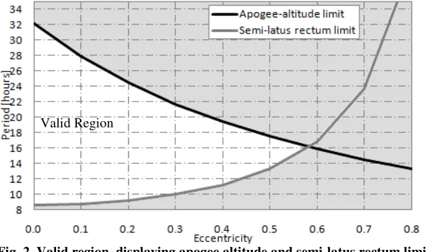
The limit placed on the semi-latus rectum altitude, is given as,
2
(1 ) 15, 000 E
p=a −e > km R+ (2)
[image:5.595.166.456.94.257.2]As with Eq. (1) the semi-latus rectum limit can be expressed in terms of the orbital period and eccentricity. This is plotted alongside the apogee altitude limit, shown in Fig. 2, to give the valid region for the orbits.
Fig. 2. Valid region, displaying apogee altitude and semi-latus rectum limit.
Fig. 2 shows that the possible eccentricity for the low radiation orbit is limited to between 0 and 0.55.
1.E-01 1.E+00 1.E+01 1.E+02 1.E+03 1.E+04 1.E+05 1.E+06 1.E+07 1.E+08
0 10,000 20,000 30,000 40,000 50,000
P
ro
to
n
F
lu
x
[
cm
-2s -1]
Alitude [km]
E > 1MeV E > 2MeV E > 5MeV E > 10MeV
[image:5.595.151.455.505.685.2]Observation to 55deg
[image:6.595.152.462.155.334.2]Within the valid region shown in Fig. 2 combinations of perigee and apogee altitudes are considered. Visibility analysis is conducted to determine the number of spacecraft required to provide continuous observation of the region above 55deg latitude, employing an OZA of 27deg to ensure imaging of equal quality to that produced by geostationary systems, the results are given in Fig. 3.
Fig. 3. Observation to 55deg showing apogee-altitude and semi-latus rectum limits.
From Fig. 2, the most beneficial orbit occurs at the point closest to the intersection of the apogee altitude and semi-latus rectum limit lines. At this point, the orbit period is shown to be around 16.6 hours (from Fig. 3), however, in order to provide an integer number of revolutions in an integer number of sidereal days, such that the ground-track repeats in a relatively short time, the orbit period is reduced to 16 hours. The most suitable perigee altitude for the 16-hr orbit is then selected to minimize both the number of spacecraft and radiation dose.
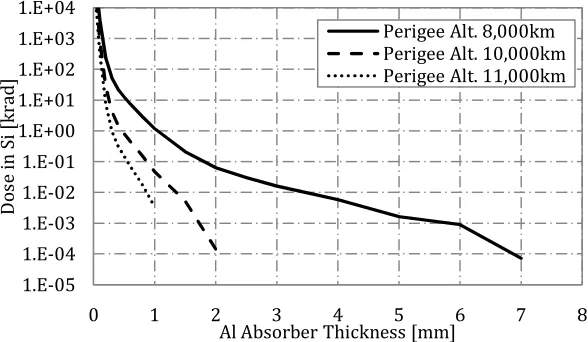
As the perigee altitude increases, the radiation dose from high-energy protons decreases, this is illustrated in Fig. 4.
Fig. 4. Comparison of trapped proton dose for 16-hr Taranis orbits of varying perigee altitudes,
for mission durations of 5 years.
It is shown that the total proton flux for the 16-hr orbit with a perigee altitude of 8,000km is almost completely absorbed after approximately 7mm of aluminum shielding; this is compared with only 2mm for a perigee altitude of 10,000km. However, as perigee altitude increases, eccentricity decreases and the time above high-latitude regions decreases, these orbits may therefore require a greater number of spacecraft to provide continuous observation. The orbit parameters for the 16-hr Taranis orbits, the required number of
1.E-05 1.E-04 1.E-03 1.E-02 1.E-01 1.E+00 1.E+01 1.E+02 1.E+03 1.E+04
0 1 2 3 4 5 6 7 8
D
o
se
i
n
S
i
[k
ra
d
]
Al Absorber Thickness [mm]
Perigee Alt. 8,000km Perigee Alt. 10,000km Perigee Alt. 11,000km
[image:6.595.157.451.443.614.2]spacecraft and the acceleration required to achieve these orbits are detailed in Table 1. The method for determining the required acceleration has been derived previously in [7].
Table 1. Comparison of 16-hr Taranis orbits of varying perigee altitudes.
Perigee Altitude 8,000km
Perigee Altitude 10,000km
Perigee Altitude 11,000km
Apogee Altitude 43,740km 41,740km 40,740km
Eccentricity 0.5543 0.4922 0.4612
Required Acceleration 0.0113mm/s2 0.00814mm/s2 0.00697mm/s2
No. Spacecraft 4 4 5
Four spacecraft are shown to be necessary to give continuous observation for perigee altitudes between
8,000km and 10,000km, thus since the radiation dose from high-energy protons decreases with perigee altitude, a perigee altitude of 10,000km is more beneficial. Although, increasing the perigee altitude to
11,000km further reduces the radiation dose, the number of required spacecraft is seen to increase from four to five. Consequently, a 16-hr Taranis orbit with a perigee altitude of 10,000km and apogee altitude of
41,740km is selected as the most favorable for high latitude observation, when minimizing both the number of spacecraft and the radiation dose.
From Fig. 3 it is shown that taking into consideration the radiation experienced by the spacecraft, a minimum of four spacecraft are necessary to provide continuous observation to 55deg. Investigation is therefore conducted to determine to what extent the perigee altitude needs to be lowered to provide the same level of coverage using only three spacecraft. Although reducing the perigee altitude will significantly increase the radiation dose from high-energy protons, it is anticipated that it may be more cost efficient to employ additional radiation shielding if the number of spacecraft can be reduced. Furthermore, launching to an altitude of 10,000km would be both difficult and costly.
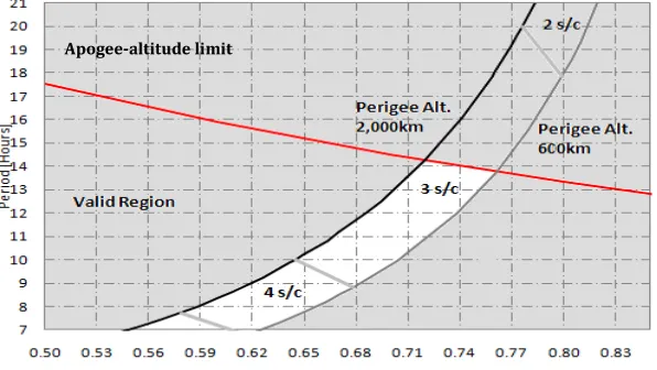
Visibility analysis is once again conducted to 55deg neglecting the restrictions to minimize radiation to determine the number of spacecraft required in this case. As explained previously, to avoid performing an orbital maneuver at the EoL, to ensure debris mitigation measures are met, the perigee altitude should ideally be selected as below 600km or above 2,000km. However, the lower perigee altitude is below 600km, the more pronounced the effects of atmospheric drag, thus the more ∆υ required to maintain the orbit throughout its life. Thus, the perigee altitude of the 16-hr Taranis orbit should either be selected as 600km
or 2,000km; where the total acceleration required from the low-thrust propulsion system to enable these orbits is 0.0864mm/s2 and 0.0564mm/s2 respectively. Visibility analysis giving the number of spacecraft for orbits with perigee altitudes of 600km and 2,000km are shown in Fig. 5.
Fig. 5. Observation to 55deg, showing apogee altitude limit and required number of spacecraft.
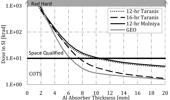
No longer including the constraints to minimize the effects of radiation reduces the required number of spacecraft to give continuous observation to 55deg to three. For example, considering a 12-hr orbit, a constellation of three spacecraft can provide continuous coverage above 55deg latitude. The perigee altitude in this instance is selected as 2,000km as at an altitude of 600km propellantis required to maintain the orbit, which will degrade over time due to the effects of atmospheric drag. The Total Ionizing Dose for
[image:7.595.160.458.460.628.2]the 12-hr Taranis orbit is shown in Fig. 6. For comparison, the Total Ionizing Dose for the 16-hr orbit, a conventional Molniya orbit and a GEO are also shown.
Fig. 6. Total Ionizing Dose for various orbits with mission durations of 5 years.
Fig. 6 shows that for typical aluminum absorber thicknesses, between 2mm and 4mm, it is necessary that the platforms for the 12-hr Taranis orbit use space qualified hardware. However, the values of radiation are below those requiring radiation hard materials. It is also shown for this level of shielding; the Total Ionizing Dose experienced by the 12-hr Taranis orbit is comparable to that experienced by geostationary platforms. It is shown in Fig. 6 that geostationary platforms also require space qualified parts, and as this system is proposed to complement the constellation of geostationary spacecraft this is not expected to be a significant issue. The additional cost required to launch to the 16-hr, lower radiation, orbit and the extra spacecraft required is expected to be significantly more than employing additional shielding and launching to a substantially lower perigee altitude.
Observation to 50deg
Observations from GEO begin to degrade at around 55deg latitude; the previous analysis therefore details the minimum requirements to provide continuous global observation at any time. Therefore, to provide a more substantial overlap in data, the visibility analysis is repeated viewing to 50deg latitude; using a OZA of 33deg. Including both the apogee altitude requirement and semi-latus rectum limit to minimize the radiation effects a minimum of seven spacecraft are required, with eight spacecraft necessary on the 16-hr orbit with perigee altitude of 10,000km. Once again neglecting the conditions to minimize radiation, the number of spacecraft is reduced to five on a 12-hr orbit. The significant increase in cost associated with launching three additional spacecraft to considerably higher perigee altitudes means the 12-hr orbit with a perigee altitude of 2,000km and apogee altitude of 38,470km is the orbit considered in the remainder of the paper.
HYBRID SEP / SOLAR SAIL PROPULSION
Considering, a hybrid solar sail / SEP system to enable the selected Taranis orbit, the total acceleration required to maintain the 12-hr orbit with perigee altitude of 2,000km is 0.0564mm/s2. Using hybrid propulsion a fraction of this acceleration is generated by the solar sail with the SEP system supplying the remainder of the acceleration. The total required acceleration is given by,
tot s p
a =a +a (3)
where, as is the acceleration generated by a perfectly reflecting solar sail [17]
2 2 ( . )ˆ
s
Gm r
β
=
s
a r n n (4)
1.E+00 1.E+01 1.E+02 1.E+03
0 2 4 6 8 10 12 14 16 18 20
D
o
se
i
n
S
I
[k
ra
d
]
Al Absorber Thickness [mm]
12-hr Taranis 16-hr Taranis 12-hr Molniya GEO
COTS
and where, β is the dimensionless sail lightness number defined in [17]. One solar sail design parameter is the solar sail characteristic acceleration, which is defined as the actual acceleration experienced by the sail at a solar distance of 1 AU with the sail surface normal to the Sun, and may be written as [17],
2
( / )
s sc
s sc s
P a m A η σ = + (5)
At a distance of 1AU from the Sun the magnitude of the solar radiation pressure, P, exerted on a perfectly absorbing surface is 4.56 x 10⁻⁶ N/m2 [17]. The solar sail efficiency,η, is a function of the optical properties of the sail film and the sail shape, and accounts for the finite reflectivity of the film; typically this taken to be of the order of 0.85-0.9 [17]. Eq. (5) shows that the sail characteristic acceleration is a function of the spacecraft mass, msc, excluding the solar sail mass. The mass of the spacecraft will decrease
as the SEP thruster consumes propellant. Thus, the sail characteristic acceleration increases over time.
LOCALLY OPTIMAL CONTROL LAWS
Locally optimal control laws are used to maximize the instantaneous rate of change of a given orbital element and provide the required thrust orientation in analytical form [18]. These locally optimal control laws are used only by the solar sail component of the force, whereas the SEP system uses the simple switching law previously derived [7]. The argument of perigee locally optimal control law is derived from the argument of perigee variational equation, given in terms of classical orbital elements in Eq.(6),
[
]
d
R T N
d ω
ω λ
θ = (6)
where,
(
)
1 cot p cos e p r sin p e r isin p ω θ λ θ θ ω − = + − + (7)The locally optimal control law thus requires the solar sail thrust to be maximized along λω, [18]. The
solar sail trajectory is planet-centered; therefore λωmust be transposed into the Sun-sail line reference
frame, using standard transformation matrices. The transformation is performed in two stages; first, transformation from planet-centered RTN to Earth-centered inertial using the inverse of the transformation matrix given in Eq. (8) [19],
(
)
(
)
(
)
(
)
(
)
(
)
(
)
(
)
(
)
(
)
cos cos cos cos sin sin RTN ECI ECIO T O
cos cos sin isin cos sin sin icos sin sini
sin cos cos isin sin sin cos icos cos sini O
isin icos cosi
ω θ ω θ ω θ ω θ ω θ
ω θ ω θ ω θ ω θ ω θ
=
+ Ω − + Ω + Ω + + Ω +
= − + Ω − + Ω − + Ω + + Ω +
Ω − Ω
(8)
The second stage is to transform from Earth-centered inertial to Sun-line coordinates, using the inverse of the transformation matrix given in Eq.(9) [19]. It is noted that it is assumed the co-ordinate systems are orthogonal and that parallax effects are negligible.
[ ]
0
SUN ECI ECI
cos sin cos sin sin O T O sin cos cos cos sin O
sin cos
ϑ ϑ ε ϑ ε
ϑ ϑ ε ϑ ε
ε ε = = − − (9)
With conversion of λω into the Sun-sail line coordinate system, the pitch angle of the ideal force vector is
given as,
( )
ˆarccos xss
where,λˆ / λ /λ / λ ˆ ˆ ˆ
z
ss ss ss ss ss ss
x y ω x y z
ω =λω ω λω ω λ ω =λω λω λω . The sail orientation to maximize the sail
thrust vector is found, the locally optimal sail pitch angle is given from [20],
( )
( )
2 2
3 9 8
tan
4
cos cos sin sin
α α α
α
α
− + +
= (11)
The locally optimal sail clock angle is given as,
ˆ
ˆ
2 2
ˆ
arccos
z
z
y λ δ
λ λ
=
+
(12)
The solar sail thrust vector in Eq. (4) is found using Eq.(13) [17] cos
sin sin
sin cos
α
α δ
α δ
=
n (13)
As the sail is in an Earth-centered trajectory the normal vector orientation given in Eq. (13) must be transformed into planet-centered RTN coordinates. This is again performed in two stages transforming from Sun-line coordinates to Earth-centered inertial, using the inverse of the transformation matrix given in Eq.(9), and from Earth-centered inertial to Earth-centered RTN, using the matrix in Eq.(8).
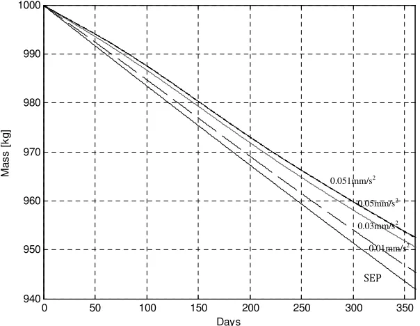
[image:10.595.148.450.386.620.2]Using the defined solar sail equations, various solar sail characteristic accelerations are considered to determine the sail characteristic acceleration that offers the most benefit in terms of the lowest acceleration demand on the SEP system. As the characteristic acceleration of the sail is increased, at some point the acceleration provided by the solar sail will be so high that the SEP system will be required to counteract the sail acceleration, rather than supplement it. Using a spacecraft with an initial mass of 1000kg and considering four values of solar sail characteristic accelerations of 0.01, 0.03, 0.05, and 0.051mm/s2, the mass of the spacecraft are shown in Fig. 7 over the first year of operation.
Fig. 7. Fuel consumption of spacecraft on 12-hr Taranis orbit over first year using various solar sail characteristic accelerations.
It is seen from Fig. 7 that, as expected, each solar sail considered offers some benefit over the SEP only cases, by decreasing the amount of propellant consumed, thus increasing the final spacecraft mass. The solar sail with a characteristic acceleration of 0.05mm/s2 offers the highest reduction in fuel consumption. This turning point was determined by a process of trial and error, increasing the characteristic acceleration in increments of 0.001 mm/s2. Increasing the characteristic acceleration above this value causes the SEP
0 50 100 150 200 250 300 350
940 950 960 970 980 990 1000
Days
M
a
s
s
[
k
g
]
0.01mm/s2
SEP
0.03mm/s2
0.05mm/s2
system to counteract the accele the SEP system. This turning po sail acceleration increases, as in hr orbit, given by a sail char accelerations of 0.01mm/s2 and and 8.8kg respectively.
The acceleration provided rotational axis with respect to throughout the year, the necessa
Fig. 8. SE
It is shown that from Apri demand on the SEP system occ is shown throughout the Northe
MISSION ANALYSIS
Mission Lifetime
By evaluating the performa mission lifetimes of the orbit f determined using Eq. (14). In t given by taking the average acc
Table 2 Aver
Characteristic Acc
SE
It is noted from Table 2 tha sail characteristic acceleration, of the cosine of the pitch angle particular mass fraction and spe for the SEP only system and for
0.040 0.042 0.044 0.046 0.048 0.050 0.052 0.054 0.056 0.058 1 A v e ra g e S E P A cc e le ra ti o n [ m m / s 2]
eleration generated by the solar sail, thus increasing th point will, however, move as the SEP system uses up p in Eq.(5). The maximum propellant mass saving over th aracteristic acceleration of 0.05mm/s2 is around 11kg
nd 0.03mm/s2 offering reductions in propellant consum
d by the solar sail varies throughout the year due to to the orbit plane, thus the acceleration required by t ssary SEP acceleration is shown in Fig. 8.
SEP acceleration required for 12-hr orbit over one y
pril to August the acceleration from the sail decrease ccurs during this time. A significant decrease in the requ hern Hemisphere winter.
ance of the 12-hr Taranis orbit in terms of propellant t facilitated by means of SEP only and hybrid SEP / n the hybrid SEP / solar sail systems the constant acce cceleration required by the SEP system over the first yea
0
0
ln f sp
f
p
m I g L t
m a
= = −
erage SEP acceleration over a 12 month period.
cceleration [mm/s2] Average SEP acceleration [mm
SEP only 0.0564
0.01 0.0534
0.03 0.0491
0.05 0.0476
0.051 0.0477
that the acceleration required from the SEP system dec n, this is due to the useful sail acceleration magnitude b gle. The lifetime of the 90deg, 12-hr Taranis orbit, is th specific impulse. The resulting possible mission lifetim for each of the hybrid propulsion systems considered.
2 3 4 5 6 7 8 9 10 11
Months SEP only asc=0.01mm/s^2 asc=0.03mm/s^2 asc=0.05mm/s^2 asc=0.051mm/s^2 SEP asc=0.01mm/s2 asc=0.03mm/s2 asc=0.05mm/s2 asc=0.051mm/s2
the fuel consumption of propellant and the solar the first year for the
12-1kg. With characteristic mption of around 3.5kg
o the tilt of the Earth’s the SEP system varies
year.
ses, thus the maximum equired SEP acceleration
t consumption, possible solar sail systems are celeration in Eq. (14) is
ear, given in Table 2.
(14)
m/s2]
ecreases by less that the being set by the square thus determinable for a mes are shown in Fig. 9
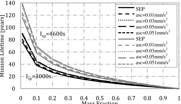
Fig. 9. Taranis mission lifetime for SEP only and various solar sail characteristic accelerations.
Fig. 9 shows the possible mission lifetimes for the Taranis orbit as a function of mass fraction for two values of specific impulse of 3000s and 4600s, using SEP and hybrid SEP / solar sail systems with various solar sail characteristic accelerations. For example, using a mass fraction of 0.5 the resulting mission lifetime for each system for each of the specific impulse values is given inTable 3.
Table 3 Mission lifetime.
Characteristic Acceleration [mm/s2] Isp=3000s
Lifetime [years]
Isp=4600s
Lifetime [years]
SEP only 11.5 17.6
0.01 12.1 18.6
0.03 13.2 20.2
0.05 13.6 20.8
[image:12.595.135.462.331.404.2]0.051 13.6 20.8
Table 3 shows that employing a solar sail with a characteristic acceleration of 0.05mm/s2 can enable a mission just over two years longer than a Taranis orbit enabled using a pure SEP system, with a specific impulse of 3000s. It is also shown that an increase in lifetime of over three years is possible increasing the specific impulse to 4600s. This highlights the benefit of the hybrid solar sail / SEP system due to the reduced propellant consumption from the SEP only system. It is noted that this is a conservative analysis, as the sail will become more effective as the SEP propellant is depleted and hence the mission lifetimes will in fact be longer than detailed here.
Initial Spacecraft Mass
The maximum allowable initial mass of the spacecraft is determined for the given thrust shown in Fig. 10.
Fig. 10. Maximum allowable initial mass for the 12-hr Taranis orbit.
0 20 40 60 80 100 120 140
0 0.1 0.2 0.3 0.4 0.5 0.6 0.7 0.8 0.9 1
M
is
si
o
n
L
if
e
ti
m
e
[
y
e
a
rs
]
Mass Fraction
SEP
asc=0.01mm/s^2 asc=0.03mm/s^2 asc=0.05mm/s^2 asc=0.051mm/s^2 SEP
asc=0.01mm/s^2 asc=0.03mm/s^2 asc=0.05mm/s^2 asc=0.051mm/s^2
Isp=4600s
Isp=3000s
SEP
asc=0.01mm/s2 asc=0.03mm/s2 asc=0.05mm/s2 asc=0.051mm/s2
SEP
asc=0.01mm/s2 asc=0.03mm/s2
asc=0.05mm/s2 asc=0.051mm/s2
[image:12.595.159.452.517.685.2]It is apparent from Fig. 10 that two factors can constrain the system; firstly, where the launch mass of the spacecraft is fixed and secondly where the maximum thrust of the SEP system constrains the mission.
Fixed Launch Mass
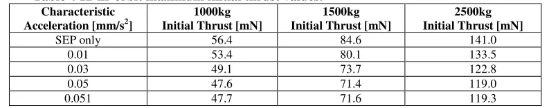
[image:13.595.99.502.170.248.2]Firstly, the case where the launch mass of the spacecraft is fixed is considered. Selecting three initial masses of spacecraft of 1000kg, 1500kg and 2500kg the corresponding required initial thrust values are given in Table 4.
Table 4 12-hr orbit maximum initial thrust values.
Characteristic Acceleration [mm/s2]
1000kg Initial Thrust [mN]
1500kg Initial Thrust [mN]
2500kg Initial Thrust [mN]
SEP only 56.4 84.6 141.0
0.01 53.4 80.1 133.5
0.03 49.1 73.7 122.8
0.05 47.6 71.4 119.0
0.051 47.7 71.6 119.3
It can be seen that for a particular initial mass of spacecraft, the addition of a solar sail reduces the thrust required by the SEP system. A maximum reduction in thrust of 22mN occurs for the 2500kg
spacecraft with a characteristic acceleration of 0.05mm/s2. Note that the additional mass incurred by adding a solar sail remains constrained by the fixed launch mass. As such, the solar sail mass is constrained to be no more than the saving in propellant mass for a given mission lifetime.
Fixed Maximum Thrust
The second case considers the maximum thrust of the SEP system as the constraining parameter. The maximum allowable initial mass of the spacecraft for a particular thrust value is found usingFig. 10, with the allowable mass shown to increase for each of the hybrid systems considered. For example, fixing the available SEP thrust at three particular values of 94mN, 150mN, and 210mN corresponding to the thrust available from NASA’s Solar Electric Propulsion Technology Application Readiness (NSTAR) thruster [21], the qualified thrust of the QinietiQ T6 thruster, and the maximum thrust of the QinetiQ T6 thruster [22] respectively, results in the maximum allowable mass values given in Table 5.
Table 5 12-hr orbit maximum allowable mass values.
Characteristic Acceleration [mm/s2]
94mN Initial Mass [kg]
150mN Initial Mass [kg]
210mN Initial Mass [kg]
SEP only 1667 2660 3723
0.01 1760 2809 3933
0.03 1914 3055 4277
0.05 1975 3151 4412
0.051 1971 3145 4403
It is shown that the addition of solar sails can offer a significant increase in the allowable mass of the spacecraft. The maximum allowable mass is given using a solar sail of 0.05mm/s2 with considerable increases in mass of around 308kg, 491kg, and 689kg for each available thrust. This additional mass is used to add an advanced light-weight solar sail to the system, providing the same characteristic acceleration and to allow additional SEP propellant useful payload to be carried.
Mass Budget
Although the mission lifetime analysis characterizes possible mission lifetimes of the Taranis mission in terms of propellant consumption, it should also be investigated whether these conditions allow a useful payload to be carried using a realistic solar sail. The initial mass of the spacecraft is composed of many elements, detailed in [23]. The total mass of the onboard systems, msys, including data processing,
telecommunications, guidance, navigation and control, structural mass, and any power system requirements beyond the SEP system requirements are assumed to total 500kg. The mass of the SEP thruster, mSEP, is
found as a function of the maximum power provided by the system, and is given by,
SEP SEP max
m =k P (15)
With the specific performance of the thruster given as kSEP = 0.02 kg/W [24]. The mass of the spacecraft
power system required to provide electrical energy to the SEP system is given by,
P SA max
[image:13.595.97.496.407.482.2]Using a conservative estimate of the specific performance of the solar array, from [25], of kSA = 1
/45
kg/W. The mass of the propellant is found as a function of the mission duration, and is given by Eq.(17),
max
0 prop
SP
T
m
t
I g
=
∆
(17)The mass of the propellant tanks, mtank, is a function of the mass of the propellant, mtank=0.1 mprop. The
mass of the subsystems is calculated and the remaining mass gives the payload capacity.
Fixed Launch Mass
[image:14.595.170.431.235.293.2]The maximum solar sail masses that can be added to the spacecraft, for the fixed launch mass case, are determined from the amount of propellant saved through the use of a hybrid low-thrust propulsion system (Fig. 7). The propellant mass saving per year in orbit for the three given solar sail characteristic accelerations are given in Table 6.
Table 6 12-hr orbit propellant mass saving over the first year.
Characteristic Acceleration [mm/s2] Mass Saving [kg]
0.01 3.495
0.03 8.755
0.05 10.770
0.051 10.767
The maximum mass of the solar sail is thus given by the propellant mass saving per year multiplied by the lifetime of the mission. In this instance, the mission lifetimes used to size the solar sails are given by the SEP only case. Where, mission lifetimes are 6.77 years, 9.27 years, and 11.28 years for the 1000kg,
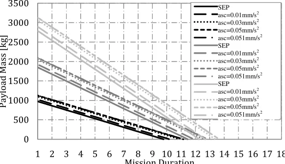
[image:14.595.157.451.362.535.2]1500kg, and 2500kg spacecraft respectively. Using Eqs.(15) - (17), the payload mass is plotted as a function of mission lifetime.
Fig. 11. Payload mass as a function of mission lifetime - fixed launch mass 12-hr orbit.
Fig. 11 allows the maximum mission lifetime to be determined, that is, where there is no longer any capacity for useful payload. The maximum mission lifetimes for each initial spacecraft mass, for each of the solar sail characteristic accelerations considered are given in Table 7.
Table 7 Maximum mission lifetimes - fixed launch mass, 12-hr orbit.
Characteristic Acceleration [mm/s2] 1000kg 1500kg 2500kg
SEP only 6.77 9.27 11.28
0.01 6.81 9.48 11.70
0.03 6.86 9.82 12.38
0.05 6.86 9.94 12.64
0.051 6.84 9.91 12.61
A modest increase in the Taranis mission lifetime is shown with the addition of a solar sail to the system, with the maximum increase in lifetime of just over oneyear, occurring for the 2500kg spacecraft with a solar sail characteristic acceleration of 0.05mm/s2. Table 7 shows that for the 1000kg and 1500kg
0 200 400 600 800 1000 1200 1400 1600 1800
1 2 3 4 5 6 7 8 9 10 11 12 13 14 15 16 17
P
a
y
lo
a
d
M
a
ss
[
k
g
]
Mission Duration [years]
SEP
asc=0.01mm/s^2 asc=0.03mm/s^2 asc=0.05mm/s^2 asc=0.051mm/s^2 SEP
asc=0.01mm/s^2 asc=0.03mm/s^2 asc=0.05mm/s^2 asc=0.051mm/s^2 SEP
asc=0.01mm/s^2 asc=0.03mm/s^2 asc=0.05mm/s^2 asc=0.051mm/s^2
SEP
asc=0.01mm/s2
asc=0.03mm/s2
asc=0.05mm/s2
asc=0.051mm/s2
SEP
asc=0.01mm/s2
asc=0.03mm/s2
asc=0.05mm/s2
asc=0.051mm/s2
SEP
asc=0.01mm/s2
asc=0.03mm/s2
asc=0.05mm/s2
[image:14.595.100.498.587.662.2]spacecraft the increases in mission lifetime produced by the addition of the solar sail are negligible, with all increases less than a year for all solar sails. Thus, it is shown from Table 7 and Eq.(5), that in order to make any significant increase in the lifetime of the Taranis mission, a large light solar sail is required, thus, it is expected that considerable development in solar sail technology is required.
Fixed Maximum Thrust
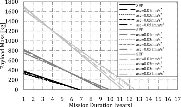
[image:15.595.158.449.224.392.2]As constraining the mass of the spacecraft allows very little increase in the lifetime of the Taranis missions without significant development of the solar sails, the scenario where the maximum thrust of the SEP system is the constraining parameter is now considered. Solar sail masses in this case are assumed to equal half of the additional mass and the remaining half of the mass is used to increase the capacity for useful payload. The resulting payload masses for each system are given in Fig. 12.
Fig. 12. Payload mass as a function of mission lifetime - fixed initial thrust, 12-hr orbit.
[image:15.595.140.454.437.507.2]The increase in the mission lifetime for each of the hybrid solar sail / SEP systems considered for each of the initial thrust values is shown in Fig. 12. The maximum mission lifetimes are given in Table 8.
Table 8 Maximum mission lifetimes - fixed initial thrust, 12-hr orbit.
Characteristic Acceleration [mm/s2] 94mN 150mN 210mN
SEP only 9.77 11.46 12.27
0.01 10.19 11.88 12.69
0.03 10.89 12.57 13.38
0.05 11.15 12.84 13.66
0.051 11.14 12.83 13.64
Table 8 shows that although the maximum increase in mission lifetime is approximately the same as the fixed launch mass case, more significant increases are shown for the smaller initial thrusts and for solar sails with smaller characteristic accelerations. In addition to the greater increase in mission lifetime, the solar sails required to achieve this increase are notably heavier and are thus more feasible solutions. Solar sails in the fixed launch mass case range between around 24kg and 121kg, and in the fixed thrust case range from around 47 kg to 340 kg.
Thrust Range Analysis
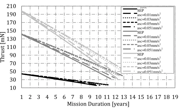
Although the Taranis orbits require constant acceleration, in reality as the propellant is consumed the mass of the spacecraft decreases, thus causing an increase in the acceleration from the SEP system. A variable thrust SEP system is therefore required. The thrust range necessary from the SEP system can be determined by finding the thrust at the beginning of the mission with all the propellant, and the thrust at the end of the mission with zero propellant. These thrust ranges are shown for a range of mission lifetimes for each of the hybrid systems and the SEP only case for both the fixed launch mass case, for each orbit, in Fig. 13, and the fixed maximum SEP thrust case in Fig. 14.
0 500 1000 1500 2000 2500 3000 3500
1 2 3 4 5 6 7 8 9 10 11 12 13 14 15 16 17 18
P
a
y
lo
a
d
M
a
ss
[
k
g
]
Mission Duration
SEP
asc=0.01mm/s^2 asc=0.03mm/s^2 asc=0.05mm/s^2 asc=0.051mm/s^2 SEP
asc=0.01mm/s^2 asc=0.03mm/s^2 asc=0.05mm/s^2 asc=0.051mm/s^2 SEP
asc=0.01mm/s^2 asc=0.03mm/s^2 asc=0.05mm/s^2 asc=0.051mm/s^2
SEP
asc=0.01mm/s2
asc=0.03mm/s2
asc=0.05mm/s2
asc=0.051mm/s2
SEP
asc=0.01mm/s2
asc=0.03mm/s2
asc=0.05mm/s2
asc=0.051mm/s2
SEP
asc=0.01mm/s2
asc=0.03mm/s2
asc=0.05mm/s2
Fixed Launch Mass
Fig. 13. Thrust ranges required by SEP system - fixed launch mass.
In Fig. 13 it is shown that the addition of a solar sail to the SEP system decreases the thrust range required by the SEP system. For example, considering the 1500kg initial thrust for a 4 year mission the SEP only system requires 82.9mN at the beginning of the mission and 62.5mN at the end of the mission. This is compared with 71.4mN at the beginning of the mission and 55.9mN at the end of the four years for the solar sail of characteristic acceleration 0.05mm/s2.
Fixed Maximum Thrust
Fig. 14. Thrust ranges required by SEP system - fixed maximum thrust.
Fig. 14 shows that, as in the fixed launch mass case, as larger solar sails are added to the system, the required SEP thrust range decreases. Considering the spacecraft with an initial thrust of 210mN and mission duration of 5 years, the SEP only case has a final thrust of 141mN. This is compared with final thrusts of
146mN, 151mN, 153mN, and 152mN respectively for each of the given solar sail characteristic accelerations.
Technology Requirements
Given that the parameters of the Taranis platform are defined for the mass and power required the systems and technology requirements of the platform can be investigated. Firstly, the requirements of the spacecraft including SEP thrusters, solar arrays and propellant tanks are discussed, followed by investigation of the possible solar sail design for each case discussed.
25 45 65 85 105 125
1 2 3 4 5 6 7 8 9 10 11 12 13 14 15 16 17
T h ru st [ m N ]
Mission Duration [years] SEP asc=0.01mm/s^2 asc=0.03mm/s^2 asc=0.05mm/s^2 asc=0.051mm/s^2 SEP asc=0.01mm/s^2 asc=0.03mm/s^2 asc=0.05mm/s^2 asc=0.051mm/s^2 SEP asc=0.01mm/s^2 asc=0.03mm/s^2 asc=0.05mm/s^2 asc=0.051mm/s^2 10 30 50 70 90 110 130 150 170 190 210
1 2 3 4 5 6 7 8 9 10 11 12 13 14 15 16 17 18 19
T h ru st [ m N ]
[image:16.595.150.445.364.543.2]SEP Thrusters
Assuming the total acceleration is constituted by two thrusters at any given time, one for each of the radial and transverse directions, the approximate required range per thruster for various mission durations, for the SEP only case and the hybrid solar sail / SEP systems, are stated in Table 9 - Table 10 for the
1000kg and 2500kg spacecraft.
[image:17.595.94.506.154.280.2]Fixed Launch Mass
Table 9 Maximum and minimum thrust per thruster, 1000kg initial mass.
[image:17.595.147.451.457.568.2]Duration [years]
SEP
Max [mN] SEP Min [mN] 0.01mm/s2 Max [mN] 0.01mm/s2 Min [mN] 0.03mm/s2 Max [mN] 0.03mm/s2 Min [mN] 0.05mm/s2 Max [mN] 0.05mm/s2 Min [mN]
4 28 21 27 20 25 19 24 19
6 28 17 27 17 25 16 24 16
Table 10 Maximum and minimum thrust per thruster, 2500kg initial mass.
Duration [years]
SEP
Max [mN] SEP Min [mN] 0.01mm/s2 Max [mN] 0.01mm/s2 Min [mN] 0.03mm/s2 Max [mN] 0.03mm/s2 Min [mN] 0.05mm/s2 Max [mN] 0.05mm/s2 Min [mN]
6 70 43 67 42 61 40 60 40
8 70 33 67 33 61 33 60 33
10 70 23 67 24 61 26 60 26
Table 9 and Table 10 demonstrate the reduction in thrust range required by the SEP thrusters for all of the hybrid systems proposed for each thruster. With the thrust range decreasing as the solar sail characteristic acceleration increases. All of the thrust ranges shown are achievable using current technology. The NSTAR thruster, which has undergone significant ground testing in addition to a flight test on the Deep Space 1 (DS1) spacecraft [21], is capable of providing between 20mN and 94mN of thrust. Thus, four NSTAR thrusters, one per required direction, are capable of providing the thrust range required for the 2500kg initial mass, for all duration of mission considered. Four thrusters are also capable of providing the required thrust range for the 1000kg spacecraft for the 4 year mission for both the SEP only case and the hybrid case using a solar sail with a characteristic acceleration of 0.01mm/s2. The QinetiQ T6 thruster, is throttelable between 30mN and 210mN [22] four thrusters are therfore capable of providing the required thrust range for all of the mission durations for an initial mass of 2500kg.
Fixed Maximum Thrust
Again, assuming the total acceleration is constituted by two thrusters at any given time, one for each of the radial and transverse directions, the approximate required range per thruster are stated in Table 11 - Table 12 for the 94mN and 210mN initial thrusts.
Table 11 Maximum and minimum thrust per thruster, 94mN.
Duration [years] Max Thrust [mN] SEP Min [mN] 0.01mm/s2 Min [mN] 0.03mm/s2 Min [mN] 0.05mm/s2 Min [mN]
4 47 35 35 36 37
8 47 22 23 25 26
Table 12 Maximum and minimum thrust per thruster, 210mN.
Duration [years] Max Thrust [mN] SEP Min [mN] 0.01mm/s2 Min [mN] 0.03mm/s2 Min [mN] 0.05mm/s2 Min [mN]
4 105 78 79 81 82
6 105 63 66 69 70
10 105 34 38 44 46
Table 11 and Table 12 again demonstrate the reduction in thrust range required by the SEP thrusters for all of the hybrid systems proposed. It is shown that four NSTAR thrusters, one per required direction, are capable of providing the thrust range required for all initial thrust systems, for all duration of mission considered, for both SEP only and hybrid systems. Four QinetiQ T6 thrusters are also capable of providing the required thrust range for all of the systems for all mission lifetimes for an initial thrust of 210mN, and for 4 and 8 year missions for an initial thrust of 94mN.
Solar Arrays
Fixed Initial Mass
The power required by each spacecraft of different initial mass values, the mass of the solar arrays (from Eq.((16)) and the required solar array area, found using the Solar flux of 1370W/m2 at 1 AU, are given in Table 13 - Table 14 for the fixed launch mass case for the SEP only case and the hybrid case with a solar sail characteristic acceleration of 0.05mm/s2 and in Table 14 for the fixed maximum electric thrust.
Table 13 Solar array sizing, SEP only.
Initial Mass [kg] Max Power [kW] Solar Array Mass [kg] Solar Array Area [m2]
1000 1.2 26 4
1500 1.8 40 5
2500 3.0 66 9
Table 14 Solar array sizing, asc = 0.05mm/s2.
Initial Mass [kg] Max Power [kW] Solar Array Mass [kg] Solar Array Area [m2]
1000 1 22 3
1500 1.5 33 4
2500 2.5 56 7
Table 13 and Table 14 show the modest reduction in both mass and required area of the solar arrays by the use of hybrid solar sail / SEP system, with the required area decreasing as the solar sail characteristic acceleration is increased. Results show that the required sizes of the solar arrays, for all cases, are modest and feasible using current solar array technology. With the solar arrays of Rosetta totaling 61.5m2 [26] and SMART-1’s arrays having an area of 10m2 [27] for spacecraft of 3000kg and 370kg respectively.
Fixed Maximum Thrust
Table 15 Solar array sizing, 12-hr orbit - fixed maximum thrust.
Initial Thrust [mN] Max Power [kW] Solar Array Mass [kg] Solar Array Area [m2]
94 2.0 44 6
150 3.2 70 9
210 4.4 88 13
Table 15 shows that, as with the fixed launch mass case, the required sizes of the solar arrays, for all cases, are feasible using current solar array technology.
Propellant Tanks
Finally, the storage requirements for the requisite propellant mass for given mission durations are examined. The propellant mass for each system considered are determined using Eq. (17) and are shown in Table 16 for the fixed launch mass cases and in Table 17 for the fixed initial thrust.
Table 16 Propellant mass for 12-hr orbit - fixed launch mass.
Initial Mass [kg]
Mission Duration
[years]
SEP only Propellant Mass
[kg]
asc=0.01mm/s2
Propellant Mass [kg]
asc=0.03mm/s2
Propellant Mass [kg]
asc=0.05mm/s2
Propellant Mass [kg]
asc=0.051mm/s2
Propellant Mass [kg]
1000 4 242 229 211 204 205
1500 7 635 601 553 536 537
2500 9 1360 1288 1184 1148 1360
Table 16 shows the reduced propellant mass for the hybrid solar sail / SEP systems. The NASA Dawn mission Xenon tanks have a capacity of 425kg of propellant, thus the Taranis spacecraft (both SEP only and hybrid systems), propellant mass requirements can be accommodated using a single propellant tank for a four year mission. For a seven year mission this is increased to two tanks for all proposed systems. Finally, three tanks are required for nine year missions using solar sails with characteristic accelerations of
0.03mm/s2 and 0.05mm/s2, this is increased to four for the SEP only case and using solar sails with characteristic accelerations of 0.01mm/s2and 0.051mm/s2. The single tank volume is 0.27m3, so that the equivalent tank radius for a spherical tank is 0.4m, thus the total propellant mass requirements for the possible Taranis platforms can be accommodated in a modest volume. Note that results are included for the
0.051mm/s2 solar sail are included to show the increase in propellant mass from the 0.05mm/s2sail.
Table 17 Propellant mass for the 12-hr orbit - fixed maximum thrust.
Initial Thrust [mN] Mission Duration [years] Propellant Mass [kg]
94 4 403
150 7 1126
Table 17 shows that the propellant mass requirements can be accommodated using a single propellant tank for a four year mission and, three propellant tanks for the seven year mission and finally five tanks for the seven year missions.
Solar Sail
Sizing of the solar sail is conducted to determine the technology development, if any, needed to allow the proposed hybrid low-thrust propulsion missions to become feasible.
Fixed Launch Mass
[image:19.595.157.459.214.388.2]The design space for each of the solar sails for an initial mass of 1000kg is shown in Fig. 15. This gives the required area, found using Eq.(5) for each sail of a given characteristic acceleration, varying the sail loading and assuming a sail efficiency of 0.85 [17].
Fig. 15. Design space for various characteristic accelerations – fixed initial mass.
Fig. 15 shows the design space for each of the solar sails considered, where below the line the total spacecraft mass is below the initial mass value, and is thus the design limit of the sail. Similar figures can also be plotted for the initial mass values of 1500kg and 2500kg, although these are not included within the paper. However, these figures show an increase in solar sail area and a significant decrease in sail loading as the initial spacecraft mass increases. Thus, significant development in solar sail technology is required to produce larger, lighter sails to make these hybrid solar sail / SEP systems feasible.
The case where the initial thrust is fixed, the solar sails are equal to half of the additional mass gained by the addition of the sail. Plotting similar figures to Fig. 15 for each initial thrust value it is shown that although solar sail areas are of the same order of magnitude as the fixed launch mass case, the solar sails are heavier and are thus more near term solutions.
CONCLUSION
A constellation of spacecraft on extended, static-highly elliptical orbits have been identified. These orbits use low-thrust propulsion to modify the critical inclination of the orbits to 90deg to enable continuous observation of areas above 55deg and 50deg latitudes. The most beneficial orbit has been identified as a 12-hr orbit with perigee altitude of 2,000km and apogee altitude of 38,470km. Three spacecraft are required on this orbit to provide continuous observation to 55deg, which increases to five for observation to 50deg. Spacecraft on this orbit require space qualified components, although the total ionizing radiation dose experienced by the spacecraft is not high enough to require radiation hardened materials. The Total Ionizing Dose is also comparable to that experienced by geostationary platforms. It is anticipated to be significantly less costly to launch three spacecraft to the lower perigee orbit, than launch an additional spacecraft to a lower radiation orbit with a considerably higher perigee altitude.
Hybrid solar sail and solar electric propulsion systems have been considered to maintain this novel orbit, termed a Taranis orbit. This hybrid propulsion lowers the demand on the solar electric propulsion system by reducing the amount of propellant consumed, which may in turn increase the possible lifetime of the mission and the capacity for useful payload. Two constraining parameters were considered, firstly the
asc=0.01mm/s2
asc=0.03mm/s2
asc=0.05mm/s2
case where the launch mass of the spacecraft is fixed, and secondly where the maximum thrust of the solar electric propulsion thruster constrains the system. Where, the launch mass of the spacecraft is fixed, the increase in the mission lifetime from the pure electric propulsion system is negligible. The solar sails required to achieve any significant increase in lifetime are extremely large, light sails, and thus, considerable developments in solar sail technology are necessary to make these missions feasible. In the case of the fixed maximum electric thrust, the increase in mission lifetime is greater than that achieved using a fixed launch mass. In addition to this, the physical size of the solar sails required are of the same order of magnitude as the fixed launch mass sails, however, these are much heavier sails making them more feasible solutions. It has therefore been shown that the gain from the addition of a solar sail to the system is very little, unless the mass of the spacecraft is increased.
NOTATION
a semi-major axis
ap solar electric propulsion constant
acceleration
as solar sail acceleration
As solar sail area
asc solar sail characteristic
acceleration
atot total solar sail and solar electric
propulsion acceleration
e eccentricity
i inclination
G universal gravitational constant
g0 gravity of Earth
Ha apogee altitude
Isp specific impulse
ksa specific performance of solar array
ksep specific performance of thruster
L mission lifetime
mf final mass
mo initial mass
mp mass of power system
mprop propellant mass
ms solar sail mass
msc mass of spacecraft excluding solar
sail
msep solar electric propulsion thruster
mass
mtank propellant tank mass
n solar sail thrust vector
N normal acceleration
p semi-latus rectum
P solar radiation pressure
Pmax maximum power
r orbital radius
R radial acceleration
RE mean radius of Earth
T transverse acceleration
Tmax maximum thrust
tf mission duration
α locally optimal sail angle
pitch angle for ideal force vector β solar sail lightness number δ locally optimal sail clock angle ηs solar sail efficiency
ϑ angle measured from the first point of Aries to the planet
θ true anomaly
λω rate of change of argument of
perigee
σs solar sail loading parameter
ω argument of perigee ascending node angle
SI Units used throughout unless otherwise stated.
REFERENCES
1. "WMO vision for the GOS in 2025.." Port of Spain, Trinidad and Tobago, 2009.
2. Lazzara, M. A., Stearns, C. R., Staude, J. A., and Knuth, S. L. "10 Years of Antarctic Composite Images," 7th Conference on Polar Meteorology and Oceanography and Joint Symposium on High-Latitude Climate Variations. Proceedings. Boston, Ma, American Meteorological Society, Hyannis, MA, 2003.
3. Pieri, D. C. "Virtual Polar Geostationary Satellite: A trade Study for the NASA Earth Science Technology Office."
4. Wertz, J. R., “Mission Geometry: Orbit and Constellation Design and Management”, The Space Technology Library, ed., Vol., 2001. p. 619.
5. Anderson, P., and Macdonald, M. "Extension of Earth Orbits Using Low-Thrust Propulsion," 61st International Astronautical Congress. Prague, Czech Republic, 2010.
6. Anderson, P., and Macdonald, M. "Extension of the Molniya Orbit Using Low-Thrust Propulsion,"21st AAS/AIAA Spaceflight Mechanics Meeting,New Orleans, LA,2011
7. Anderson, P., and Macdonald, M. "Extension of Highly Elliptical Earth Orbits using Continuous Low-Thrust Propulsion," Journal Guidance Control and Dynamics, 2011, Accepted November 2011
8. Macdonald, M., and McInnes, C. R. "Solar Sail Science Mission Applications and Advancement,"
Advances in Space Research Vol. In Press, 2011,
9. Macdonald, M., “Solar Sailing: Applications and Technology Advancement”, ed. Hall, J., Vol., InTech, 2011. p.
10. Trishchenko, A., and Garand, L. "Spatial and Temporal Sampling of Polar Regions from Two-Satellite System on Molniya Orbit," Journal of Atmospheric and Oceanic Technology, 2011, 11. Trishchenko, A., and Garand, L. "Three Apogee 16-h Highly Elliptical Orbit As Optimal Choice
For Continuous Meteorological Imaging Of Polar Regions," Journal of Atmospheric and Oceanic Technology, 2011,
12. Janovsky, R., Kassebom, M., Lubberstedt, H., and Romberg, O. "End-Of-Life De-Orbiting Strategies For Satellites," 2002,
13. Blake, J. B. "The Energetic Radiation Environment in a Highly Elliptical (Molniya) Orbit." 1992. 14. Sawyer, D. M., and Vette, J. I. "Ap-8 trapped proton environment for solar maximum and solar
minimum," NSSDC WDC-A-R&S Report 76-06 NASA-GSFC. 1976, p. 173.
15. Vette, J. I. "The AE-8 trapped electron model environment," NSSDC/WDC-A-R&S Report 91-24, NASA-GSFC. 1991, p. 138.
16. Standardization, E. C. f. S. "Space Engineering - Space Environment," 9.2 Requirements for energetiv particle radiation environments. ESA Requirements and Standards Division, ESTEC, The Netherlands, 2008, p. 62.
17. McInnes, C. R., “Solar Sailing Technology, Dynamics and Mission Applications”, ed. Publishing, S. P., Vol., Chichester UK, 1999. p. 14,40,115,58.
18. Macdonald, M., and McInnes, C. R. "Analytical Control Laws for Planet-Centered Solar Sailing,"
Journal of Guidance, Control and Dynamics Vol. 28, No. 5, 2005, pp. 1038September - October 2005
19. Macdonald, M. "Analytical Methodologies for Solar Sail Trajectory Design," Department of Aerospace Engineering. Vol. Doctor of Philosophy, Univeristy of Glasgow, Glasgow, 2005. 20. Green, A. J. "Optimal Escape Trajectories from a High Earth Orbit by use of Solar Radiation
Pressure," Department of Aeronautics and Astronautics. Vol. Master of Science, Massachusetts Institude of Technology, 1977.
21. Brophy, J. R., Kakuda, R. Y., and Polk, J. E. "Ion Propulsion System (NSTAR) DS1 Technology Validation Report."
22. Wallace, N. C. "Testing of The QinetiQ T6 Thruster in Support of the ESA BepiColombo Mercury Mission," 4th International Spacecraft Propulsion Conference (ESA SP-55). Cagliari, Sardinia, Italy, 2004.
23. Ceriotti, M., and McInnes, C. R. "A Near Term Pole-Sitter using Hybrid Solar Sail Propulsion,"2nd International Symposium on Solar Sailing,New York, USA,2010,July 20-22 2010 24. Brophy, J. R. "Advanced Ion Propulsion Systems for Affordable Deep-Space Missions," Acta
Astronautica Vol. 52, 2003, pp. 309
25. Wertz, J. R., and Larson, W. J., “Space Mission Analysis and Design”, ed., Vol. Third Edition, Microcosm Press and Kluwer Academic Publishers, 1999. p. 333.
26. D'Accolti, G., Beltrame, G., Ferrendo, E., Brambilla, L., Contini, R., Vallini, L., Mugnuolo, R., Signorini, C., Caon, A., and Fiebrich, H. "The Solar Array Photovoltaic Assembly for the Rosetta Orbiter and Lander Spacecrafts," Sixth European Conference. Porto, Portugal, 2002.