Automatic Generation of Robot and Manual Assembly Plans Using
Octrees
H. Medellín1, J. Corney2, J. M. Ritchie3, T. Lim3
1Facultad de Ingeniería, Universidad Autónoma de San Luis Potosí, 78290, San Luis Potosí, Mexico.
2University of Strathclyde, G1 1XQ, Glasgow, Scotland, UK 3
Mechanical Engineering Department, Heriot-Watt University, EH14 4AS, Edinburgh, Scotland, UK.
Abstract
Purpose – This paper aims to investigate automatic assembly planning for robot and manual assembly.
Design/methodology/approach – The octree decomposition technique is applied to approximate
CAD models with an octree representation which are then used to generate robot and manual assembly
plans. An assembly planning system able to generate assembly plans was developed to build these
prototype models.
Findings –Octree decomposition is an effective assembly planning tool. Assembly plans can
automatically be generated for robot and manual assembly using octree models.
Research limitations/implications – One disadvantage of the octree decomposition technique is that
it approximates a part model with cubes instead of using the actual model. This limits its use and
applications when complex assemblies must be planned, but in the context of prototyping can allow a
rough component to be formed which can later be finished by hand.
Practical implications – Assembly plans can be generated using octree decomposition, however, new
Originality/value – This paper has proved that the octree decomposition technique is an effective
assembly planning tool. As a result, an assembly planning system has been developed. Assembly plans
for automatic and manual assembly can be generated automatically by the proposed system, which is a
novelty since there are no fully automatic assembly planning systems for manual assembly reported in the
literature.
Keywords Manual assembly, Robot assembly, Assembly plan, Octree decomposition
Paper type Research paper
1. Introduction
The use of traditional manufacturing processes such as CNC machining and robotic systems as a way
for rapid manufacturing has attracted growing interest in recent years. An integration of industrial robots
with RP technologies as a flexible rapid prototyping cell was proposed by Gibson (1996), Hsuan-kuan
and Lin Grier (2003), and Chen and Song (2001). The integration of rapid prototyping techniques with
CNC machining was presented by Karunakaran et al. (2000), Junghoon et al. (2002), and Frank et
al. (2002). Recently, the authors reported the use of Octree approximations as an approach for low
cost manufacturing and visualization of CAD models Medellín et. al. (2006, 2008). Their proposed
OcBlox technique is based on the Octree approximation and assembly of CAD models with cubes of
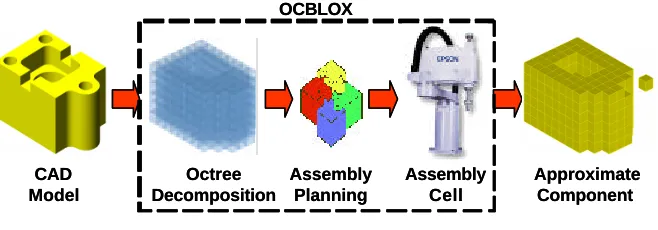
different sizes and materials. An overview of the OcBlox system is shown in Fig. 1. This paper
describes the assembly planning system developed to support the OcBlox system. This assembly
CAD Model Octree Decomposition Assembly Planning Assembly Cell Approximate Component OCBLOX CAD Model Octree Decomposition Assembly Planning Assembly Cell Approximate Component OCBLOX
Figure 1. Overview of the OcBlox system.
The rest of this paper is organized as follows. Section 2 provides a literature review regarding the
assembly planning and the octree decomposition. Section 3 describes the robotic assembly cell
developed to carry out the assemblies. A description of the OcBlox assembly planning system is
presented in section 4. The results obtained from the implementation and testing of the system are
discussed in section 5. Finally the paper ends with the conclusions drawn from the research work.
2. Literature review
Assembly is an important stage in product development and accounts for a large proportion of the
manufacturing costs. However, assembly remains one of the least understood manufacturing processes,
Whitney et. al. (1999). Most assembly design in industry is based on the mating, aligning or offsetting of
the regular faces of each of the mating parts of the assembly, Lin and Farahati (2003). The following
paragraphs summarise some research work related to the assembly planning (Homem and Lee, 1991;
Kai-I and Tai-His, 1995; Schmidt and Jackman, 1995; Swaminathan and Suzanne, 1996; Kaufman et.
al., 1996; Wilson, 1996; Sundaram et. al., 2001; Mascle, 2002).
2.1. Automatic assembly planning
assembly planning are: assembly sequence representation, generation and evaluation; planning process
accuracy and efficiency; CAD program integration; and task and motion planner integration. A
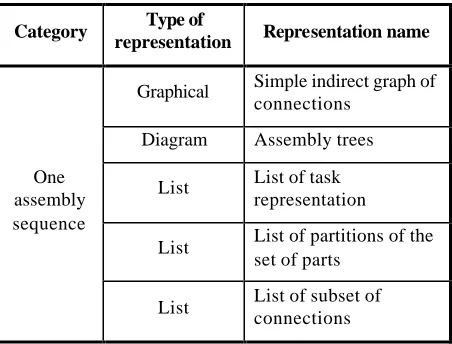
classification of assembly representation methods reported in the literature is shown in Table 1.
Assembly sequence generation has primarily focused on algorithms for the fast and efficient generation
of feasible assembly plans. Most of the assembly sequence generators transform the problem of
generating assembly sequences into the problem of generating disassembly sequences. A categorization
of the assembly sequence generation methods reported in the literature is shown in Table 2. Testing the
feasibility of assembly plans must consider several feasibility issues such as: geometrical, mechanical,
manipulability, accessibility, stability, visibility, and material. Geometrical feasibility is one of the most
important constraints because it checks if the assembly or removal of a part will collide with other parts;
typical test methods are: visibility, solid sweeping, stereographical projections of c-space obstacles,
graph method, electrical field, using floorgraphs, and ray testing. Assembly plan evaluation depends on:
tool changes, orientation changes, complexity of the assembly, assembly time, similar assembly
[image:4.596.185.411.533.705.2]operations, cost, and parallelism.
Table 1. Methods for representing assembly plans.
Category Type of
representation Representation name
One assembly sequence
Graphical Simple indirect graph of connections
Diagram Assembly trees
List List of task representation
List List of partitions of the set of parts
List List of binary vectors
A set of assemblies sequences
Graphical Directed graphs
Graphical AND/OR graphs
Graphical Directed assembly state vector graph
Graphical Precedence graphs
Graphical Petri nets
Diagram Liaison diagram
Function Establishment conditions
[image:5.596.182.412.105.294.2]List Precedence relationship
Table 2. Methods for the generation of assembly plans.
Category Description
Precedence knowledge
Use of precedence constraints to generate feasible assembly sequences.
Grouping components
Grouping the components of a product according to their features and similarities.
Forming subassemblies
By forming subassemblies based on some specific preferences.
Graphical approach
Using tracking or cut-set methods based on graphical representation of assembly sequence(s) or part -connection diagram(s).
Genetic search Use of genetic algorithms to obtain assembly plans.
Assembly state codification
Assembly states are codified and the assembly sequences are generated according to this codification.
Virtual Virtual assembly of components.
Motion based Assembly planning based on a motion planning method.
Random approach
Use of randomised methods like the Road Map approach.
Feasibility decompositions
Test the feasibility of separating the components from the assembly product.
assembly sequence generation, 2) assembly sequence evaluation, 3) simulation, and 4) robot instruction
generation. The majority of these assembly planners have been tested with a relative small number of
components (10 to 20 components).
2.2. Manual assembly planning
Historically assembly plans were selected by engineers only after the product design had been
completed, approved and authorized; there were some guidelines to plan the manual assembly.
Nowadays these assembly guidelines comprise a multidisciplinary combination of experiential, analytical
and theory-based recommendations. Human factors are decisive in assembly rationalization. Worker
performance is limited in terms of speed, stamina, and accuracy. Manual assembly has been improved
by better design of the workplace and substitution of muscle power by other energy sources.
Manual assembly has two advantages: 1) it applies simply and less costly hand tools, and 2) a greater
variation in part dimensions can be tolerated. In manual assembly, control of motion, decision-making
capability and flexibility, assuming well-trained operators, are superior to current machines. At times, it
is economical to provide operators with assistance (fixtures, gauges, computer displays, assembly plans,
etc.) to reduce the assembly time and errors. For these reasons, there are still many jobs that companies
prefer to assign to humans, such as in the automotive industry. These jobs are often repetitive, involving
visual inspection by a single worker at a single station and require dexterity not available to robotic
process grippers. Workstations for manual assembly tend to involve bulk, or flexible, materials with
2.3. Octree decomposition
The OcBlox system (Fig. 1) applies Octree decomposition to CAD models or assemblies to turn them
into approximate Octree models, Medellín et. al. (2006). The Octree decomposition technique is a
hierarchical tessellation that subdivides a volume into octants (cubes) of varying sizes. The relationship
among cubes is a hierarchical tree structure, where each branch is identified by the relative position of
the octant in its parent node. Octants can be classified as full, empty or boundary, depending on their
relative location in the CAD model: inside, outside or partially inside, respectively. For maximum
approximation, full and boundary octants are included in the approximate model. The octree
decomposition can be controlled by different criteria such as the maximum level of decomposition or the
minimum size of octant. At the end of the decomposition process, the list of octants will form an
approximate representation of a CAD model.
In the OcBlo x system the octant sizes are limited to particular sizes according to the capability of the
manufacturing process. To control the sizes of cubes between a minimum value smin and a maximum
value smax, the OcBlox system uses the fixed-size-range decomposition approach, Medellín et. al.
(2006). An optimization process is also performed by the system to reduce the number of cubes in the
Octree model. In this optimisation process each group of eight adjacent cubes is replaced by one larger
cube, Medellín et. al. (2008).
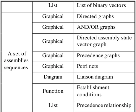
3. Assembly cell
A. Robotic system: an Epson® SCARA ES653S industrial robot (nominal repeatability ±0.02 mm) and
an Epson® SRC320 ABS multi-task controller with 16 I/O that can be read and generated via the
SPEL API.
Workspace Feeding
system
cubes
Robot
Binding system Gripping
system
Octree model Workspace
Feeding system
cubes
Robot
Binding system Gripping
system
[image:8.596.153.438.197.337.2]Octree model
Figure 2. Octree assembly cell.
B. Feeding system: stores and feeds the cubes to the assembly cell using a belt conveyor and several
adjustable-width lanes enabling the automatic alignment and placing of the cubes for picking. At each
lane a sensor controls the automatic feeding of cubes.
C. Binding system: consisting of an adhesive bath into which each cube being assembled is immersed
before its assembly. A cyanoacrylate-based adhesive is used because of its fast curing and high bond
strength; in this case Loctite® 426 with bond strength to aluminium of 2045 psi and a curing speed of 5
seconds for 40% of the full cured strength and 60% of relative humidity (The Design Guide for Bonding
Metals, 2004).
D. Gripping system: consists of a vacuum cup (10 mm diameter) attached to the robot arm. This
gripper uses the top face of a cube to grasp it but without obstructing other faces so they are clear for
E. Workspace: the current configuration of the assembly cell has a workspace area of 600 × 300 × 200
mm. A square support is fitted at the origin of the workspace to provide alignment during assembly.
F. Raw material: aluminium solid cubes of 10, 20, and 40 mm are used. These sizes were selected
based on the series of preferred numbers ISO R10, the commercial sizes of aluminium square bars, and
the dimension of the gripper.
4. OcBlox Assembly Planning (OAP) system
The OcBlox Assembly Planning (OAP) system comprises three main modules: a) assembly sequence
generator (ASG); b) assembly sequence evaluator (ASE); and c) assembly sequence translator (AST),
as shown in Fig. 3. The input data to the OAP system is an octree model which can be obtained by an
octree decomposition of the CAD model to be constructed. The output data of the OAP system are the
assembly instructions for robot and/or manual assembly.
Assembly Sequence Generator (ASG)
Generation of feasible assembly sequences
Assembly Sequence Evaluator (ASE)
Evaluation of assembly sequences
Assembly Sequence Translator (AST)
Generation of assembly instructions for robot and manual assembly Octree Model
Assembly instructions
OcBlox Assembly Planning (OAP) system
Assembly sequences
Optimal assembly sequence
Assembly Sequence Generator (ASG)
Generation of feasible assembly sequences
Assembly Sequence Evaluator (ASE)
Evaluation of assembly sequences
Assembly Sequence Translator (AST)
Generation of assembly instructions for robot and manual assembly Octree Model
Assembly instructions
OcBlox Assembly Planning (OAP) system
Assembly sequences
Figure 3. OcBlox assembly planning system.
According to the configuration of the assembly cell (Section 3), a general assembly process was defined
by three main moves: m1 from the feeder to the binding system, m2 from the binding system to the
workspace boundary, and m3 from the workspace boundary to the final assembly location. Assembly
preferences are defined in terms of four assembly variables limited to directions parallel to the
coordinate system axes (+X, +Y, +Z, –X, –Y and -Z), namely:
(i) First axis: progress assembly direction of cubes.
(ii) Second axis: progress direction of the first axis.
(iii) Build axis: progress direction of second axis.
(iv) Assembly trajectory: approach direction to assemble a cube.
The first, second and build axes preferences are used to define the way in which the assembly of a
component must progress, and they are used for both robot and manual assembly. On the other hand,
the assembly trajectory is just used for the robot assembly since in the manual assembly the person may
not follow this preference of the motion.
4.1. Assembly sequence generator (ASG)
If octants are always added to the assembly sequence in a predefined collision-free order, the assembly
plan will then be geometrically feasible; this is the basis of the modular assembly algorithm, Medellín
et. al. (2006), which is used by the ASG to generate feasible assembly sequences of Octree models.
using a predefined collision free order of each octant and its children. This octants-assembly order is
defined by the assembly variables.
To overcome the problems related to mechanical feasibility, manipulability and accessibility, the
following two conditions were established in the assembly sequence generation process: (1) a bottom up
build process is always used; (2) no cubes above the height level of the cube being assembled and along
the gripper approach direction can be assembled prior to it. These two conditions and the configuration
of the assembly cell mean that the possible directions of the assembly growth and the trajectory used to
position individual blocks were restricted to 36 discrete combinations. The possible values of the
[image:11.596.172.422.424.646.2]assembly variables are shown in Table 3, which lead to 36 feasible assembly sequences.
Table 3. Feasible values for the assembly variables.
Assembly sequences
First axis
Second axis
Build axis
Assembly trajectory
1 – 3 X Y Z -X -Y -Z
4 – 6 X Z Y -X -Y -Z
7 – 9 Y X Z -X -Y -Z
10 – 12 Y Z X -X -Y -Z
13 – 15 Z X Y -X -Y -Z
16 – 18 Z Y X -X -Y -Z
19 – 21 X -Y Z -X Y -Z
22 – 24 X Z -Y -X Y -Z
25 – 27 Z X -Y -X Y -Z
27 – 30 Z -Y X -X Y -Z
31 – 34 -Y X Z -X Y -Z
34 – 36 -Y Z X -X Y -Z
The cube fastening mechanism considered is an instant adhesive; therefore, unstable assembly conditions
and rigidity. A stability algorithm was developed to find unstable assembly conditions by considering
gravitational forces. When an octant is found to be unstable, the algorithm searches for adjacent empty
octants and adds them to the octree model as non-glued supporting cubes that are easily removed after
building. The stability algorithm also performs stability checks of supporting cubes being added to avoid
new unstable conditions. Adjacent octants are found using the neighbour finding method proposed in
Samet Hanan (1989). A part orientation analysis was also developed to analyse different orientations of
the octree model and minimise the number of supporting cubes needed. Six orthogonal orientations
parallel to the coordinate axes were considered with the optimal orientation being the one requiring the
least supports. More details of the stability and part orientation algorithms can be found in Medellín et.
al. (2008).
4.2. Assembly sequence evaluator (ASE)
The ASE module finds the optimal assembly sequence from the set of feasible assembly sequences
previously generated in the ASG module. The assembly sequence evaluation depends on weighted
criteria such as: tool changes, orientation changes, fixture complexity, directionality, travelled distance,
assembly time, similar assembly operations, cost, and parallelism. Since in an octree model all the parts
are cubes assembled using the same tooling, the most significant criterion considered is the travel
distance, i.e. the robot’s assembly path length, which can be estimated as:
)
( 2 3
1 1 i i
n
i i
T d d d
d = ∑ + +
= (1)
travel distances for the motions m1, m2 and m3 respectively. These distances depend on the locations
of the feeder, the binding system and the assembly trajectory. Since the location of the feeder and the
binding system are fixed and depend on the assembly cell configuration, the travel distance will vary only
if the assembly trajectory varies. Thus, the ASE module computes the travel distance for each assembly
sequence and selects the one with the minimum travelled distance. For manual assembly, this evaluation
process can be also used; however, as it was mentioned before, there is no guarantee that the person
will perform the assembly in the trajectory defined since humans move intuitively.
4.3. Assembly sequence translator (AST)
The AST is responsible for generating the assembly plan or assembly instructions to perform the robot
(automatic) and/or manual assembly.
4.3.1. Automatic assembly
The AST module generates the robot instructions in the SPEL language of the robot controller which
are used in the OAP application program. In this way, the OAP program generates the robot
instructions required to perform the assembly, including the control of all the variables required and
defined by the user (e.g. speed, acceleration, gripping, glue application, etc.). The synchronization
between the robot and the OAP system is direct and there is no need to export or import robot
instruction files.
4.3.2. Manual assembly
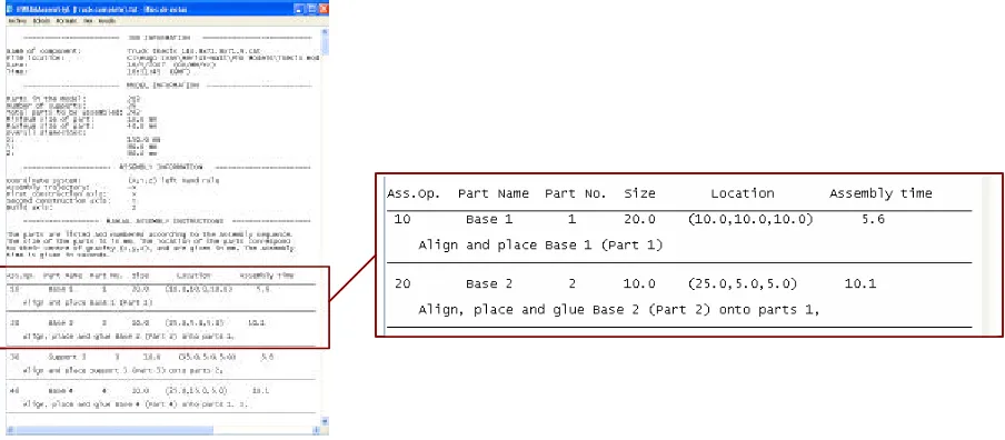
Manual assembly planning considers the generation of the instructions required to manually assemble the
manual assembly instructions as a separate text file which can be opened or printed by the user to be
used during the assembly process. The assembly instructions file provides the job information: file name,
file location, current date and time; the model information: number of parts and supports, total number of
parts to be assembled, minimum and maximum size of the parts and overall dimensions of the
component; the assembly information: coordinate system and assembly preferences; and assembly
instructions: assembly operation, part number, size, location, adjacent parts, estimated assembly time,
and assembly directions. The assembly operations and parts are ordered and numbered according to
the assembly sequence. The assembly instructions comprise information related to the adjacent parts to
the part being assembled, information regarding if the part is acting as a support or not, and assembly
instructions such as align, place, glue,etc. Figure 4 shows an example of the assembly instructions
[image:14.596.71.523.449.647.2]generated by the system, where the estimated assembly time is also included.
The assembly time for each manual assembly operation is estimated based on the Methods-Time
Measurement (MTM-1) system, ), Niebel and Freivalds (2004), which uses the TMU as the standard
unit time (1 TMU = 0.00001 hour. The assembly time of an ordinary part and an ordinary support are
280.9 TMU (10.1124 s) and 154.3 TMU (5.5548 s), respectively. These unit times have been
estimated based on the configuration of the assembly workspace and the MTM analyses shown in
Tables 4 and 5. Based on these analyses, the assembly time required to manually construct a
[image:15.596.165.432.364.690.2]component is estimated by the system.
Table 4. MTM analysis to assemble an ordinary part.
No. Description Basic
motion
Time (TMU)
1 Reach part from feeder R25B 22.9
2 Get part from feeder G1B 3.5
3 Move part to the glue system M12C 15.2
4 Turn part to apply glue on face 1 M1B 2.9
5 Foot motion to apply glue FM 8.5
6 Waiting time to apply glue W 27.7
7 Turn part to apply glue on face 2 M1B 2.9
8 Foot motion to apply glue FM 8.5
9 Waiting time to apply glue W 27.7
10 Regrasp part G2 5.6
11 Turn part to apply glue on face 3 M1B 2.9
12 Foot motion to apply glue FM 8.5
13 Waiting time to apply glue W 27.7
14 Move part to the assembly
workspace
M15B 15.8
15 Eye focus on the assembly EF 7.3
16 Position part P3NSE 47.8
17 Regrasp part G2 5.6
18 Apply pressure APA 10.6
19 Release part into position RL1 2.0
20 Eye focus on the assembly
instructions
EF 7.3
21 Eyes travel to feeder ET25/15 20
Table 5. MTM analysis to assemble an ordinary support.
No. Description Basic
motion
Time (TMU)
1 Reach support from feeder R25B 22.9
2 Get support from feeder G1B 3.5
3 Move support to assembly workspace
M25C 27.3
4 Eye focus on the assembly EF 7.3
5 Position support P3NSE 47.8
6 Regrasp support G2 5.6
7 Apply pressure APA 10.6
8 Release support into position RL1 2.0 9 Eye focus on the assembly
instructions
EF 7.3
10 Eyes travel to feeder ET25/15 20
Total 154.3
The manual assembly function has been designed for components that have been turned into octrees,
but its use can be extended to components that do not have any particular, or regular, shape. The
manual assembly function is also able to generate assembly instructions in different languages such as
English and Spanish.
5. Discussion of results
The OAP system has been implemented in Visual C++ using the ACIS® geometric modelling kernel to
support the geometric operations. The User Interface (UI) facilitates interaction and visualization of
octree decomposition and optimization, automatic and manual assembly planning, process authoring and
testing, assembly instruction generation for robot and manual (English or Spanish) assembly, and
performance analysis of the system.
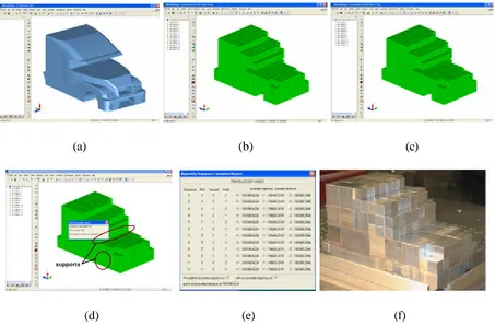
The capability of the OAP system has been tested with the construction of several components. As an
example, the construction of the truck component shown in Fig. 5a is presented. The octree
decomposition led to an octree model comprising 476 cubes of 10, 20, and 40 mm, Fig. 5b. After
optimizing this model, the number of octants was reduced to 203 cubes as shown in Fig. 5c. The
stability analysis of this model led to the addition of 39 supports, Fig. 5d. The assembly planning was
then carried out and the results suggested an optimal assembly sequence with a first, second, build and
assembly trajectory preferences of +X, +Y, +z and –X, respectively, and with a travelled distance of
161,098 mm, Fig. 5e. This sequence was used to construct the final component in the robotic assembly
cell, Fig. 5f. The time for the robot to assemble the model was 39 minutes, and the total production time
including the assembly planning was 1hr 5min 29s.
(a) (b) (c)
supports supports
[image:17.596.72.525.394.692.2]
(d) (e) (f)
supports, e) assembly planning, f) final component.
The robot assembly planning has been tested successfully by constructing several components. The
results have demonstrated that the OAP system is able to generate feasible assembly plans for a robot
to assembly Octree models. The performance of the assembly cell led to an assembly unit time of 9.66
s/cube, which was estimated using the information obtained from the construction of several
components.
5.2 Manual Assembly Planning
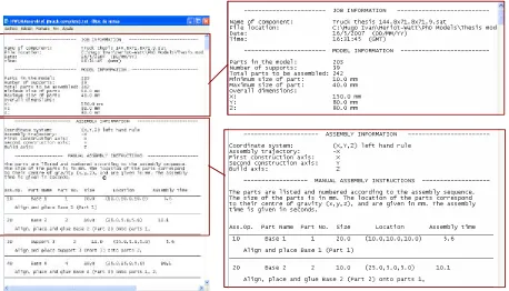
Manual assembly instructions of the truck component were also generated as a separate file as shown in
Fig. 6. These instructions detail the assembly operations required to perform the assembly and the
information regarding the assembly job. According to this manual assembly plan, 242 manual assembly
operations are required involving placing, aligning and gluing the parts at a specific location specified by
coordinates and adjacent parts. The assembly time to perform the manual assembly is 2266.6 seconds
(37 min 46.6 s), which is slightly smaller than the robot assembly time of 39 min. It should be noticed
that this assembly time is an estimation based on the assembly units 10.11 s/cube and 5.55 s/support
c c
Figure 6. Manual assembly instructions for the truck component.
Several experiments were performed with different people and using a benchmark assembly (which had
a smaller number of parts than the truck component). Each person in the experiment performed the
assembly three times using just one hand. From the experiments carried out it was observed that the
average unit time to assemble a cube was 2.5 s, which is smaller than the estimated time using the MTM
analysis (10.11 s) and the time obtained using the robot cell (9.66 s/cube). This difference may be
explained as follows. It was observed that the third assembly trial of each person was faster than the
first and the second trials, which suggests that people get faster as they get more experience or training.
It was also clear that once the people got to know the components to be assembled, they performed the
assembly using less motions (i.e. an optimal trajectory) without even having to look at the assembly plan.
to automatic machines. Moreover, position, speed and acceleration during the assembly are intuitively
calculated by humans and may vary from person to person. On the other hand, robot motions are
inflexible so the robot has to perform the assembly using the defined motions even though they may not
be the optimal for each part. Another important observation is the difficult and time consuming process
of reading assembly instructions when people are performing assemblies with many parts. People
suggested including pictures in the assembly plan so they can understand faster the assembly
instructions. People do not like reading positions or locations that are provided by coordinates, they
prefer pictures instead. Tiredness is an important aspect that should be taken into account when
components with large number of parts are assembled by humans. This is an advantage of robots over
humans since they are machines and tiredness does not have an impact on their performance. In these
experiments tiredness was not evaluated.
5.3 OAP system performance
The OAP system has been proved to be a feasible robot and manual assembly planning system. The
performance of the system has been evaluated using several components and the results have indicated
the following general performance values:
- Time to generate an assembly sequence: 0.843 s.
- Time to evaluate the assembly sequences: 3.78 s.
- Time to translate an assembly sequence: 2 min.
These values were estimated with the construction of several components, having a 289 cubes octree
the assembly planning does not make use of complex operations, such as Boolean operations, ray firing,
sweeping, genetic algorithms, etc., that are computationally expensive and that are used by most of the
assembly planners reported in the literature, see Table 2. Thus, it can be said that the octree
decomposition represents a technique that can be used for fast assembly planning of a large number of
parts. However, one disadvantage of this technique is that it approximates a part instead of using the
actual part. On the other hand, when a component comprising several parts is intended to be
assembled, the system should be able to identify the independent parts and decomposed them
separately. Then, the octree models of the parts should be assembled in an environment surrounded by
these octree models. In other words, the system should be able to plan the assembly of several octree
models. For this reason, more research work is being carried out to solve the current limitations of the
OAP system.
6. Conclusion
The octree decomposition technique has been proved to be an effective assembly planning tool. As a
result, an assembly planning system, named as OcBlox Assembly Planning (OAP) system, has been
developed and presented in this paper. After the implementation of the OAP system, the results have
showed that the assembly planning of CAD models for either robot or manual assembly can be
performed using an octree decomposition approach. Assembly plans for automatic and manual
assembly can be generated automatically by the proposed system, which is a novelty since there are no
assembly planning systems for manual assembly reported in the literature. Moreover, since the OAP
the assembly planning is relatively fast and it can be performed on components comprising hundreds of
parts.
Future work will focused in the solution of the current limitations of the OAP system, including the
generation of manual assembly plans with pictures, assembly precedence diagrams for cube-based
fabrications, e.g. Soma puzzles or CAD assemblies that have been turned into Octrees, Sung (2001).
Also, the potential applications to support cube construction at micro or macro scales including the
precision of manipulators and joining technologies, is also considered as future work.
Acknowledgment
This research work was supported by the EPSRC grant GR/R35285/01. The first author
acknowledges the support from the Fund for Research Support (FAI) of the Universidad Autónoma de
San Luis Potosí and the support from the PROMEP program of SEP in Mexico.
References
Chen Y. H., Song Y., “The development of a layer based machining system” Computer Aided Design,
33, 2001, pp. 331-342.
Frank Matthew, Sanjay B. Joshi, and Richard A. Wysk, “CNC-RP: A technique for using CNC
machining as a rapid prototyping tool in product/process development”, Proceedings of the 11th
annual industrial engineering research conference, Orlando, Florida. May 19-22, 2002.
Gibson Ian, “A discussion on the concept of a flexible rapid prototyping cell”, Rapid Prototyping
Homem de Mello Luiz S., Lee Sukhan, “Computer-Aided Mechanical Assembly Planning”, foreword
by George A. Bekey, Kluwer Academic Publishers, 1991.
Hsuan-kuan Huang, Lin Grier C. I., “Rapid and flexible rapid prototyping through a dual robot
workcell”, Robotics and Computer Integrated Manufacturing, 19, 2003, pp. 263-272.
Junghoon Hur, Lee Kunwoo, Zhu-hu, Kim Jongwon, “Hybrid rapid prototyping system using machining
and deposition”, Computer Aided Design, 34, 2002, pp. 741-754.
Kai-I Huang and Tai-His Wu, “Computer-Aided Process Planning for Robotic Assembly”, 17th
International Conference on Computers and Industrial Engineering, 29, 1-4, 1995, pp. 653-657.
Karunakaran K.P., P. Vivekananda Shanmuganathan, Sanjay Janardhan Jadhav, Prashant Bhadauria,
Ashish Pandey, “Rapid prototyping of metallic parts and moulds”, Journal of Materials
Processing Technology, 105, 2000, 371-381.
Kaufman Stephen G., Wilson Randall H., Jones Rondall E., Calton Terri L and Ames Arlo L., “The
Archimedes 2 Mechanical Assembly Planning System”, Procc. of the 1996 IEEE International
Conference on Robotics and Automation, 1996, pp. 3361-3368.
Lin Y. J. and Farahati R., “CAD-Based Virtual Assembly Prototyping – A Case Study”, The
International Journal of Advanced Manufacturing Technology, 21, 2003, pp. 263-274.
Mascle Christian, “Feature-based assembly model for integration in computer-aided assembly”,
Robotics and Computer Integrated Manufacturing, 18, 2002, pp. 373-378.
Medellín H., Corney J., Davies J.B.C., Lim T., Ritchie J. M., “Algorithms for the physical rendering and
Medellín H., Corney J., Davies J.B.C., Lim T., Ritchie J.M., “Octree Based Production of Near Net
Shape Components”, IEEE Transactions on Automation Science and Engineering, vol. 5, No. 3,
July 2008, pp. 457-466.
Niebel B. W., Freivalds A. Ingeniería Industrial, Métodos estándares y. diseño del trabajo. Ed.
Alfaomega. ED. 11. a. México 2004
Samet Hanan, “Neighbour finding in images represented by octrees”, Computer Vision, Graphics and
Image Processing, 46, 1989, pp. 361-386.
Schmidt, L. C., Jackman, J., “Evaluating assembly sequences for automatic assembly systems”, IIE
Transactions, 27, 1995, pp. 23-31.
Sundaram Sujay, Remmler Ian and Amato Nancy M., “Disassembly Sequencing Using a Motion
Planning Approach”, Proceedings of the 2001 IEEE International Conference on Robotics
and Automation, May 21-26, 2001, pp. 1475-1480.
Sung, R. C. W., “Automatic Assembly Feature Recognition and Disassembly Sequence Generation”,
Ph.D. Thesis, Heriot-Watt University, Edinburgh, Scotland, 2001.
Swaminathan Arun and Suzanne Barber K., “An Experience-Based Assembly Sequence Planner for
Mechanical Assemblies”, IEEE Transactions on Robotics and Automation, 12, 2, 1996, pp.
252-267.
“The Design Guide for Bonding Metals”, Loctite®, Henkel Technologies, 4, 2004,
http://www.loctite.com.
Whitney D.E., Mantripragada R., Adams J. D. and Rhee S. J., “Designing assemblies”, Research in
Wilson Randall H., “Geometric Reasoning about Assembly Tools”, Technical report SAND95-2423,