City, University of London Institutional Repository
Citation
:
Beshara, F.B.A. (1991). Nonlinear finite element analysis of reinforced concrete structures subjected to blast loading. (Unpublished Doctoral thesis, City University London)This is the accepted version of the paper.
This version of the publication may differ from the final published
version.
Permanent repository link: http://openaccess.city.ac.uk/7683/
Link to published version
:
Copyright and reuse:
City Research Online aims to make research
outputs of City, University of London available to a wider audience.
Copyright and Moral Rights remain with the author(s) and/or copyright
holders. URLs from City Research Online may be freely distributed and
linked to.
City Research Online: http://openaccess.city.ac.uk/ [email protected]
NONLINEAR FINITE ELEMENT ANALYSIS OF REINFORCED CONCRETE STRUCTURES SUBJECTED TO BLAST LOADING
by
Fouad Bakheet Aboud Beshara
Thesis submitted for the Degree of
Doctor of Philosophy
City University
Department of Civil Engineering London
ERRATA
Page 80, Line 10: equation (3-53) should read equation (3-55) Page 84, equation (3-64): C should read Cr
Page 131, Line 17: when should read where Page 137, Equation (5-39) should read
& + E() (0. - t) E
Page 137, Equation (5-42) should read
= 2 C (c' - C t)
C Cd c
Page 142, Line 23: equation (5-9) should read equation (5-11) Page 149, Line 5: radical should read radial
Page 166, Equation (5-14) should read
&+E (o-t5) -CE=0
Page 172, Table 5-2: Values of coefficient B should read 0.915, 0.904, 0.943, 0.863
Page 182, Figure 5.9: c should read
vp
Page 183, Figure 5.10: c should read c'
VP VP
Page 201, Equation (6-21) should read
d =---(d -2d +d )
n
At2 n+1 n n-i Page 201, Line 2: d should read d
n+1 n+i
Page 255, Line 7: overpressure should read load
ACKNOWLEDGEMENTS
The research described in this thesis was made at City University under the supervision of Professor K S Virdi, to whom the author wishes to express his profound gratitude for his invaluable advice and constructive guidance throughout the entire course of this study.
Sincere thanks go to the author's friend Dr S El-Shorbani for the initial instigation for pursuing the research studies and his continuous patronage in my endeavours to finish this project.
The author also wishes to express his appreciation to his friend, Ronald Wilkins for his encouragement and useful discussions on many occasions.
The author is grateful to the staff of City University Library, especially Mrs Sheila Munton and Mr John Adams, for their help in obtaining many of the papers referenced herein. Thanks are also due to the operating and advisory staff of the Computer Centre at City University for their assistance in computational matters.
Special thanks are also extended to Mrs Pat Walker for her care, skill and patience in typing this thesis.
The author acknowledges the partial financial support of the Overseas Research Students Awards Scheme during the period October 1987 to June 1989 of this investigation.
SUMMARY
This thesis is concerned with the development of finite element techniques for nonlinear dynamic analysis of planar and axisymmetric reinforced concrete structures subjected to blast loading. The main aspects of numerical modelling process to simulate blast loads, structural geometries and material behaviour are addressed. Major attention has been focused on the development of appropriate history and rate dependent constitutive models for concrete and steel where several material nonlinearities are considered in tension and compression as well as the strain rate effects. Computational algorithms and modified solution procedures have been also developed and coded, which are applied to various structural problems under severe dynamic loading conditions.
The basic characteristics of the explosion and blast wave phenomena are presented along with a discussion of the modelling of blast pressures in the free-field due to unconfined and confined explosions. Predictions methods are considered which allow an estimation to be made of the associated internal or external airbiast loads on above-ground structures.
The dynamic equilibrium equations for a blast-loaded structure are derived using the principle of virtual work in total Lagrangian approach. The finite element discretization of the equations of motion in space is adopted in accordance with isoparametric formulations. The steel reinforcement is modelled by bar or membrane elements embedded within the basic 8-node isoparametric concrete element. Perfect bond is assumed between steel and surrounding concrete. The integrals, which define the element matrices and vectors are obtained numerically by use of Gaussian quadrature. Hinton's lumping scheme has been employed to generate the lumped mass matrix from the consistent mass matrix for both concrete and steel.
crushing conditions. The viscoplastic strain rate is calculated by a rate dependent associated flow rule in which the fluidity parameter is derived as a function of the effective strain rate. In tension, concrete is modelled as a linear elastic strain softening material where crack initiation is controlled by a rate dependent strain criterion. The smeared crack approach is employed to simulate cracks, post-cracking behaviour is governed by an objective nonlinear softening rule based on concrete fracture energy and crack characteristic length. Shear transfer across the cracks is considered by a suitable simple model. The strain rate-induced anisotropy is introduced by employing different rate sensitivity functions for tension and compression. Steel is modelled as a uniaxial strain rate dependent elasto-viscoplastic material
in tension and compression in which the yield stress and the fluidity parameter are strain rate sensitive. The identification of model parameters of concrete and steel are performed using some standard experimental results.
A modified explicit central difference scheme based on the Newmark- method is proposed to advance the nodal displacements, velocities and accelerations in time. Numerical stability has been controlled using appropriate time increments and energy balance check. The details of an explicit Euler scheme for time integration of time rate constitutive equations of concrete and steel are described in which a semi-empirical a priori stability criterion for the definition of time step length is proposed.'
Page
2.
u/ui
iv-ix x
xi-xvi xvii-xxv
TABLE OF CONTENTS
Acknowledgements Summary
Table of contents List of Tables List of Figures List of Notations
CHAPTER 1 INTRODUCTION
1.1 General background
1.2 Statement of the problem
1.3 Scope and objectives of the present research 1.4 Layout of the thesis
1/2 3-5 5-8 8-11
CHAPTER 2
REVIEW OF CONSTITUTIVE THEORIES FOR CONCRETE AND REINFORCING STEEL
2.1 Introduction 12/13
2.2 Observed experimental concrete behaviour 13/14 2.2.1 Structure of concrete and microcracking 14-16 2.2.2 Mechanical properties under short term static 16-20
loading conditions
2.2.3 Mechanical properties under dynamic loading 20/21 conditions
2.3 A review of constitutive models of uncracked 21/22 concrete
2.3.1 Elasticity based models 22-24
2.3.2 Visco-elasticity based models 24-26
2.3.3 Plasticity based models 26-29
2.3.4 Viscoplasticity based models 29-31
2.3.5 Endochronic models 31/32
2.3.6 Recent modelling approaches 32-34
2.4 Review of cracked concrete modelling 34
2.4.1 Crack initiation criteria 34/35
54/55 55 55/56 57/58 58/59 59-61 61 61-64 64-66 66-69 69-72 72/73 73-77 77 77-78 79-82 82-85 85/86 87 87-90 Page 2.4.3 Tension stiffening of cracked concrete 38-40
2.4.4 Crack interface shear transfer 40/41
2.5 Review of material modelling of reinforcing steel 41 2.5.1 Mechanical properties of steel in static and 42/43
dynamic loading conditions
2.5.2 Constitutive relationships for reinforcing steel 44/45 2.6 Concluding considerations for material modelling 46/47
of blast resistant reinforced concrete
CHAPTER 3
MODELLING OF' BLAST LOADING ON CONCRETE STRUCTURES
3.1 Introduction
3.2 Explosion and blast wave phenomena 3.2.1 The explosion process
3.2.2 Blast wave configuration 3.2.3 TNT equivalency
3.2.4 The blast scaling law
3.3 Modelling of airbiast loading due to external explosions
3.3.1 Overpressure loading parameters due to atomic weapons
3.2.2 Characteristics of overpressure loading due to conventional high explosives
3.3.3 Overpressure prediction due to unconfined vapour cloud explosion
3.3.4 Dynamic pressure prediction
3.3.5 Reflected overpressure prediction
3.3.6 External blast loads on above-ground structures 3.4 Airblast loading due to the internal explosions
and contact blast
3.4.1 Effects of confinement and venting 3.4.2 High explosive source
3.4.3 Combustible gas or dust mixtures with air 3.4.4 Contact blast
Page 3.5.2 Directly transmitted ground motion 90/91 3.5.3 Net ground shock loads on structures 91/92 3.6 Modelling considerations of blast loads for 92-95
nonlinear dynamic analysis CHAPTER 4
FINITE ELEMENT FORMULATION OF REINFORCED CONCRETE
STRUCTURES SUBJECTED TO BLAST LOADING
4.1 Introduction 103/104
4.2 Finite element discretization of dynamic 104 equilibrium equations
4.2.1 Virtual work analysis 104
4.2.2 Finite element spatial discretization 105/106 4.2.3 Dynamic equilibrium equations in semi-discrete 106/107
form
4.3 Isoparametric elements: Formulation and 107/108 numerical integration
4.3.1 Formulation of isoparametric element 108 characteristic matrices and vectors
4.3.2 Numerical integration 109/110
4.4 Modelling of mass matrix 110
4.4.1 Consistent mass matrix 110/111
4.4.2 Lumped mass matrix 111-113
4.5 Modelling of damping matrix 113/114
4.6 Finite element modelling of steel reinforcement 114
4.6.1 Reinforcement representation 114/ 115
4.6.2 Formulation of the embedded representation of 115-118 steel
4.7 The significance of some FE procedural factors in 118 the prediction of concrete structural behaviour
4.7.1 FE Mesh configuration 118/119
4.7.2 The integration rule related to concrete cracking 119/120 process
CHAPTER 5
Page 124/ 125 125-127 5.1 Introduction
5.2 Main characteristics of the proposed concrete model
5.3 Numerical modelling of concrete behaviour in compression
5.3.1 The failure surface
5.3.2 The initial yield and subsequent loading
127 128-130 130-132 surfaces
5.3.3 Strain rate sensitive hardening rule 132-135
5.3.4 Strain rate sensitive flow rule 135-141
5.3.5 Strain softening in compression 142/143
5.3.6 crushing of concrete 143-145
5.4 Numerical modelling of concrete tensile behaviour 145 5.4.1 Finite element representation of cracks 146/147 5.4.2 Strain rate sensitive cracking criterion 147-150
5.4.3 Strain softening rule 150-154
5.4.4 Shear transfer across the cracks 154/155
5.4.5 closing and opening of existing cracks 155/156 5.4.6 Compressive behaviour of cracked concrete 156/157 5.5 Constitutive relationships for concrete 157
5.5.1 Uncracked concrete 157/158
5.5.2 Cracked concrete 158-161
5.5.3 Transformation rule 161
5.6 Strain rate sensitivity functions of concrete 161 5.6.1 Rate sensitivity functions in compression 162 5.6.2 Rate sensitivity functions in tension 162/163
5.6.3 Strain rate induced anisotropy 163
5.7 Numerical modelling of steel reinforcement 163 5.7.1 Main characteristics of the proposed steel model 163/164 5.7.2 Dynamic yield stress and hardening rule 164/165
5.7.3 Strain rate sensitive flow rule 165-168
5.7.4 Stress-strain relationship of steel 169
5.8 Experimental characterisation 169-171
CHAPTER 6
6.1 Introduction
6.2 Time discretization of nonlinear dynamic equilibrium equations
6.2.1 Review of time integration methods
6.2.2 selecting solution procedure for the present analysis
6.2.3 Formulation of a modified form of explicit central difference scheme
6.2.4 Computational strategy aspects
6.3 Time discretization of the viscoplastic strain governing equations
6.3.1 The viscoplastic strain increments 6.3.2 Time increment definition
6.4 Selection of the time increment for nonlinear dynamic analysis
6.5 Some practical considerations in explicit integrations
6.5.1 Energy balance check
6.5.2 Control of spurious oscillations
CHAPTER 7
COMPUTER IMPLEMENTATIONS AND BRIEF PROGRAMS DESCRIPTION
7.1 Introduction
7.2 2D finite element dynamic analysis program 7.2.1 Characteristic features of FEABRS
7.2.2 Basic structural analysis facilities 7.2.3 General structure
7.3 Computer implementation of solution technique and material models
7.4 Pre and post-processing auxiliary programs
Page 192-194 194 194-198 198-200 200-203 203/204 204 /205 205 205-209 209-211 211/212 212-214 214 / 215
220 220 22 1-224 224-226 226-231 231/232 232/233 CHAPTER 8 NUMERICAL APPLICATIONS 8.1 Introduction
8.2 Simply supported reinforced concrete beam under impulsive concentrated loads
8.2.1 General background
8.2.2 Geometry, material properties and loading 8.2.3 Numerical model
8.2.4 Results
8.3 Clamped circular reinforced concrete slab under uniformly distributed jet force
8.3.1 General background
8.3.2 Geometry, material properties and loading 8.3.3 Numerical model
8.3.4 Results
8.4 Reinforced concrete beam subjected to uniformly distributed blast loading
8.4.1 Comparison with experiments
8.4.2 Description of the structure and material properties
8.4.3 Numerical modelling of the problem 8.4.4 Explosion loading data
8.4.5 Analytical results of the problem
8.5 Prametric study of concrete nonlinearity 8.5.1 Strain rate dependency effect
8.5.2 Concrete elastic limit in compression 8.5.3 Concrete cracking strain effect
8.5.4 Concrete fracture energy 8.5.5 Concrete tension softening
8.6 Discussion and concluding remarks CHAPTER 9
CONCULS IONS AND RECOMMENDATIONS 9.1 General conclusion
9.2 Specific conclusions 9.2.1 Modelling of blast loads 9.2.2 Spatial discretization
9.2.3 Modelling of material nonlinearity
9.2.4 Time discretization and solution techniques 9.3 Recommendations for future work
Page 240 240 240/241 241-246 246 24 6/247 247 247/ 248 248-252 253 253 253 /254 254 254/255 255-262 262 263 2 63/264 2 64/265 265/266 266/ 2 67 267/268
33 1/332 332 332/333 333 /3 3 4 334-337 337 /33 8 338-341
Table 2.1 4.1 5.1 5.2 5.3 6.1 6.2 6.3 7.1 7.2 7.3 8.1 8.2 8.3 Page 48 121 172 172 173 216 217 217 236 237 238 269 270 271
LIST OF TABLES
Summary of concrete dynamic tests data
Some characteristic vectors and matrices for two-dimensional solid mechanics applications Material constants of the proposed failure criteria
Material constants of the concrete fluidity parameter
Compound material constants of the proposed failure criteria
Step-by-step solution procedure of explicit central difference
Critical time step parameters identified from Watstein's (16] and Hatano's [17] tests
Critical time step of some concrete grades
(Assuming von Mises yield criterion, t = 10 sec1) The crack monitoring algorithm in FEABRS
Concrete viscoplasticity controlling algorithm in FEABRS
Steel viscoplasticity controlling algorithm in FEABRS
Material properties of Bathe's reinforced concrete beam [235]
Material properties of reinforced concrete circular slab (238)
LIST OF FIGURES
Figure Page
2.1 Stress-strain curves of concrete under uniaxial 49 compression
2.2 Stress-strain curves of concrete under uniaxial 49 tension [21]
2.3 Stress-strain curves of concrete under biaxial 50 stress (37]
2.4 Biaxial strength of concrete [37] 51
2.5 Concrete behaviour under triaxial stress [45] 52 2. 6 Typical stress-strain curves for steel 53
reinforcement (21]
2.7 Stress-strain diagrams for two steel specimens 53 at different rates of straining [28]
3.1 Variation of overpressure with distance from 96 centre of explosion at various times [119]
3.2 Shock wave reflection phenomena [119) 96
3.3 Blast wave load-time curve representations [126] 97 3.4 Maximum wave overpressure versus energy-scaled 98
distance for deflagrative explosions [115)
3.5 Energy-scaled impulse versus energy-scaled 98 radius for deflagrative explosions [115]
3.6 Pressure on front face of structure (126) 99 3.7 Pressure on rear face of structure (126) 99 3.8 Internal pressure loading at inner surface of 100
a structure [128]
3.9 Pressure-time trace for a typical internal 101 deflagrative explosion [116)
3.10 Peak quasi-static pressure for TNT explosion 102 in a structure (115]
3 • 11 Scaled blowdown duration versus scaled maximum 102 pressure for TNT explosion in structure [115)
4.1 Typical shape functions of 8-node isoparatnetric 122 element [27]
Page 5.]. 2D stress space representation of the concrete 174
const itut ive model
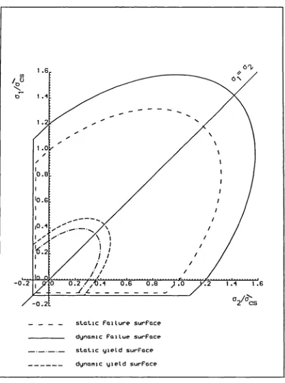
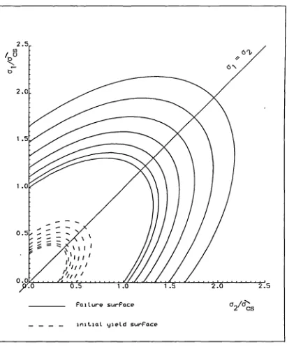
5.2 Effect of strain rate on the failure and initial 175 yield surfaces
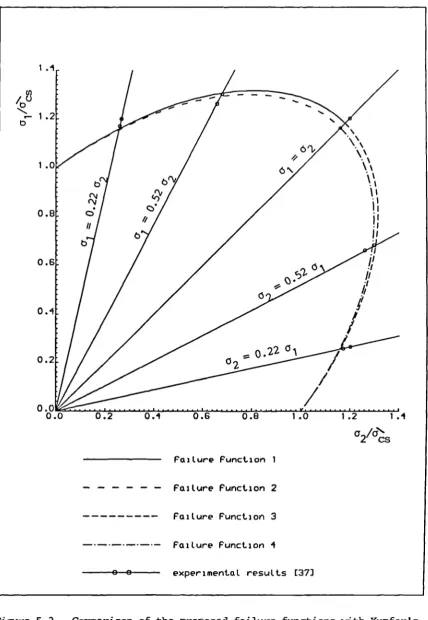
5.3 Comparison of the proposed failure functions with 176 Kupfer's results
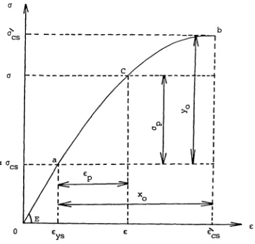
5.4 Uniaxial stress-strain diagram in the pre- 177 fracture range
5.5 Comparison of static hardening function with 178 Kupfer's uniaxial results
5.6 Dynamic hardening rule as influenced by strain 179 rate
5.7 Effect of strain rate on compression curves of 180 5.8 5.9 5.10 5.11 5.12 5.13 5.14 5.15 5.16 5.17 5.18 5.19 5.20 5.21 concrete
Fluidity parameter versus strain rate for different grades of concrete
Comparison of softening rule in compression with Kupfer's uniaxial results
Effect of strain rate on dynamic softening rule Stresses after crack initiation [27]
Cracking types for axisymmetric problems Strain softening curve with secant unloading and reloading [78]
Illustration of characteristic length for a prismatic control volume (78]
Possible crack configurations (27]
Dynamic tensile testing results reported in the literature (197]
Proposed tensile strength rate sensitivity function
Strain rate sensitivity functions of concrete in tension and compression
Uniaxial stress-strain diagram of steel
Strain rate sensitivity function of steel yield stress [196]
Dynamic stress-strain curves of steel [188, 189]
5.22 6.1 6.2 7.1 7.2 8.1 8.2 8.3 8.4 8.5 8.6 8.7 8.8 8.9 8.10 8.11 8.12 8.13 Page 191 218 219 234 235 272 273 274 275 276 277 278 279 280 281 282 283 284 Fluidity parameter plotted against strain rate
for steel
Critical time step versus strain rate for different grades of concrete
Critical time increment versus strain rate for steel
Flow diagram of FEABRS
Implementation flow chart of solution technique and rate dependent material models in FEABRS Bathe's beam details and finite element
idealization
Nonlinear dynamic response of Bathe's beam (criteria 1 and 2)
Nonlinear dynamic response of Bathe's beam (criteria 3 and 4)
Deformation and cracking history for the Bathe's beam
Horizontal displacement distribution along Bathe's beam at respective times
Vertical displacement distribution along Bathe's beam at respective times
Longitudinal stress distribution along Bathe's beam at respective times
Transverse stress distribution along Bathe's beam at respective times
Shear stress distribution along Bathe's beam at respective times
Maximum principal stress distribution along Bathe's beam at respective times
Minimum principal stress distribution along Bathe's beam at respective times
Effective strain rate distribution along Bathe's beam at respective times
8.14 8.15 8.16 8.17 8.18 8.19 8.20 8.21 8.22 8.23 8.24 8.25 8.26 8.27 8 • 28 8.29
8.30
8.31
Page Effective strain rate distribution of reinforcing 285 steel of Bathe's beam at various time stations
Circular slab details and finite element model 286 Nonlinear dynamic response of circular plate 287 Deformation and cracking history for circular 288 slab
Horizontal displacement distribution of the slab 289 at respective times
Vertical displacement distribution of the slab 290 at respective times
Radial stress distribution in r-direction of the 291 slab at respective times
Radial stress distribution in z-direction of the 292 slab at respective times
Shear stress distribution of the slab at 293 respective times
Hoop stress distribution of the slab at 294 respective times
Maximum principal stress distribution of the 295 slab at respective times
Minimum principal stress distribution of the 296 slab at respective times
Effective strain rate distribution of the slab 297 at respective times
Stress distribution in the radial reinforcing 298 steel of the plate at various time stations
Stress distribution in the hoop reinforcement 299 of the slab at various time stations
Effective strain rate distribution along the 300 radial reinforcement of the plate at various
time stations
Effective strain rate distribution along the 301 hoop reinforcement of the plate at various
time stations
8.32 8 • 33 8 • 34 8.35 8.36 8.37 8.38 8.39 8.40 8.41 8.42 8.43 8.44 8.45 8.46 8.47 Page 303 304 305 306 307 308 309 310 311 312 313 314 315 316 317 318 Details of Seabold's beam and finite element
idealization
Comparison of the predicted and measured central deflection-time history
Comparison of the analytical and experimental mid-span velocity history of the beam
Comparison of the predicted and measured
compressive strain history of concrete at beam mid-span
Comparison of the predicted and measured stress history of main reinforcement at mid-span of beam WE5
Comparison of the predicted and measured stress history of main reinforcement at mid-span of beam WE2
Comparison of the numerical and experimental reaction history at left-hand support
Deformation and cracking history for Seabold's beam
Horizontal displacement distribution along Seabold's beam at respective times
Vertical displacement distribution along Seabold's beam at respective times
Longitudinal stress distribution along Seabold's beam at respective times
Transverse stress distribution along Seabold's beam at respective times
Shear stress distribution along Seabold's beam at respective times
Maximum principal stress distribution along Seabold's beam at respective times
Minimum principal stress distribution along Seabold's beam at respective times
Page 8.48 Stress distribution of reinforcing steel of 319
Seabold's beam at various time stations
8.49 Effective strain rate distribution of reinforcing 320 steel of Seabold's beam at various time stations
8.50 The effect of strain rate on the nonlinear 321 response of Bathe's beam
8.51 The effect of strain rate on the nonlinear 322 response of Seabold's beam
8.52 Influence of the elastic limit on the nonlinear 323 response of Bathe's beam
8.53 Influence of concrete elastic limit on the 324 nonlinear response of Seabold's beam
8.54 Nonlinear response of Bathe's beam for different 325 cracking strains
8.55 Nonlinear response of Seabold's beam for 326 different cracking strains
8.56 Influence of concrete fracture energy on 327 nonlinear response of Bathe's beam
8.57 Influence of concrete fracture energy on 328 nonlinear response of Seabold's beam
8.58 Nonlinear response of Bathe's beam as influenced 329 by tension softening
A $ A V A w A yr AH a V
LIST OF MAIN NOTATIONS
* Blast loading parameters (Chapter 3) Internal surface area of the structure Vent area
Area of vented wall or roof
ground ground ground a h a 0 Cf C t C r C p C 0 D V D H d V g H TNT H exp AH f
Maximum airbiast-induced vertical acceleration
Maximum airbiast-induced horizontal acceleration
Peak directly transmitted vertical acceleration
Peak directly transmitted horizontal ground acceleration
Speed of sound at standard sea level
Drag coefficient for the front face of structure Drag coefficient for the roof of structure
Coefficient for pressure rise rate of confined deflagrative explosion
Compression wave seismic velocity of the soil Speed of sound in the undisturbed atmosphere
Maximum airbiast-induced vertical ground displacement
Maximum airbiast-induced horizontal ground displacement
Peak directly transmitted vertical ground displacement
Peak directly transmitted horizontal ground displacement
Acceleration due to earth gravity
Heat of detonation of Trinitrotolune, TNT Heat of detonation of explosive in question
i $ -I-1 5 1 r K g M S M su P P S P r P(t) P 0 P U P d P1 P qs P P V P C P ye P abs P ad R
The impulse of blast wave per unit of projected area
Energy-scaled impulse of blast wave per unit area The impulse of reflected shock wave per unit area Ratio of the smallest cross-sectional area of the enclosure in which the explosion occurs to the area of vent
Mach number corresponding to specific peak overpressure
Reference Mach number of the explosive fuel
Total airbiast pressures due to external explosion
Peak overpressure in the incident shock wave Peak overpressure in the reflected shock wave Overpressure-time function
Ambient pressure
Energy-scaled overpressure Peak dynamic pressure
Scaled initial gas pressure due to confined explosion
Peak quasi-static gas pressure due to confined explosion
Maximum internal pressure due to deflagrative confined explosion
The pressure at which the vent is created
Rate of pressure rise due to confined deflagration explosion
Rate of pressure relief by venting Absolute pressure at given time
R Characteristic distance of unconfined vapour cloud explosion
R Energy-scaled distance of unconfined vapour cloud explosion
r Radius of circular area over which the pressure due to contact blast is applied
r Radius of exploding charge
The smaller of the height of structure or one half of the structure width
Duration of equivalent pulse of initial shock wave loading due to confined explosion
Duration of equivalent pulse of reflected shock wave loading due to confined explosion
Arrival time of shock wave at a given location Duration of initial shock wave in the free field Duration of equivalent pulse of shock wave in the free field
Duration of equivalent pulse of dynamic pressure Intercept on time axis of initial decay slope of overpressure-time curve
Duration of dynamic pressure positive phase
Duration of equivalent pulse of reflected shock wave
Clearing time necessary for the decay of the reflected pressure to the side-on overpressure on the front face of the structure
The rise time of pressure on the front face of structure
Time needed for the pressure build-up on the near face of structure
The rise time of pressure on the roof of structure
Duration of equivalent pulse of the roof loading Blow-down time at which the pressure due to confined high explosive returns to ambient
t V t ag w w F w TNT w oxp V V V V H V vd V h U $ U U z p. p0 a C a A pp
Rise time to the peak airbiast-induced vertical ground velocity
Arrival time of the direct ground shock to a given location
Weight of explosive material
Weight of explosive fuel released into the atmosphere
Equivalent weight of TNT charge Weight of the explosive in question
(or V) Internal volume of the structure
Maximum airbiast-induced vertical ground velocity Maximum airbiast-induced horizontal ground velocity
Peak directly transmitted vertical ground velocity
Peak directly transmitted horizontal ground velocity
Shock front velocity
Peak wind velocity behind the shock front
Scaled distance or proximity factor of a given explosion
Dimensionless shock wave form parameter Yield factor of a given explosion
The ratio of specific heat of air Air density behind the shock front Air density ahead of the shock front
Scaled blow-down duration Vent area ratio (= A/A)
Ratio between vent area to internal volume of structure
B
B8
b, ID
0 C, Ce C
p D
d, d, d
F
d
9
S det S K,Ke
* Finite element and solution techniques parameters (Chapters 4, 6)
a a Time integration constants
o
Element strain displacement matrix of concrete Strain displacement matrix of reinforced bar or membrane
Rayleigh damping parameters
Global and element damping matrices
Acoustic wave speed of the structural material Stress-strain matrix
Nodal displacements, velocities and acceleration vectors
Element nodal displacements vector in the global coordinate system
Vector of externally applied airbiast nodal loads on the structure
Nodal airbiast-induced accieration vector in global coordinate system
Jacobian matrix
Determinant of Jacobian matrix
Global and element stiffness matrix
H, H8 Global and element mass matrix
m11 Diagonal term of lumped mass matrix for a typical node i
Diagonal term of lumped mass matrix for a typical node i due to steel bar or membrane
N, N8 Global and element shape functions matrix fl Integer suffix for time step number
nd Total number of degrees of freedom in the
structure
P Vector of nodal internal resisting forces
P Reinforcement contribution in the vector of nodal B
A
max
Ii
I
Q S 1 , S2 ti , t2 At
Atcr At: w
Wc n, int,
V,dV
Vector of total externally applied forces on structure
Steel material parameters of a priori stability criterion of time integration
Concrete material parameters of a priori
stability criterion of time integration Step-by-step integration time increment
Critical time step length for concrete and steel Measure of the total energy of the structural
system
Kinetic, internal and external energies of the structural system
Space domain and elemental volume of concrete V, dv, Space domain and elemental volume of
reinforcement member
x, y Cartesian coordinates in the global coordinate system
r, z Global coordinate system for axisynunetric solids Parameters of Newmark- time integrator
e Control parameter of time integration of 1st order differential equation
Reduction factor for the time step length Damping ratio for the highest mesh frequency
u Maximum frequency of the system Maximum eigenvalue of the system
Eigenvalue associated with the highest frequency Natural coordinate system of isoparametric element
* Stresses, strains and invariants (Chapters 2, 5)
Second invariant of stress deviator tensor
2 Second invariant of strain deviator tensor
Stress component at a point
C Strain component at a point
Stress vector in the global coordinate system
C Strain vector in the global coordinate system
Stress vector in local coordinate system (crack directions)
Strain vector in local coordinate system (crack directions) °2 £1, c2 C oct 1 oct C, C
0 e
C, C
VP VP
VP VP C VP C ofT C err Cf VP C VP Ac VP t to
0 C
ref, ref
Principal stresses Principal strains Mean normal stress
Octahedral normal strain Octahedral shear strain
Elastic strain vector and elastic strain component at a point
Viscoplastic strain vector and viscoplastic strain component at a point
Viscoplastic strain rate vector and viscoplastic strain rate value at a point
Effective viscoplastic strain rate Effective viscoplastic strain
Effective strain rate at a point Effective strain at a point
Viscoplastic strain at concrete failure
Post-failure viscoplastic strain of concrete Viscoplastic strain increment
Effective stress of concrete at a point Effective stress of steel at a point
* Material parameters (Chapters 2, 5) A1, B1,
Cl a,
C
B1, B2
a D C D cr E, E E t. F(.) f(.) Ft (.) G G C G f G(.) g(.) H
K1 , K2 K $ L C T tt w VP Cd \ C ,C
Cs cd
Compound material constants of concrete failure or yield criteria
Material constants of concrete failure or yield criteria
Material constants of concrete fluidity parameter Flow vector of concrete flow rule
Elasticity matrix of uncracked concrete Elasticity matrix of cracked concrete Young's modulus of concrete and steel
Slope of steel stress-strain curve in the viscoplastic range
Initial yield and subsequent loading surfaces of concrete
Failure or yield function of concrete Bounding failure surface of concrete Uncracked shear modulus of concrete Cracked shear modulus of concrete Concrete fracture energy
Crushing surface of concrete Crushing function of concrete Hardening modulus of steel
Material constants of steel fluidity parameter Post-failure viscoplastic energy of concrete Crack characteristic length
Concrete transformations matrix
Time at which concrete failure surface is reached Concrete viscoplastic work in compression
Static and dynamic compressive strength of concrete
Cs , cr' ys yd ch
C Cu
C
to
0,
(F)
1, 7 $
cr"
cb
p , p5
V
a
K
'(I
a
cr
cr" ,
ts td
ti td
Static and dynamic tensile strength of concrete Static and dynamic concrete cracking strain
Y ' °'yd Static and dynamic concrete stress at the elastic
limit
C),, Cd Static and dynamic concrete strain at the elastic limit
yg' C d Static and dynamic yield stress of steel
Cr
Static and dynamic yield strain of steel Concrete characteristic cube strength Concrete crushing strain
Concrete ultimate tensile strain
Concrete strain rate sensitivity functions
Strain rate sensitivity function of steel yield stress
Concrete flow function
Concrete and steel fluidity parameters' Concrete biaxial strength
Concrete and steel density Concrete Poisson's ratio Concrete elastic limit
Reduction factor of concrete shear modulus Concrete constant of the flow function Constant of concrete hardening rule
Concrete softening parameter in compression Concrete softening parameter in tension
Concrete parameter of shear reduction factor
The angle of the normal to primary crack direction
CHAPTER 1
INTRODUCTION
1.1 GENERAL BACKGROUND
The assessment of the effects of explosives on structural systems was apparently not studied systematically until World War I. Prior to that the information which did exist was through some field observations and little seems to have been published. With the increased need to design structures to resist damage to explosive attack during the 1914-1918 War, the information was initially, treated as highly sensitive and many researchers were obliged to keep their results classified. The first published work was that of Hopkinson [1) in which he outlined his theory for using scale models with the statement:
"If two structural systems, identically similar except in size, be subjected to blast loading from two explosive charges whose weights are in proportion to the cube of the ratio of the linear dimensions of the two structures then the behaviour of the two structural systems will be identically similar with distortions scaling as the ratio of the linear dimensions".
Little further information became readily available until that released after World War II. The few published papers [2, 3] were based on research which had been undertaken during the war, on the behaviour of shelter systems under bombing attacks and the development of the first non-spherical charges for attacking hardened structural systems. The explosions were highly localized because of the difficulties related to the delivery of large quantities of explosive.
two raids. As a result, the criteria on which simple shelter structures could be designed, underwent major changes [4, 5]. Since 1945, the number of reported experimental and analytical studies of the effects of blast loading on the behaviour of structures has markedly increased. The objective has been, first, to study the nature of the blast wave and the factors affecting its behaviour in free air and as it encounters a structure. Secondly, the aim has been to examine and develop means of predicting the response of a structure to blast overpressures. Other problems, associated with blast, have also been the focus of concern because of the perceived hazards.
1.2 STATEMENT OF THE PROBLEM
The emergence of numerical methods has made possible the solution of complex engineering problems. One of these numerical techniques now widely used is the finite element method. Originally, this method was developed as an extension of earlier established analysis procedures, and was intended for application to the design of advanced aircraft structures. Since early 1960's the method has been developed as a very efficient and powerful tool for the analysis of a wide range of structural and field problems. The first attempt to apply the finite element method to a reinforced concrete structure was reported (6] in 1967. Since then, reinforced concrete structures have been successively analysed as plane stress, plane strain, plate bending, shell, axisymmetric solid, beam, or three-dimensional solid finite element models. The geometric nonlinearities can be modelled with the well-known kinematic formulations of large displacement analyses. The various material nonlinearities of reinforced concrete structures namely, progressive cracking of concrete in tension, inelastic response in compression, crushing, tension stiffening, bond slip, yield of reinforcing steel, dowel action, aggregate interlock and unloading and reloading, can all now be incorporated more realistically into the analysis. However, much of the research work reported to date has been limited to nonlinear static problems and relatively few studies have addressed the nonlinear dynamic
transient
situations. Furthermore, the limitations of the existing dynamic material models for concrete and steel indicate the need for the development of more comprehensive and reliable models for the nonlinear response of these materials under blast loading environment. This is largely due to the complex behaviour of reinforced concrete under dynamic loading, since strain rate effects instructures. It has been recognised that the incompleteness of material models for reinforced concrete is the biggest limiting factor to the capability of a finite element analysis. Additionally, considering the available nonlinear dynamic analysis procedures, the accurate analysis of a nonlinear finite element model can present some major difficulties. First, the cost of analysis is usually high, but a more serious factor is that considerable experience and judgement by the analyst may be required to assure a stable and accurate solution. Therefore, further progress in the understanding and prediction of structural behaviour necessitates the development of a numerical material model in conjunction with solution algorithms with increased accuracy and efficiency, for the nonlinear dynamic analysis of reinforced concrete structures under severe dynamic loading such as blasts.
1.3 SCOPE AND OBJECTIVES OF THE PRESENT RESEARCH
In the present research, attention was mainly paid to the development of appropriate history and rate dependent constitutive models for concrete and steel under high strain rates. However, many problems were encountered in the transient dynamic analysis. In the search for a better understanding of blast-loaded reinforced concrete structures and as a result of the limitations of existing finite element software, a new, efficient computer program has been developed for the nonlinear dynamic analysis, which incorporates the proposed material models and computational algorithms for the concrete cracking process and loading conditions. In developing the computer program, consideration has been given to the discretization in time and solution techniques of the dynamic equilibrium equations and to the time rate dependent inelastic straining equations of concrete and steel, together with aspects of numerical stability.
Thus, the principal aims of the thesis were extensive and can be summarized as follows:
1. To review the several material modelling approaches found in the literature for simulating the behaviour of concrete and steel with discussion of the limitations of the existing models under high rates of loading. This literature review also highlights the characteristics of the observed experimental behaviour that must be considered in the development of sound constitutive equations for concrete and steel.
2. To describe the airbiast phenomena and to summarize factual information on blast loads so that structures can be designed to resist the effects of confined or unconfined explosions due to conventional or nuclear sources. The dynamic loads, incident and reflected overpressure, dynamic pressure and ground shock, are presented in simple form suitable for computer implementation.
equations in the search for the most effective procedure. The equations of motion of a body subjected to airbiast loading and ground excitation are derived in line with the total Lagrangian approach. The kinetic equations of concrete and steel are taken in accordance with isoparametric formulation and Gaussian quadrature rules.
4. To develop rational and consistent material
constitutive models for the nonlinear analysis of two-dimensional reinforced concrete structures under blast loading conditions. For concrete, the model should consider strain rate effects, stress and strain history dependency, cracking, crushing, biaxial compressive failure of concrete and the post-failure residual strength.
5. To establish a sound computational strategy for concrete cracking process under dynamic loads which can take into account the effect of strain rate on the crack initiation limit as well as strain softening and shear transfer effects on the post-cracking behaviour.
6. To examine the time discretization procedures and integration schemes of the equations of motion as well as the time rate dependent constitutive equations of concrete and steel. Particular attention is given to a refined explicit central difference time integrator technique for the semi-discretized dynamic equilibrium equations. A simple a priori stability criterion based on theoretical and experimental considerations is derived for the definition of time increment for the Euler explicit scheme of the viscoplastic strain rate governing equation.
under short duration dynamic loads, with special emphasis on blast loads. The validation of the numerical model and program are established by comparing results with those of other numerical or experimental studies.
9. To perform a parametric study in order to examine the effects of strain rate sensitivity and pre and post-fracture concrete modelling parameters on the overall dynamic response of reinforced concrete structures.
1.4 LAYOUT OF THE THESIS
In Chapter 2 the constitutive material modelling approaches for concrete and steel are reviewed. A brief of the observed experimental behaviour of these materials under static and dynamic loading conditions is given. Several modelling techniques are found in the literature for simulating the nonlinear behaviour of uncracked concrete, concrete cracking and reinforcing steel are investigated. The suitability of such approaches to model the material response under high rates of loading is described. Conclusions are drawn for material modelling of blast-loaded reinforced concrete.
nonlinear dynamic analysis of aboveground reinforced concrete structures are described.
Chapter 4 is devoted to another aspect of mathematical modelling, the spatial discretization. First, the basic dynamic equilibrium equations for a blast-loaded structure are derived using the principle of virtual work in total Langrangian approach. The finite element discretization of the equations of motion in space is adopted in accordance with isoparametric formulations. The chapter also discusses the formulation and Gaussian quadrature rules of the plane 8-noded isoparametric element, the modelling of mass and damping matrices, and the numerical simulation of steel reinforcement as embedded members within the basic concrete elements. The significance of some finite element procedural factors in the calculation of the response of concrete structures is briefly discussed.
fracture energy-based softening rule as well as simple shear transfer model to account for the post-cracking behaviour. Steel is modelled as a uniaxial rate dependent elasto-viscoplastic material in which the yield and the fluidity parameter are rate sensitive. The material parameters for concrete and steel are identified using appropriate testing data.
Chapter 6 focuses on the time discretization and the solution techniques of the dynamic equilibrium equations as well as governing equations for inelastic straining. After reviewing the existing methods of time integration of equations of motion, a modified explicit central difference integration technique is presented. Then, the details of explicit Euler scheme for time integration of viscoplastic strain rate equations, is described in which a semi-empirical a priori stability criterion for the definition of time step length is adopted. The numerical stability regarding the selection of time increment for the time integration of equations of motion is also considered. Some practical considerations relating to explicit integration techniques are given at the end of the chapter. Chapter 7 deals with the basic structure and analysis capabilities of the computer program, FEABRS, developed within this work. A brief description of the computational algorithms is given, concentrating mainly on the implementation of the material models and solution techniques proposed in the previous chapters.
presented followed by a discussion of the results and concluding remarks about the model performance.
CHAPTER 2
REVIEW OF CONSTITUTIVE THEORIES FOR CONCRETE AND REINFORCING
STEEL
2.1 INTRODUCTION
Reinforced concrete is a composite material consisting of steel reinforcement and concrete, these two materials having vastly different properties. The mechanical properties of reinforcing steel are generally known within good limits. However, the mechanical properties of concrete are more difficult to define depending upon the particular conditions of mixing, curing, rate of loading and environmental influences. The knowledge of its uniaxial as well as biaxial or triaxial stress-strain behaviour is frequently required. Extensive studies have been undertaken to characterize the response and ultimate strength of plain concrete under multiaxial stress states. A large variety of constitutive models have been proposed to reproduce numerically the observed behaviour. All these models have certain inherent advantages and disadvantages which depend to a large extent on their particular applications.
In modelling reinforced concrete structures not only the constitutive relationships of steel and concrete must be defined, but also the bond slip relation between concrete and steel has to be known. However, perfect bond is usually assumed in global analysis in order to reduce the number of degrees of freedom and to avoid the difficulties in assigning appropriate bond properties which are not yet comprehensively available. Following this approach, the complex bond slip mechanism is not reviewed here and is circumvented by assuming perfect bond.
concrete and steel.
The basic mechanical properties of concrete on the microscopic and macroscopic levels are given in section 2.2. Then, the previous constitutive models of uncracked concrete are summarized in section 2.3, followed by review of modelling of concrete cracking in section 2.4. In section 2.5, the mechanical characteristics and the previous uniaxial constitutive models of steel are briefly described. The basic considerations to develop material models for concrete and steel under blast loading are included in the final section.
2.2 OBSERVED EXPERIMENTAL CONCRETE BEHAVIOUR
before describing these macroscopic aspects of observed concrete behaviour, the microstructure of concrete is briefly summarized to highlight the role of concrete
inicrocracking.
2.2.1 STRUCTURE OF CONCRETE AND MICROCRACKING
Reviews on the inicrostructure of concrete have been given in [24-28]. The following is a brief summary. Concrete is a composite material mainly consisting of different sized aggregate particles which are embedded in a cement paste matrix. This heterogeneous structure can be considered as a two phase system composed of coarse aggregate and mortar. On a second dimensional level, the mortar matrix can be considered as a two phase system consisting of fine aggregates and cement paste. On a third dimensional level, the cement paste can be seen as a two phase system which is made up of unhydrated cement particles embedded in a matrix
of hydrated cement products known as cement gel. It has long been recognized that a large number of micro-cracks exist in concrete at all the dimensional levels. Several techniques such as x-ray and ultrasonic pulse have been employed to study the formation and propagation of micro-cracks. An extensive qualitative review can be found in [24, 28]. According to the experimental observations (25], two types of micro-cracks exist in the concrete system:
1. Bond or interfacial cracks observed at the
aggregate-paste interface, and
2. Mortar or paste cracks observed within the mortar or paste matrix.
Interfacial cracks exist in concrete even before any load is applied, and are caused by the settlement of aggregate and due to shrinkage [29].
subjected to short term loads. It has been demonstrated that under loading the deviation from the elastic behaviour is caused by micro-cracking at the aggregate-paste interface, and also that the disintegration and ultimate failure of plain concrete are caused by the propagation of cracks through the mortar which are mainly associated with deviatoric stress components. Some micro-cracks may be also developed during loading because of the differences in stiffness between aggregates and mortar. These differences can result in the strains in the interface zone several times larger than the average strain (21]. Experimental studies by Hsu et al (30] show that the measured aggregate-mortar tensile bond strength is about 30% to 70% of the tensile strength of mortar. Thus, the primary reason for the low tension strength of concrete is the low strength of the mortar-aggregate interface.
The existing micro-cracks grow under rapidly increasing stress; between some of them a process of bridging takes place and continuous fracture planes are formed. However,
it was observed that under impulsive loading conditions [12, 28, 31), much energy is introduced into the specimen in a short time and fracture planes are forced to develop along shorter paths of higher resistance through stronger matrix zones and some aggregate particles. Also, crack branching can occur due to interactions between the rapidly moving crack front and the aggregate particles or other inhoinogenieties. These two mechanisms of fracture are considered (31] to be the explanation for higher strength and larger corresponding strains under dynamic loading conditions.
qualitative terms and give general guidelines towards the type of laws that are applicable.
2.2.2 MECHANICAL PROPERTIES UNDER SHORT TERM STATIC LOADING
CONDITIONS
(1) Uniaxial loading
A typical stress-strain curve for plain concrete subjected to uniaxial compression is presented in Figure 2-1. From the origin to a discontinuity point A at about 30% of ultimate compressive stress o , concrete can be idealized as a linear elastic material (21] and the increase in the number of or size of existing cracks is negligible. Above point A, the nonlinearity commences as a result of the propagation of micro-cracks at interfaces of mortar and aggregate. Up to 75% of the ultimate stress, the crack propagation is stable, because the available internal energy is approximately balanced by the required crack release energy. Unloading exhibits a permanent deformation, even though most of the deformation is still recoverable. Since a finite time is required for the cracks to propagate, the stress-strain curve is dependent on the strain rate (Figure 2-1).
A softening post-failure range follows the ultimate stress point C and finally ends with a complete crushing at point D. The use of continuum mechanics during the softening stage can only be an approximation (34).
The typical stress-strain curve in uniaxial tension is illustrated in Figure 2-2 which shows some similarities with the compression curve. The curve is now linear almost up to the peak stress. Concrete also exhibits considerable post-failure residual strength. The ratio of tensile strength o" to compressive strength is usually about 0.1
[35, 36] although the Young's modulus is almost the same in both loading conditions.
The initial modulus of elasticity i generally taken as a function of the compressive strength [21]. Poisson's ratio ranges from 0.15 to 0.22 with 0.18 being a representative value.
(ii) Biaxial loading
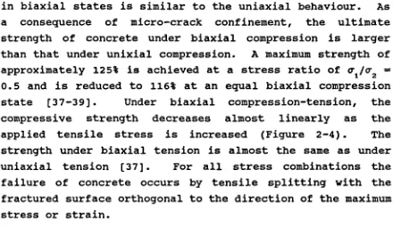
in biaxial states is similar to the uniaxial behaviour. As a consequence of micro-crack confinement, the ultimate strength of concrete under biaxial compression is larger than that under unixial compression. A maximum strength of approximately 125% is achieved at a stress ratio of O1/O2 0.5 and is reduced to 116% at an equal biaxial compression state (37-39]. Under biaxial compression-tension, the compressive strength decreases almost linearly as the applied tensile stress is increased (Figure 2-4). The strength under biaxial tension is almost the same as under uniaxial tension (37]. For all stress combinations the failure of concrete occurs by tensile splitting with the fractured surface orthogonal to the direction of the maximum stress or strain.
The ductility of concrete under biaxial stresses also differs depending on whether the stress states are compressive or tensile as shown in Figure 2-3. The maximum compressive strain under uniaxial and biaxial compression is about 2-3x10 3 rn/rn. The maximum tensile strains for biaxial
compression range between 2x10 3 rn/rn to 4x10 3 rn/rn, which is
greater than under uniaxial compression. In biaxial tension the maximum principal tensile strain is lower than 10 rn/rn and in the confined states of stress both the maximum principal compressive and tensile strains decrease as the tensile stress increases.
[image:46.595.75.515.80.335.2]follows:
1. Classical failure theories such as von Mises, Mohr-Coulomb and Drucker-Prager, are crude approximations of the concrete failure envelope and they can represent only limited regions of total stress space.
2. The biaxial degenerations of some criteria proposed for triaxial compression yield unexpected biaxial failure envelopes which deviate from the experimental observations. To simulate the biaxial failure envelope of concrete, some criteria have been proposed in [42, 43] as functions of the first two stress invariants (Ii, J2 ). The correlation between these criteria and experimental data were found to be quite good.
(iii) Triaxial loading
Several studies on the behaviour of concrete under triaxial stress state have been reported [32, 44-47]. However, test results are less complete and less reliable than uniaxial or even biaxial data. A large dispersion of experimental results has also been observed. Two principal factors are responsible for this scatter (40]. Variation of the materials tested, and variation in the test methods.
Figure 2-5(a) shows typical stress-strain curves from tests by Richard et al [40] which were conducted at a low or moderate confining stress state. Some main conclusions are:
1. The axial strength increases with increasing confining pressure.
2. The high strength is always accompanied by a large deformation. Axial strains over 0.06 were registered at ultimate load (the uniaxial values are usually around 0.002).
4. The unloading at the beginning is parallel to the initial tangent, later declining from the tangent as a result of the stiffness degradation of concrete under high hydrostatic compression.
Experimental studies [45) have indicated that the three-dimensional strength envelope for concrete can be defined in terms of the three stress invariants. The characteristics of concrete failure surface under triaxial stress have been studied in [21, 24, 28, 45). Several failure theories have been proposed to capture these features. The most commonly used failure criteria are the five parameter model of William-Warnke [48] and the four
parameter criterion proposed in [49].
2.2.3 MECHANICAL PROPERTIES UNDER DYNAMIC LOADING CONDITIONS
It has been mentioned in Section 2.2.1 that the material behaviour of concrete under dynamic loading conditions can be significantly different from that under static conditions. Although numerous experimental works for plain concrete under dynamic loading have been reported, most available data are obtained from uniaxial tests. Extensive reviews of such tests have been given in [7, 8].
than concrete with a higher static strength. Another conclusion from these tests is that the strain rate has little or no effect (12, 50] on the initial tangent modulus, but results in an increase in the secant modulus. Generally, it has been also observed that the nonlinearity of the stress strain curves decrease with the increase of strain rate. In tension [12, 31] these curves are almost linear and show only curvature in the final phase of loading. As the nonlinearity of the constitutive diagrams has been associated with micro-cracking, it can be surmised that increase in the strain rate results in a decrease in the amount of micro-cracking. In some tests (19] when the strain rate was increased, the value of the concrete strain at maximum compressive stress increased while in some other tests (18) it decreased. On the basis of the least squares curve fitting to the experimental data, it has been found
[20] that increasing the strain rate from the static value of 10 sec to values as high as 10_i sec results in reduced values of strain at maximum compressive stress. At strain rates higher than 10 seci, however, the compressive peak strain becomes larger than the static value. As contrasted with dynamic compressive tests, the influence of the strain rate upon the tensile cracking strain of concrete has been a lesser subject of research. However, recent experimental studies [12, 31) have indicated that increasing the strain rate results in increased values of the cracking strain in a similar fashion to the observed rate sensitivity of concrete tensile strength.
Biaxial or triaxial testing under dynamic loading is extremely difficult and only Nelissen (51] has conducted biaxial tests at different states of straining. The tests were performed at strain rates of 3.3x10 3 to 1.7x10' sec. The influence of strain rate has been found to be different for different stress ratios.
Research test specimens often have dimensions which require microscopic modelling to idealize concrete components as separate units. However, concrete structures have such dimensions that a constitutive modelling on the macroscopic level is necessary. The present research is concerned with macroscopic numerical models. During the last two decades, several approaches, based on experimental data have been developed for simulating the complicated behaviour of concrete under various stress states and loading conditions. A brief review of these models, which are only based on continuum-mechanics approach, is given below. An extensive review on this topic can be found elsewhere (21, 28].
2.3.1 ELASTICITY BASED MODELS
Early constitutive models were based on linear elasticity to represent concrete behaviour where cracking is the most important factor of nonlinearity [6, 52]. The stress-strain relationship is linear almost up to peak load. However, the linear elasticity based model proved , to be a good approximation of the concrete behaviour only in the tensile loading environment.
According to the Hookean formulation, the nonlinear elasticity based models can be grouped into two types: finite material characterization in the form of secant formulation (termed as hyperelastic model) and incremental model in the form of tangential stress-strain relation (or hypoelastic model).
(i) Hyperelastic model
This is based on the assumption of the existence of a strain energy density function, W (c), such that (28)
ow
£ (2-1)
Oc
experimental data, the shape of the function W can be determined. However, this class of formulation is not popular for concrete modelling since the material model constants do not usually have physical interpretations. From the results of an extensive biaxial stress testing series, Kupfer et al [53] developed a unique relationship between octahedral stress and strain, and the secant bulk and shear moduli.
The behaviour of the hyperelastic model is reversible and path independent. It can model many of the concrete
characteristics such as nonlinearity, dilatation and strain or stress induced anisotropy, but is incapable of describing history dependence, strain softening and rate effects.
(ii) Hvoe1astic model
The material behaviour is described in terms of the stress and strain increments as
= S(a) dc
(2-2)
where the variable tangent stiffness, S, is a function of the current state of stress (or strain). This constitutive model is history dependent and satisfies the reversibility condition only in the infinitesimal sense. In the form of
(2-2) the model exhibits stress-induced anisotropy and the tangent stiffnesses are identical in loading and unloading. For concrete, Coon et al [54] obtained reasonable agreement with uniaxial and biaxial test results by using S as a
linear function of
a.
derived. Following a similar concept, Ottosen [57] proposed a more general form of triaxial coristitutive relation based on variable secant moduli where a sophisticated failure surface [49] is used as a limiting surface. Generally, the variable moduli models provide a good fit to the available test data but the accuracy is increasingly lost as failure or softening regime approaches. Another approach to constructing hypoelastic models is based on an orthotropic assumption [58]. These models are based on the equivalent uniaxial stress-strain relation so the elasticity moduli E1 and E are taken as functions of the state of stress and strain in each of the principal stress directions. These models were extended by Darwin [54] and Elwi [60] to represent concrete under cyclic load. An objection has been made (61] to orthotropic models since the requirement that the principal stress axes coincide with principal strain axes does not hold for concrete under general loading.
The effects of strain rate have been incorporated by Pal [62] in an isotropic hypoelastic model which assumed that the expansion of the failure surfaces depends on the strain rate effect. In general, nonlinear elasticity models are simple to use. However, their applicability is restricted to stress conditions which lie inside the range covered by the material testing data used to determine the material functions.
2.3.2 VISCOELASTICITY BASED MODELS
In the classical form of linear viscoelasticity, the stress at a given instant depends not only on the current strain but also on the previous strain history. Such a constitutive law can be expressed using the hereditary integral as [28]
a (t) =
stress. As the evaluation of this integral requires the record of the previous strain history, it is customary to approximate the relaxation tensor by an exponential series
(Dirichiet Series) (50) of the form
R (t, t") = V R (t') e_(t_t'ti (2-4) L
1=1
where are discrete relaxation times and N is the nwnber of elements in series, Combining equations (2-3) and (2-4) one can obtain
u (t) = 0 + (t) (2-5)
where can be obtained from
1
(2-6) (t) = R 1 (t) (t) -
--These equations correspond to a generalized Maxwell chain model with age dependent stiffness R 1 and viscosities t 1 R1. In contrast to the heredity integral, only current strain rates and stresses are needed if a forward Euler difference formula is utilized to obtain the stresses [28].
Pozzo (63] has reported the results on a study conducted on the applicability of this theory for predicting the dynamic behaviour of concrete using a 3-parameter model (2 elastic element and a viscous Newtonian damper). However, he pointed out that the dissipative mechanism of concrete is not solely of a viscoelastic nature but was prevalently solid-friction type.
peak stress were accounted for by introducing
functions
for their strain rate dependence. Considering concrete to be linearly viscoelastic they also obtained an expression for the variation of the initial modulus with strain rate. However, most of the results presented in the literatureindicate that the initial tangent modulus is strain rate insensitive (12, 50].
The main drawback of linear viscoelasticity is that a rheology based model with a broad relaxation spectrum demands excessive programming, computer storage and material parameters [28, 50].
2.3.3 PLASTICITY BASED MODELS
The classical theory of plasticity is well founded on a physical and mathematical basis with a long history of successful applications involving metals. For compressive loading, concrete initially exhibits almost linear behaviour up to the elastic limit, after which the material is progressively weakened by internal microcracking up to failure. The nonlinear deformations are basically plastic since, upon unloading, only the elastic strain portion can be recovered from the total deformation. This has resulted in using extensively, in recent years, the plasticity approach to describe the nonlinear behaviour of concrete
(67). One criticism of the application of this concept to concrete is that the inelastic behaviour predicted by a plasticity theory is not accompanied by the degradation of elastic moduli, i.e. the decrease of the unloading stiffness. However, this is not significant in the prefailure regime. Besides, the theoretical background of work-hardening plasticity has been quite consolidated.
begins. A hardening rule regulates the evolution of the subsequent loading surfaces during the course of plastic flow. A flow rule defines an incremental plastic stress-strain relationship using a plastic potential function. The application of the theory to concrete requires considerable modifications of the shape of the yield surface, the hardening rule and the flow rule. Most of the research has in the past been made towards defining a suitable failure surface. The initial yield surface is usually assumed to have the same shape as the failure surface but with a reduced size.
The loading surface which is dependent upon the current state of stress a and a number of hardening parameters H1 can be expressed [28] as
F (a, H 1 ) = 0 i = 1, 2, ... (2-7) Equation (2-7) represents an envelope of stress state in the material which causes the onset of plastic behaviour. Each
stress point inside the surface represents an elastic state of stress and each point on it a plastic state. Due to the hardening parameters, H 1 , the loading surface can translate and change its shape until the failure surface is reached. The failure surfaces which are widely used in the numerical analyses of concrete structures include classical failure criteria and failure theories based on a biaxial or triaxial
testing data. Detailed reviews of the failure theories proposed in the last two decades are given in (21, 28).
A perfectly plastic body is defined by the yield criterion which depends only on the stress tensor, F (a) = 0. During plastic deformation this criterion remains unaltered. The simplest hardening rule is isotropic hardening where the yield surface expands uniformly as
F (a, A) = 0 (2-8)
![Figure 2.4 Biaxial strength of concrete [37]](https://thumb-us.123doks.com/thumbv2/123dok_us/1695713.122961/79.595.119.483.123.659/figure-biaxial-strength-of-concrete.webp)
![Figure 2.5 Concrete behaviour under triaxial stress [45]](https://thumb-us.123doks.com/thumbv2/123dok_us/1695713.122961/80.595.149.397.149.539/figure-concrete-behaviour-under-triaxial-stress.webp)
![Figure 2.7Stress-strain diagrams for tso steel speci.rrens atdifferent rates of straining [28]](https://thumb-us.123doks.com/thumbv2/123dok_us/1695713.122961/81.595.138.346.126.359/figure-stress-strain-diagrams-steel-speci-atdifferent-straining.webp)
![Figure 3.5 Energy-scaled impulse versus energy-scaledradius for deflagration explosions [115]](https://thumb-us.123doks.com/thumbv2/123dok_us/1695713.122961/126.595.161.361.71.326/figure-energy-scaled-impulse-versus-scaledradius-deflagration-explosions.webp)
![Figure 3.9 Pressure-time trace for a typical internaldeflagrative explosion [116]](https://thumb-us.123doks.com/thumbv2/123dok_us/1695713.122961/129.595.124.427.213.430/figure-pressure-time-trace-for-typical-internaldeflagrative-explosion.webp)