A New Class of Parallel Data Convolutional Codes
Wei Xiang and Steven S. Pietrobon
Abstract— We propose a new class of parallel data convolu tional codes (PDCCs) in this paper. The PDCC encoders inputs are composed of an original block of data and its interleaved ver sion. A novel single selfiterative softin/softout a posteriori prob ability (APP) decoder structure is proposed for the decoding of the PDCCs. Simulation results are presented to compare the per formance of PDCCs to that of parallel concatenated convolutional codes (PCCCs).
Index Terms—PDCCs, Selfiterative, APP.
I. INTRODUCTION
The original turbo codes proposed by Berrou et al. [1] are binary turbo codes in that those codes accept only single binary inputs. The socalled nonbinary turbo codes are based on a parallel concatenation of RSC component codes withminputs (m�2) [2]. The advantages of nonbinary turbo codes include better convergence in iterative decoding, large minimum dis tances, less sensitivity to puncturing patterns and suboptimum decoding algorithms and reduced latency [2]. Doublebinary turbo codes [3] (m= 2) usually possess better errorcorrecting capabilities than binary turbo codes for equivalent implementa tion complexity and coding rate. This observation led to the use of circular recursive systematic convolutional (CRSC) codes by Berrou et. al. [4]. CRSC codes have the advantage of a grace ful degradation to increasing coding rate, and is less suscepti ble to puncturing and suboptimal decoding algorithms [5]. As a consequence, a CRSC code was chosen for the DVBRCS standard for return channel via satellite [6] as an alternative to concatenated ReedSolomon (RS) and nonsystematic convolu tional codes due to their outstanding performance.
Inspired by a paper submitted recently to Electronic Let
ters [7], we propose a new class of parallel data convolutional codes (PDCCs) in this paper. The PDCC encoder inputs are composed of an original block of data and its interleaved ver sion. A novel single selfiterative softin/softout a posteriori probability (APP) decoder structure is proposed for the decod ing of the PDCCs.
The remainder of this paper is organised as follows. Sec tionIIAbriefly reviews the circular recursive systematic con volutional code adopted in the DVBRCS standard. A new class of parallel convolutional codes is proposed in SectionIIB. Sec tionIIIdiscusses the MAP decoding and selfiterative decoding of PDCCs. SectionIVis dedicated to simulation results. The concluding remarks are presented in SectionV.
II. PARALLELDATACONVOLUTIONALCODES
A. Circular Recursive Systematic Convolutional Codes
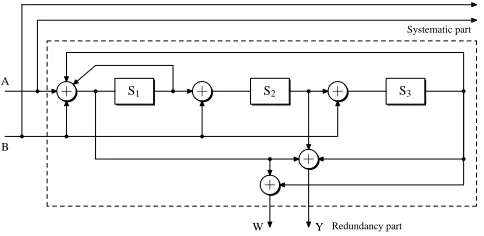
Fig.1depicts the CRSC code adopted in the DVBRCS stan dard [6]. The data sequence to be encoded consists of a block ofN bits grouped intoM couples (N = 2M). The incoming data is first demultiplexed and fed intoA andB of a CRSC encoder (the first bit to A, second bit to B and so on). A
andBare two systematic bits, whereasY andW are two par ity bits. Since a CRSC encoder has two inputs and four out puts, it can provide an ample set of seven coding rates, i.e.,
R = 1/3,2/5,1/2,2/3,3/4,4/5 and 6/7. These rates are achievable through puncturing the parity bits.
We show the derivation of the parity check equations and its canonical form for the CRSC code adopted by the DVBRCS standard as shown in Fig.1.
+ S1 + S2
+ +
+ S3
A
B
W Y Redundancy part
Systematic part
Fig. 1. CRSC component code structure.
Through some mathematic derivation, it is not difficult to show that the parity check equations of the parity output bits
Y andW are expressed by (1) and (2) as follows:
(1 +D2+D3)A+ (1 +D+D2+D3)B
+ (1 +D+D3)Y = 0 (1)
(1 +D3)A+ (1 +D2)B+ (1 +D+D3)W = 0. (2)
Furthermore, the canonical form [8] of the CRSC depicted in Fig.1can be derived, which is illustrated in Fig.2. Refer to [9] for detailed derivation of the canonical form shown in Fig.2.
B. Parallel Data Convolutional Codes
we propose a new class of parallel data convolutional codes. Fig. 3 depicts a PDCC encoder in its canonical form which adopts the CRSC code described in SectionIIA as the con stituent convolution code. It is assumed that S� is the MSB
1
(most significant bit) andS� = 4S� + 2S� +S
3.
1 2 �
[image:1.612.311.553.338.456.2]A
+ + S1�
+
+ S�
2
+
+ S3� +
X
B X�
Y
W
Fig. 2. Canonical systematic convolutional code of coding rate 1/2.
A
+ + S�
1
+
+ S�
2
+
+ S�
3 + π A�
X
X�
Y
W
Fig. 3. PDCC encoder.
data inputs is the reason that we name it parallel data convolu tional codes.XandX�are two systematic outputs, whereasY
andW are two parity bits. The parity check relationships ofY
andW resembling (1) and (2) are given by
(1 +D2+D3)A+ (1 +D+D2+D3)A�
+ (1 +D+D3)Y = 0 (3)
(1 +D3)A+ (1 +D2)A�+ (1 +D+D3)W = 0. (4)
The data streamAand its interleaved versionA�are fed into the decoder at the same time. However,A�is decorrelated rela tive toAdue to the presence of the interleaver. For a reasonably good interleaver, like theSinterleaver used in our simulations, this should not adversely affect the performance of the code. The systematic bitX�is not transmitted asX�is the interleaved version ofX. Thus, the PDCC encoder shown in Fig.3can typ ically provide a code rate of1/2by transmitting the systematic bitX and the parity bitY, and a code rate of1/3by transmit ting the systematic bitX and the parity bitsY andW. It can also provide other coding rates through puncturing the parity bitsY andWif needed.
It is noted that the idea of selfconcatenation in [10] is dif ferent from that of PDCCs. For the idea of selfconcatenation, dataX and its interleaved versionX� are joined together and encoded as a single data stream. In other words, the end state ofX is the starting state ofX�. However, this is quite differ ent from the idea of PDCCs whereX andX� are fed into the decoder at the same time.
III. SELFITERATIVEDECODING OFPDCCS
A. MAP Decoding of PDCCs
The key difference between the MAP algorithm for PDCCs and the MAP algorithm presented in [11] is that the PDCC en coder has two input bits and four output bits, including two systematic bitsA, A� and two parity bitsY, W. The MAP al gorithm described in [11], however, is applicable to the soft
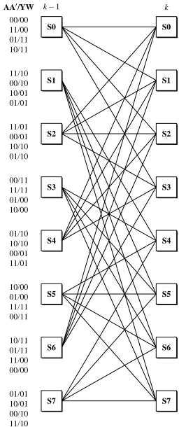
decoding of rate 1/2 systematic convolution codes which have one input bit and two output bits, including one systematic bit and one parity bit. Fig.4illustrates the trellis diagram of the PDCC presented in Fig.3. It is an 8state trellis. The numbers shown on the left of each state represent a format of system atic bits/parity bits, i.e.,AA�/Y W. The numbers from top to bottom correspond to the state transitions diverging from each state from top to bottom.
AA�/YW k−1
k 00/00
11/00 01/11 10/11
11/10 00/10 10/01 01/01
11/01 00/01 10/10 01/10
00/11 11/11 01/00 10/00
01/10 10/10 00/01 11/01
10/00 01/00 11/11 00/11
10/11 01/11 11/00 00/00
01/01 10/01 00/10 11/10
S0
S1
S2
S3
S4
S5
S6
S7
S0
S1
S2
S3
S4
S5
S6
S7
Fig. 4. PDCC’s 8state trellis diagram.
Assume that the outputs of the PDCC encoder depicted in Fig.3 at time indexk are the systematic bitAk, and the par
ity bitsYk andWk. These outputs are BPSK modulated and
transmitted through an AWGN channel. At the receiver end, the received symbols at time indexkare defined as
1
RAk = (1−2Ak) +nk (5)
2
RYk = (1−2Yk) +nk (6)
3
RWk = (1−2Wk) +nk, (7)
1 3
with nk, n2k and nk being three independent normally dis tributed Gaussian random variables with varianceσ2. A
k
�, the
interleaved version of the received symbolAk, is obtained by
interleavingAkat the receiver end.
[image:2.612.42.292.52.149.2] [image:2.612.366.494.168.473.2] [image:2.612.40.294.176.278.2]� � � � � � � � � � �� � � �
Sk =mwithAk=i, can be expressed as
j
γi,m ξ
iξ�
1 � �2
= k k exp RAk−(1−2Ak) dRAk k
23√2πσ −2σ2
1 1 � �2
exp RA� −(1−2A�
k k
· √
2πσ −2σ2 k) dRA�
1 1 � �2
exp RYk−(1−2Yk) dRYk
· √
2πσ −2σ2
1 1 � �2
exp RWk−(1−2Wk) dRWk
· √
2πσ −2σ2
j
= χkξkiξk k+RYkYk
�
exp −Lc RAkAk+RA�A
�
k
+RWkWk , (8)
j
whereχkis a constant,ξki =P r(Ak =i),ξk� =P r(A�k =j), Lc = 2/σ2, anddRAk,dRAk�,dRYkanddRWkare differentials
ofRAk,RAk�,RYkandRWk.
The forward state metricαm at timekand statem can be k
shown as
3
= γi,b(i,m)αb(i,m),
αmk k−1 k−1 (9)
i=0
whereb(i, m)denotes the backward state whose next state ism
given inputiat the previous time. Likewise, the backward state metricβmk at timekand statemcan be expressed as
3
= γi,m f(i,m),
βmk k βk+1 (10)
i=0
wheref(i, m)denotes the forward state given current input i
and statem.
The likelihood ratioλkassociated with each decoded bitAk
is defined as
Pr(Ak= 1|RA, RY, RW)
λk =
Pr(Ak= 0|RA, RY, RW) 3
� �αmγi,m f(i,m)
k k βk+1
m i=2
= 1
� �αmγi,m f(i,m)
, (11)
k k βk+1
m i=0
wherei = 0,1,2,3corresponds toA, A� inputs of 00, 01, 10 and 11. Similarly, the loglikelihood ratioλ�k of the interleaved bitA�kcan be written as
Pr(A�k= 1|RA, RY, RW)
λ�k =
Pr(A� = 0|R
A, RY, RW) k
� � αmγi,m f(i,m)
k k βk+1
m i=1,3
=
� �
αmγi,m f(i,m). (12)
k k βk+1
m i=0,2
Decisions on decoded bitsA�kare then made by the PDCC MAP
decoder by comparingλkto a threshold equal to one.
B. Selfiterative Decoding
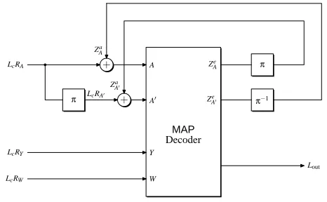
The novelty of decoding the PDCCs lies in selfiterative de coding. The selfiterative PDCC decoder operates like a normal MAP decoder except it feeds the extrinsic outputs after inter leaving or deinterleaving back as a priori inputs. Fig.5shows a schematic of a selfiterative PDCC decoder.
LcRA
LcRY
LcRW
π
π
π−1 + + Lout A A� Y W Ze A Ze A� MAP LcRA� Decoder Za A Za A�
Fig. 5. Selfiterative PDCC decoder.
The inputs to the decoder are the soft outputs of a noisy channelLcRA,LcRY andLcRW, respectively. The decoder
reconstructsLcRAby interleavingLcRA. The idea of the self
iterative decoding comes from the fact that R�A is the inter leaved version ofRA, so that the extrinsic information ofRA
can be fed back as the a priori information forR�Aafter inter leaving and the extrinsic information ofR�Acan be fed back as the a priori information forRAafter deinterleaving.
We denote the a priori information ofRAandRA� byZAa and Za
A�, while the extrinsic information ofRAandR�Aare denoted
byZe andZe
A�, respectively. The selfiterative MAP decoder A
computes the APP of the information bitA. The LLR output of the decoder can be expressed as
Lout=LcRA+LcRA�+ZAa +ZAe +ZAa� +ZAe�. (13)
The selfiterative PDCC decoder proceeds as follows. At the first decoding iteration,ZAa andZAa�are initialised to zero. For the subsequent iterations,ZAe is interleaved and fed back as the
a priori information forA�, i.e.,ZAa� =π(ZAe)whereπ(·)de notes an interleaving mapping. Likewise,ZAe� is deinterleaved and fed back as the a priori information for A, i.e., Za =
A π−1(Ze
A�)whereπ−1(·)denotes a deinterleaving mapping. At
the final iteration, the decoder delivers the loglikelihood out put Lout. The selfiterative decoding process can be clearly
seen from the two feed back connections betweenZe andZa
A A�,
andZe andZa
Ain Fig.5. A�
IV. SIMULATIONRESULTS
In this section, we compare the performance of the proposed PDCC to a parallel concatenated CRSC coding system used in the DVBRCS standard and present simulation results. The sys tem functional block diagram is graphically shown in Fig.6.
The horizontal and vertical constituent codes used in Fig.6
[image:3.612.314.547.137.281.2]π
ENC−
ENC|
A
B
Y
A�
B�
W
Fig. 6. Parallel concatenated CRSC encoder.
grouped into M couples (N = 2M). The horizontal con stituent encoder is fed with the information bits in the natu ral order of the data, whereas the vertical constituent encoder is fed with the same information bits in an interleaved order of the data. A� andB� bits are not transmitted since they can be reconstructed by interleaving the A and B bits at the re ceiver side. The parallel concatenated CRSC encoder can pro vide seven code rates as defined in the DVBRCS standard, i.e.,
R = 1/3, 2/5, 1/2, 2/3, 3/4, 4/5, 6/7 [6]. The decoder structure is similar to that of turbo codes [1] except that the MAP decoders for a rate 1/2 systematic convolutional code are replaced by the MAP decoders for the CRSC described in Sec tionIIA.
Simulations were conducted to compare the performance for the proposed PDCC system shown in Fig.3to the parallel con catenated CRSC system shown in Fig.6. The simulation con figurations are as follows. AnStype interleaver [12] is adopted withS equal to 47. Randomly generated data of length 8K
(8192) bits is used for both systems. The channel coding rate for both systems is 1/2. Simulation results are presented in Fig.7, where the PCCC curve refers to the performance of the parallel concatenated CRSC system.
As depicted in the figure, the performance of the PDCC is very close to that of the parallel concatenated CRSC at low
Eb/N0up to 0.6 dB. However, PDCC performs at least 0.2 dB
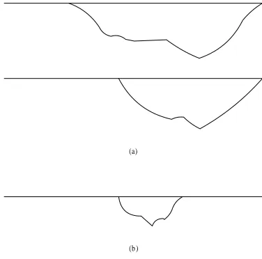
worse than the parallel concatenated CRSC at low BERs. We conjecture the relatively poor performance of PDCCs at low BER may be due to the selfterminating phenomena with one input bit. Fig.8illustrates the trellis terminating properties of the PCCCs (turbo codes) and PDCCs. For the PCCCs, an error bit could cause the trellis path to divert from the two allzero paths as shown in Fig.8–(a). The same bit is interleaved and fed into the second encoder. That bit would not cause the di verted trellis path to reemerge earlier. On the other hand, for the PDCCs, an error causes a diversion from the allzero trellis path. The same bit is interleaved and then fed into the same PDCC encoder. That bit could cause an earlier trellis remerge as shown in Fig.8–(b). The decoding complexity of PDCCs is similar to that of the PCCCs. This is because the PDCC de coder consists of one constituent MAP decoder which decodes one bit in each iteration, whereas the PCCC decoder consists of
0 0.2 0.4 0.6 0.8 1 1.2 1.4 1.6 1.8 2 10−7
10−6
10−5
10−4
10−3
10−2 10−1
100
Eb/N0 (dB)
Bit Error Rate (BER)
PDCC: 8 iterations PDCC: 16 iterations
PDCC: 8 iterations + trellis termination PDCC: 16 iterations + trellis termination PCCC: 8 iterations
Fig. 7. Simulation results.
two constituent MAP decoders which decode two bits in each iteration.
(a)
(b )
Fig. 8. Selfterminating property of (a) PCCC; (b) PDCC.
A way of overcoming the selfterminating property may be by designing the interleaver so as to avoid selfterminations. For example, if Ak = 1, with zeros elsewhere except at A�k+3 = 1, then we would have a selfterminating sequence going through statesS0�S3 �S4 �S0. Thus, we could de sign the trellis such that if the interleaver maps positionitoj, then(i−j)mod 3 is not equal to zero. This will remove many selfterminating sequences and hopefully lower the error floor. Another possibility is designing the convolutional code so that these period 3 terminations do not occur. It may be possible to increase the selftermination length to2ν−1 = 7, which is the
maximum that can be expected with a primitive divisor polyno mial. These longer lengths should be easier to design out of the interleaver.
[image:4.612.98.243.51.210.2] [image:4.612.308.555.65.262.2] [image:4.612.335.523.339.525.2]the two trellises of a spacetime code into a super trellis. Subse quently, selfiterative decoding could be applied to such a trellis with non modulo2 operation.
V. CONCLUSIONS
In this paper, a new class of parallel data convolutional codes is presented. The PDCC encoder takes two parallel data inputs, with one being the original data and the other being the inter leaved data. The PDCC decoder has an innovative selfiterative decoding structure. Unlike a turbo decoder where the extrinsic output of one MAP decoder is passed on to the other as the a
priori input, the PDCC decoder operates like a normal MAP de
coder but feeds the extrinsic outputs back as its own interleaved
a priori inputs.
The performance of PDCCs was compared to that of a paral lel concatenated CRSC, equivalent to the one used in the DVB RCS standard. The two schemes performed close to each other at low SNRs, however the parallel concatenated CRSC outper formed PDCCs by at least 0.2 dB at low BERs. Also, the PDCC has a higher error floor than the PCCC. We conjecture this is due to the selfterminating property of PDCCs with single bit errors. Although the performance of PDCCs is not encourag ing, the idea of selfiterative decoding is worth exploring and can be applied to some codes like spacetime codes.
REFERENCES
[1] C. Berrou, A. Glavieux, and P. Thitimajshima, “Near Shannon limit error correcting coding and decoding: turbocodes,” in Proc. IEEE Int. Conf. Commun. (ICC’93), Geneva, Switzerland, May 1993, pp. 1064–1070. [2] C. Berror, M. J´ez´equel, C. Douillard, and S. Kerou´edan, “The advantages
of nonbinary turbo codes,” in Proc. IEEE Information Theory Workshop (ITW’01), Cairns, Australia, Sept. 2001, pp. 61–63.
[3] C. Berrou and M. Jezequel, “Nonbinary convolutional codes for turbo coding,” Electron. Lett., vol. 35, no. 1, pp. 39–40, Jan. 1999.
[4] C. Berrou, C. Douillard, and M. Jezequel, “Multiple parallel concate nation of circular recursive convolutional (CRSC) codes,” Annals of Telecommunications, vol. 54, no. 34, pp. 166–172, Mar.Apr. 1999. [5] M. R. Soleymani, Y. Gao, and U. Vilaipornsawai, Turbo Coding for Satel
lite and Wireless Communications. Norwell, MA: Kluwer Academic Publishers, 2002.
[6] ETSI EN 301 790, Digital Video Broadcasting (DVB); Interaction chan nel for satellite distribution systems. ETSI reference EN 301 790, v.1.3.1, Mar. 2003.
[7] Y.H. Li and D. Li, “Twodimensional logMAP decoding algorithm and its applications,” Submitted to Electron. Lett., Mar. 2003.
[8] G. D. Forney, “Convolutional codes I: Algebraic structure,” IEEE Trans. Inform. Theory, vol. IT16, pp. 720–738, Nov. 1970.
[9] W. Xiang, “Joint sourcechannel coding for image transmission and re lated topics,” Ph.D. dissertation, University of South Australia, Adelaide, Australia, 2003.
[10] C. Berrou, “Some clinical aspects of turbo codes,” in Proc. Int. Symp. on Turbo Codes & Related Topics, Brest, France, Sept. 1997, pp. 26–31. [11] S. S. Pietrobon, “Implementation and performance of a Turbo/MAP de
coder,” Int. J. Satellite Commun., vol. 16, pp. 23–46, Jan.Feb. 1998. [12] D. Divsalar and F. Pollara, “Multiple turbo codes for deepspace com