A COMPARATIVE STUDY OF RATE OF RETRACTION AND
MOLAR CONTROL BETWEEN DUAL DIMENSIONAL WIRES
AND RECTANGULAR WIRES DURING RETRACTION,
USING MINISCREWS
Dissertation Submitted to
THE TAMILNADU DR. M. G.R. MEDICAL
UNIVERSITY
For partial fulfillment of the requirements for the degree of
MASTER OF DENTAL SUR GERY
BRANCH – V
ORTHODONTICS AND DENTOFACIAL ORTHOPAEDICS
THE TAMILNADU DR. M.G.R MEDICAL UNIVERSITY
CHENNAI – 600 032
ACKNOWLEDGEMENT
First of all, I seek the blessings of the Almighty God without whose benevolence; the study would not have been possible.
I take this opportunity to thank my parents Mrs.Padmini and Mr.Gnanesh, my Husband Dr.Nagesh D.M.,and my adorable kids Mas.Ruhann and Mas.ryann for their endless patience during the entire period of this three years of course.
It is my privilege and great honour to express my gratitude to my respected guide and Principal Dr. SRIDHAR PREMKUMAR, M.D.S., Professor,Department of Orthodontics and Dentofacial Orthopaedics, Tamilnadu Govt.Dental College and Hospital, Chennai-3, for his conceptualization,patience guidance, support and encouragement throughout the study and during the three years of course.
I express my deep sense of gratitude and honour to my respected
Professor and Head, Dr. G.Vimala M.D.S., Department of Orthodontics and Dentofacial Orthopaedics, Tamilnadu Govt. Dental College and Hospital, Chennai-3, for her constant inspiration and encouragement throughout the entire course.
I owe my thanks to Dr.Balashanmugam,M.D.S.,Professor, Department of Orthodontics and Dentofacial Orthopaedics, Tamilnadu Govt. Dental College and Hospital, Chennai-3, for helping me with his valuable suggestions and encouragement.
I thank Dr.Mohammad Junaid., for helping me with the Statistics in the study.
I offer my gratitude to my patients who expressed complete cooperation for the successful completion of this study
TRIPARTITE AGREEMENT
This agreement herein after the “Agreement” is entered into on this
day... day of December 2014 between the Tamil Nadu Government Dental College and Hospital represented by its Principal having address at Tamilnadu Government Dental college and Hospital, Chennai-03, (hereafter referred to as the ‘college’
And
Dr.SRIDHAR PREMKUMAR aged 47 years working as professor in the Department of Orthodontics and Dentofacial orthopaedics, at the college, having residence address at B-3, Block 2, Jains Ashraya Phase III, Arcot road,Virugambakkam, Chennai-92. (herein after referred to as the ‘Principal investigator’)
And
Dr.Sangeetha.M.G.aged 36 years currently studying M.D.S (Orthodontics) in Tamilnadu Government Dental college and Hospital (herein after referred to as the ‘PG/Research student and co- investigator’).
Whereas the ‘PG/Research student as part of his curriculum undertakes to
1. The parties agree that all the Research material and ownership therein shall become the vested right of the college, including in particular all the copyright in the literature including the study, research and all other related papers.
2. To the extent that the college has legal right to do go, shall grant to licence or assign the copyright do vested with it for medical and/or commercial usage of interested persons/entities subject to a reasonable terms/conditions including royalty as deemed by the college.
3. The royalty so received by the college shall be divided equally by all the parties.
4. The PG/Research student and PG/Principal Investigator shall under no circumstances deal with the copyright, Confidential information and know how generated during the course of research/study in any manner whatsoever, while shall sole vest with the manner whatsoever and for any purpose without the express written consent of the college.
5. All expenses pertaining to the research shall be decided upon by the principal investigator/Co-investigator or borne sole by the PG/research student(co-investigator).
6. The college shall provide all infrastructure and access facilities within and in other institutes to the extent possible. This includes patient interactions, introductory letters, recommendation letters and such other acts required in this regard.
7. The principal investigator shall suitably guide the student Research right from selection of the Research Topic and Area till its completion. However the selection and conduct of research, topic and area research by the student researcher under guidance from the principal investigator shall be subject to the prior approval, recommendations and comments of the Ethical Committee of the college constituted for this purpose.
9. If any dispute arises as to the matters related or connected to this agreement herein, it shall be referred to arbitration in accordance with the provisions of the Arbitration and Conciliation Act, 1996.
10. In witness whereof the parties hereinabove mentioned have on this the day month and year herein above mentioned set their hands to this agreement in the presence of the following two witnesses.
College represented by its
Principal PG Student
Witnesses Student Guide
ABSTRACT
Introduction: Conventional rectangular wires used for retraction of anteriors in
premolar extraction cases, causes increased resistance to sliding due to various
factors like stiffness friction, binding etc., thereby increases the treatment time and
also puts a strain on the molars due to the reciprocating forces of retraction. Dual
Dimensional wire has been used in this study to reduce the resistance and allow
easy sliding of the archwire during retraction, along with good control of molars
with the help of miniscrews as direct anchorage.
Aim and Objectives: To study the rate of space closure and molar control
between Dual Dimensional wire and Rectangular wire during retraction using
miniscrews. To compare the rate of space closure and molar control between the
above two wires.
Materials and Methods: Sixteen patients, chosen in the age group of 17-25,who
fulfilled the inclusion and exclusion criteria were segregated as Group A and B,
for Dual Dimensional wire and conventional Rectangular wire respectively.
Models, Cephalograms were taken before and after the study period (4
months).Clinical procedure involved placing the microimplants and the wires in
the respective groups followed by retraction with NiTi coil springs, attached
between the implant head and S hook fixed mesial to canine. At the end of study
period, results were analysed using SPSS software .
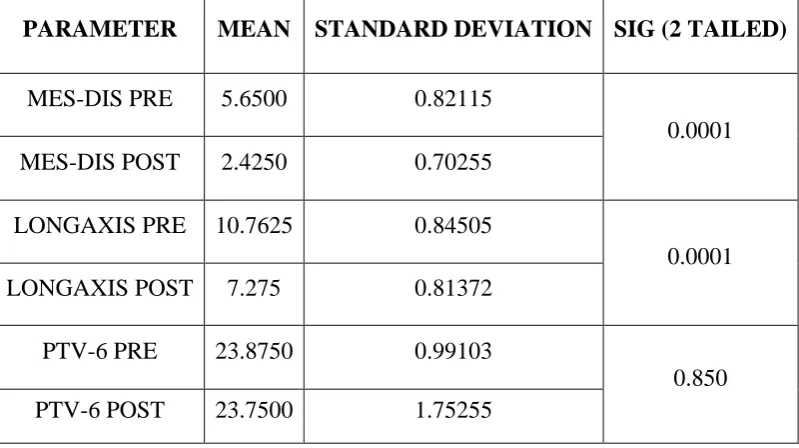
Results: The results showed significant difference in the amount of space closure
DDW group, in the given study period. The mean change in the amount of space
closure was 4.01mm and 3.31 mm in DDW and Rectangular wire group
respectively. Mesial tangent on the right molars showed marginal significance
(0.049). Minor changes were observed in the position of molars in both the groups
with more changes in the Rectangular wire, though the changes were statistically
insignificant.
Conclusion: In the era of low friction systems and Microimplant, it becomes
prudent to choose Dual Dimensional wire over conventional wire for smooth and
easy sliding of archwire during retraction, when miniscrews act as anchorage
provider, to control the molars, and hence faster tooth movement leading to
reduced retraction time for space closure, in orthodontic treatments.
Keywords: Dual Dimensional wire, rectangular wire, NiTi coil spring,
CONTENTS
S.NO. TITLE PAGE NO.
1. INTRODUCTION 1
2. AIMS AND OBJECTIVES 4
3. REVIEW OF LITERATURE 5
4. MATERIALS AND METHODS 29
5. RESULTS 38
6. DISCUSSION 64
7. SUMMARY AND CONCLUSION 74
8. BIBLIOGRAPHY I
LIST OF TABLES
1 Descriptive Study -Group A Pre Treatment Cephalometric Measurement
1 A Descriptive Study -Group A Posttreatment Cephalometric Measurement
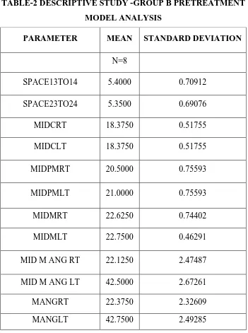
2 Descriptive Study -Group B Pretreatment Model Analysis Measurements
2A Descriptive Study Group B Posttreatment Model Analysis Measurements
3 Descriptive Study -Group B Pretreatment Cephalometric Analysis Measurements
3A Descriptive Study -Group B Post Treatment Cephalometric Analysis Measurements
4 Descriptive Study -Group B Pretreatment Model Analysis Measurements
4A Descriptive Study -Group B Posttreatment Model Analysis Measurements
5 Intra Group Comparision Of PrePost Treatment Values Group A -cephalometric measurements –space closure and molar position
6 Intra Group Comparision Of PrePost Treatment Values Group A -Cephalometric Measurements – Molar Position
7 Intra Group Comparision Of Group A Model Analysis –For Space Closure
8 Intra Group Comparision Of Group A - Model Analysis -Tranverse Control
9 Intra Group Comparision Of Group A -Model Analysis –-Rotational Control
10. Intra Group Comparision Of Group B (Intra Group)-Cephalometric Measurements - Space Closure and Molar Position
11 Intra Group Comparision Of Group B Cephalometric Measurements- Rotational Control
12 12 Intra Group Comparision Of Group B -Model Analysis –For Space Closure
14 Intra Group Comparision Of Group B- Model Analysis –Angular Measurement Of 1st Molar With Respect To Midline. Rotational Control
15 Difference Calculation -Group A Vs Group B-Cephalometric Measurements
16 Difference Calculation -Group A Vs Group B-Cephalometric Measurements –Rotational Control
17 Difference Calculation -Group A Vs Group B -Model Analysis - Space Closure
18
Difference Calculation -Group A Vs Group B -Model Analysis -Linear Measurement Between Midline To Canine,2nd Premolar And 1st Molar-Transverse Control
19 Model Analysis –Angular Measurement Of 1 st
Molar With Respect To Midline-Between The Groups Rotational Control.
20 Model Analysis Group A-Pre-Post Treatment -Incisive Papilla -1 st
Molar,2ndpremolar And Canine -Anteroposterior Control –Left Side.
21 Model Analysis Group A –Pre-Post Treatment -Incisive Papilla -1 st
Molar,2ndpremolar And Canine Anteroposterior Control- Right Side.
22
Model Analysis Group B –Pre-Post Treatment Model Analysis-Incisive Papilla -1st Molar,2ndpremolar And Canine - Anteroposterior Control- Right Side
23 Model Analysis Group B-Pre-Post Treatment -Incisive Papilla -1 st
LIST OF CHARTS
1 Group A Pre-Post Treatment – Cephalometric Analysis
2 Group A Pre-Post Treatment – Cephalometric Analysis
3 Intra Group Comparision Of Group A -Cephalometric Analysis
4 4 Intra Group comparison Of Group A -Model Analysis –Transverse( Linear Measurement Between Midline To Canine,2nd Premolar And 1st Molar )
5 Intra Group Comparision Of GroupA -Model Analysis –Angular Measurement Of 1st Molar With Respect To Midline DISTAL
6 Intra Group Comparision Of GroupA -Model Analysis –Angular Measurement Of 1st Molar With Respect To Midline MESIAL
7 Intra Group Comparison Of GroupB -Model Analysis –For Space Closure
8 Comparison of GroupB within the group (intra group)Model analysis –Angular measurement of 1st molar with respect to midline.DISTAL
9 Comparison of GroupB within the group (intra group)Model analysis –Angular measurement of 1st molar with respect to midline.MESIAL
10 Difference Calculation -Group A Vs Group B-Cephalometric Measurements-Space Closure
11 Difference Calculation -Group A Vs Group B-Cephalometric Measurement-Molar position
12 Difference Calculation -Group A Vs Group B-Angular Changes -Cephalometric Measurements –molar rotation
13 Difference Calculation -Group A Vs Group B -Model Analysis -Horizontal Distance Between Canine And The 2nd Premolar - Space Closure
14 Difference Calculation -Group A Vs Group B -Model Analysis -Linear Measurement Between Midline To Canine,2nd Premolar And 1st Molar
15 Difference Calculation-Model Analysis –Angular Measurement Of 1 st
LIST OF PHOTOPLATES
1 Cephalometric Radiographic Unit2 Implant Kit
3 Archwires Springs,Hooks,Dontrix Gauge
4 Model With Grid
5 Model Analysis
6 X Ray Viewer For Cephalometric Tracing
7 Iopa X Ray-Pre-Post Treatment Group A And Group B
8 Models-Group A -Pretreatment Lateral Views
9. Models-Group A Posttreatment Lateral Views
10. Models-Group B -Pre Treatment – Lateral Views
11. Models-Group B –Post Treatment – Lateral Views
12. Models-Group A -Pre Treatment –Occlusal View
13. Models-Group A –Post Treatment –Occlusal View
14. Models-Group B–Pre Treatment –Occlusal View
15. Models-Group B –Post Treatment –Occlusal View
16. Clinical Pictures Group A-Right And Left ,Lateral And Occlusal View
17. Clinical Pictures Group B-Right And Left Lateral ,And Occlusal View
18. Cephaolmetric Analysis-Group A Pre And Post Treatment
LIST OF ANNEXURES
1.
Information sheet in Tamil2.
Information sheet in English3.
Informed consent form in Tamil4.
Informed consent form in English5.
Informed consent form in Tamil for Radiographicexposure
6.
Informed consent form in English for Radiographicexposure
7.
Ethical committee approval certificateABBREVIATIONS
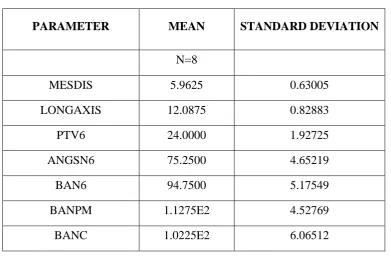
MESDIS Mesiodistal measurement of extraction space in millimeters
LONGAXIS Horizontal distance between the longaxis of 2nd premolar and canine in millimeters
PTV-6- Horizontal distance between pt v to distal of 1st molar in millimeters
ANG SN 6- Angle between sn plane and 1st molar in degrees BA-N6,PM,M Basion-nasion plane to 1st molar,2nd premolar and
canine in degrees
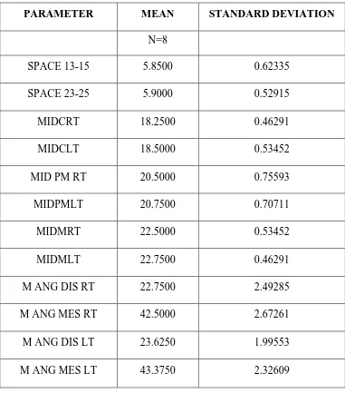
SPACE 13-15 Space present between 13 and 15 in millimeters
SPACE 23-25 Space present between 23 and 25 in millimeters
MID C RT Midline to right canine in millimeters
MID C LT Midline to left canine in millimeters
MID PM RT Midline to right premolar in millimeters
MID PM LT Midline to left premolar in millimeters MID M RT Midline to right molar in millimeters
MID M LT Midline to left molar in millimeters
M ANG DIS RT Midline to right molar distal tangent in degrees
M ANG MES RT Midline to right molar mesial tangent in degrees
M ANG DIS LT Midline to right molar mesial tangent in degrees
M ANG MES LT Midline to right molar distal tangent in degrees
I.P.-6 Anteroposterior distance from incisive papilla to the
reference points drawn from the central pit of 1st
I.P.-5 Anteroposterior distance from incisive papilla to the
reference points drawn from the central pit of 2nd
premolar in millimeters
I.P.-3 Anteroposterior distance from incisive papilla to the reference points drawn from the central pit of canine in millimeters.
I.P. Incisive papilla Perpendicular
IOPA Intra oral periapical radiographs
SPSS Statistical Package for Social Sciences
MIA Mini implant Anchorage
T 0 Pre-treatment
T1 Post-treatment
MBT Mc laughlin Bennet Trevisi
1
INTRODUCTION
The success of any treatment lies in choosing the right materials and
techniques, to bring forth the required changes when preserving the rest of the
environment. It holds true for Orthodontic treatments too. It is preferable to
achieve the required tooth movement with the rest of the teeth or occlusion
unharmed. Of all the treatments done in Orthodontics, retraction of Proclined
anterior teeth forms a very important and common procedure. Retraction can be
simply defined as moving the teeth Posteriorly. It is done mainly by 1.Enmasse or
2. Two stage retraction (separate canine retraction).
Although the two steps procedure is predictable and has excellent fail-safe
characteristics, it takes longer to close space in two steps than one. so, enmasse
retraction is recommended1..To maximize the utility of the extraction space for
retraction of anteriors, in premolar extraction cases it is essential to control the
amount of incisor retraction vs. molar-premolar protraction. Preventing the
posteriors from moving forward into the extraction space (Anchorage control)- is
an essential part of treatment planning in Orthodontics.
The reasons for anchorage loss are excessive force, improper anchorage
preparation, impingement of the roots of the incisors or anterior teeth to the labial
cortical plate etc. The common methods to prevent anchorage loss are by using
anchorage savers like 1. Tranpalatal arches, lingual arches, nance palatal
arches.2.use of optimum force 3.usage of differential force4.reinforcemnt of
2
But Anchor loss is almost inevitable and is one of the major causes of
prolonged treatment time and unsuccessful treatment outcome. One of the main
reason for loss of molar control is the resistance and friction produced by the
stiffer wires used during retraction. Rectangular wires are used for space closure,
after alignment and leveling of comprehensive orthodontic treatment with sliding
mechanics. One of the main disadvantage of these wires is that they generate
reciprocating forces between the anterior and posterior teeth during retraction,
when movement (mesial) of posteriors are unwanted. It is ideal to have retracting
forces in the anterior section and mild forces or nil force in the posteriors .It takes
more time to close the extraction space with these stiffer rectangular wires, as they
resist easy sliding of the wire distally, due to various factors such as increased
wire size ,friction requiring more force etc., which often results in anchor loss as
well, leading to the loss of extraction space available, to be used for anterior
retraction or correction. Conventional wisdom states that an orthodontist must
apply added force to overcome friction, the result of which can be increased
anchorage loading and subsequent anchorage loss.
If the teeth are free to slide along the archwire, friction between brackets
and archwires does not increase anchorage loading. The ideal in the use of sliding
mechanics would be to find the best combination of arch wire size, slot size, and
force which would translate a tooth along an arch wire with minimal friction,
without excessive tipping, and without unduly disturbing anchorage.
Introduction of Skeletal anchorage in Orthodontics by Creekmore, T. and
3
treatment mechanics. Miniscrews and Miniplates3 offers the possibility of various
tooth movements with reduced or minimum anchor loss and lesser need for patient
compliance. Studies have proved that they provide excellent molar control. So,
Miniscrew usage has become an important milestone in recent orthodontics.
This study was undertaken with the hypothesis that easy sliding of the
archwire distally along with anterior torque control, during retraction produces
effective teeth movement, if the retracting forces are from miniscrews, which
allows us to have improved molar control as well, leading to the success of the
treatment.
To achieve anterior torque control along with reduced resistance to sliding
of the archwire,during space closure,bidimensional system4 was introduced. Dual
Dimensional wires5 with two different dimensions were introduced as a
Bidimensional system .These are Orthodontic wires with two different dimensions
in the same continuous archwire. The anterior section is square or rectangular and
posterior section is round.
This combination produces effective anterior retraction with minimal
change in the position of posteriors, during space closure. With the conventional
wires molar control is usually an issue but when miniscrews provide anchorage,
these dual dimensional wires slide freely in the molar tube distally, because of the
round cross section in the posterior region, allowing faster space closure with
4
AIMS AND OBJECTIVES
AIM
To study and compare the rate of retraction and molar control between
Dual Dimensional wires and Rectangular wires during retraction, using
miniscrews.
OBJECTIVES
1. To study the rate of space closure, molar control during retraction ,using
dual dimension wire (DDW)
2. To study the rate of space closure, molar control during retraction, using
conventional rectangular wires.
3. To compare the rate of space closure, molar control during retraction,
5
REVIEW OF LITERATURE
1. sliding mechanics and Anchor loss
2. Friction and Archwire
3. Retraction with Miniscrews
4. Bidimensional system
5. Dual Dimensional Wire
SLIDING MECHANICS
Charles CR.6 (1982) explained that the most of the methods of canine retraction
have their inherent advantages and disadvantages. The retraction systems which
slide canines along a relatively rigid archwire, would appear to have the advantage
of achieving better controlled apical and crown movement but at the obvious cost
of greater friction and binding than the sectional arch.If sliding mechanics are
used either with a J hook headgear to canines or elastic intra-traction from the
molars, it would seem advisable to use a heavy round wire in at least a medium
width bracket. To help decrease binding when using elastic traction, power arms
would certainly seem to have a place, with the added benefit of patients having an
accessible hook to change elastics themselves.
Ulgen M.7 (1990) Space closure in frictional mechanics has usually been
performed in two stages to avoid straining the anchorage teeth; however, this
technique is usually more time-consuming than one-stage (en masse) retraction,'
6
J.A.Von Fraunhofer and B.E.Johnson8 (1993) in their article force generation
by orthodontic coil springs, said that efficient, biological tooth movement by
means of light continuous forces is the preferred treatment modality in
contemporary orthodontics. Their findings indicated that the niti coil springs
would deliver a relatively constant force over a range of 7 mm tooth movement
with one activation and also that NITI coil springs appeared to be superior choice
to consistently deliver light continuous forces while moving teeth and practical
too.
Kusy RP 9(2000) said that the resistances to sliding (RS) were measured in vitro
for various archwires against stainless steel brackets. Using stainless steel
ligatures, a constant normal force (300g) was maintained while second-order
angulation (straight theta) was varied from -12 degrees to +12 degrees. Using
miniature bearings to simulate contiguous teeth, five experiments each were run in
the dry or wet states with human saliva at 34 degrees C as a function of four
archwire alloys, five interbracket distances, and two bracket engagements.
Outcomes were objectively analyzed to establish when theta=0, and the relative
contact angles (theta - r) were replotted. Stiffer archwires and shorter interbracket
distances exacerbated binding, whereas, once corrected for differing bracket
engagement, RS was independent of slot dimension.
Joon-No Rhee10 (2001), his study was designed to explore the differences
between friction and frictionless mechanics for maxillary canine retraction with
the use of a new typodont simulation system, the Calorific machine system. The
7
composed of 3 parts: a temperature regulating system, electrothermodynamic
teeth, and an artificial alveolar bone component. The efficiency of maxillary
canine retraction was compared with the sliding mechanics (along a .016 × .022–
in stainless steel labial arch and nickel-titanium closed coil spring) and a canine
retraction spring. The patterns of tooth movement obtained with both of these
mechanics were measured 5 times each. Friction mechanics were superior to
frictionless mechanics in terms of rotational control and dimensional maintenance
of the arch (P < .0001); frictionless mechanics were shown to be more effective at
reducing tipping and extrusion (P < .0001 ).
Tominaga11 (2009) studied measures to determine optimal loading conditions
such as height of retraction force on the power arm and its position on the
archwire in sliding mechanics. A 3D finite element method (FEM) was used to
simulate en masse anterior teeth retraction in sliding mechanics. The degree of
labiolingual tipping of the maxillary central incisor was calculated when the
retraction force was applied to different heights of a power arm set mesial or distal
to the canine. Placement of the power arm of an archwire between the lateral
incisor and canine enables orthodontists to maintain better control of the anterior
teeth in sliding mechanics. Both the biomechanical principles associated with the
tooth's center of resistance and the deformation of the archwire should be taken
into consideration for predicting and planning orthodontic tooth movement.
Anchor loss and sliding mechanics.
Heo W12 (2007) In their study to compare the amount of loss of anchorage, the
8
between en masse retraction and two-step retraction of the anterior teeth.30 female
patients were chosen, who needed maximum posterior anchorage. The amount of
horizontal retraction of the maxillary anterior teeth was not different between the
two groups. Bodily and mesial movements of the upper molars occurred in both
groups. Approximately 4 mm of the retraction of the upper incisal edges resulted
from 1 mm of anchorage loss in the upper molars in both groups. They concluded
that there were no significant differences existed in the degree of anchor loss of
the upper posterior teeth and the amount of retraction of the upper
anterior teeth associated with en masse retraction and two-tep retraction .
M Barlow and K Kula13(2008) in their review article on Factors influencing
efficiency of sliding mechanics to close extraction space explain that clinical
research support laboratory results showed nickel-titanium coil springs produce a
more consistent force and a faster rate of closure when compared with active
ligatures as a method of force delivery to close extraction space along a
continuous arch wire; however, elastomeric chain produces similar rates of
closure when compared with nickel-titanium springs. Clinical and laboratory
research suggest little advantage of 200 g nickel-titanium springs over 150 g
springs.
Thiruvenkatachari B14 (2008)et al The purposes of their study were to measure
and compare the rates of canine retraction with titanium microimplant anchorage
and conventional molar anchorage. The sample comprised of 12 patients (8
female, 4 male; mean age, 19.7 years; range, 16-22 years) who were scheduled for
9
microimplants 1.2 mm in diameter and 9 mm in length were placed between the
roots of the second premolar and the first molars. The implants were placed in the
maxillary and mandibular arches on the same side in 10 patients and in the maxilla
only in 2 patients. A brass wire guide and a periapical radiograph were used to
determine the implant position. After 15 days, the implants and the molars were
loaded with closed coil springs with a force of 100 g for canine retraction.
Preretraction and postretraction lateral cephalograms were taken and
superimposed for measuring the amount of retraction. The amount of canine
retraction was measured from pterygoid vertical in the maxilla and SN
perpendicular in the mandible. Mean canine retraction amounts were 4.29 mm in
the maxilla and 4.10 mm in the mandible on the implant-anchorage side, and 3.79
mm in the maxilla and 3.75 mm in the mandible on the molar-anchorage side. The
rates of canine retraction were 0.93 mm per month in the maxilla and 0.83 mm per
month in the mandible on the implant-anchored side, and 0.81 mm per month in
the maxilla and 0.76 mm per month in the mandible on the molar-anchored side.
Canine retraction proceeds at a faster rate when titanium microimplants are used
for anchorage.
Yukio Kojimaa and Hisao Fukuib15(2010) explained en-masse sliding
mechanics have been typically used for space closure. Tipping of the anterior
teeth occurred immediately after application of retraction forces. The force system
then changed so that the teeth moved almost bodily, and friction occurred at the
bracket-wire interface. Net force transferred to the anterior teeth was
approximately one fourth of the applied force. The amount of the mesial force
10
Irrespective of the amount of friction, the ratio of movement distances between
the posterior and anterior teeth was almost the same. By increasing the applied
force or decreasing the frictional coefficient, the teeth moved rapidly, but the
tipping angle of the anterior teeth increased because of the elastic deflection of the
archwire. Finite element simulation clarified the tooth movement and the force
system in en-masse sliding mechanics. Long-term tooth movement could not be
predicted from the initial force system. The friction was not detrimental to the
anchorage. Increasing the applied force or decreasing the friction for rapid tooth
movement might result in tipping of the teeth.
Xu TM16(2010) et al conducted a pilot randomized clinical trial to investigate the
relative effectiveness of anchorage conservation of en-masse and 2-step retraction
techniques during maximum anchorage treatment in patients with Angle Class I
and Class II malocclusions. Sixty-four growing subjects (25 boys, 39 girls;
10.2-15.9 years old) who required maximum anchorage were randomized to 2
treatment techniques: en-masse retraction (n = 32) and 2-step retraction (n = 32);
the groups were stratified by sex and starting age. All patients used headgear, and
most had transpalatal appliances. Lateral cephalograms taken before treatment and
at the end of treatment were used to evaluate treatment-associated changes.
Differences in maxillary molar mesial displacement and maxillary incisor
retraction were measured with the before and after treatment tracings
superimposed on the anatomic best fit of the palatal structures. Differences in
mesial displacement of the maxillary first molar were compared between the 2
treatment techniques, between sexes, and between different starting-age groups.
11
en-masse group than in the 2-step group (mean, -0.36 mm; 95% CI, -1.42 to 0.71
mm). The average mesial displacement of the maxillary first molar for both
treatment groups pooled (n = 63, because 1 patient was lost to follow-up) was 4.3
± 2.1 mm (mean ± standard deviation). This finding appears to contradict the
belief of many clinicians that 2-step canine retraction is more effective than
en-masse retraction in preventing clinically meaningful anchorage loss.
Nayef H. Felemban17(2013) explained that enmasse retraction of incisors has the
advantage of eliminating friction, which is created during sliding of canines and,
which usually contributes to loss of anchorage during space closure.Unlike,
enmasse retraction, a disadvantage of segmental retraction method is the creation
of unaesthetic spaces distal to lateral incisors, which persist for a considerably
long time during treatment.
FRICTION AND ANCHOR LOSS
Bednar JR18(1991) et al., conducted an in vitro study of simulated
canine retraction to evaluate the difference in frictional resistance between
stainless steel arch wires and steel and ceramic brackets with elastomeric, steel,
and self-ligation. Each bracket slot was 0.018 x 0.025 inch. The arch wires used
were 0.014-inch, 0.016-inch, 0.018-inch, 0.016 x 0.016-inch, and 0.016 x
0.22-inch stainless steel. The clinical significance of this study becomes apparent when
stainless steel brackets are used on the posterior teeth and ceramic brackets are
used on the anterior teeth. If sliding mechanics are used, the anterior teeth may be
12
of the ceramic brackets. This could result in more posterior anchorage loss than
would be expected if only one type of bracket were used.
Husain N, Kumar A19( 2011) The purpose of this investigation was to determine
the kinetic frictional resistance offered by stainless steel and Titanium bracket
used in combination with rectangular stainless steel wire during in vitro
translatory displacement of brackets.In this study. Brackets: (All brackets used
had a torque of - 7° and an angulation of 0°): (1) Dynalock (Unitek) 0.018'' slot,
3.3 mm bracket width, (2) Mini Uni-Twin 0.018'' slot, 1.6 mm bracket width, (3)
Ultra-Minitrim 0.022'' slot 3.3 mm bracket width, (4) Titanium 0.022'' slot, 3.3
mm bracket width. Wires: (1) 0.016 x 0.022'' stainless steel (2) 0.017 x
0.025''stainless steel (3) 0.018 x 0.025'' stainless steel, elastomeric modules ,0.
009'' stainless steel ligature wires, hooks made of 0.021 x 0.025'' stainless steel
wires, super glue to bond the hooks to the base of the bracket, acetone to condition
the bracket and wires before testing and artificial saliva. Brackets were moved
along the wire by means of an Instron universal testing machine (1101) and forces
were measured by a load cell. All values were recorded in Newtons and then
converted into gms (1N-102 gm). 200 gm was then subtracted from these values
to find out the frictional force for each archwire/bracket combination. The results
showed that narrow brackets generated more friction than wider brackets.
Frictional force was directly proportional to wire dimension. Hence greater
applied force is needed to move a tooth with a bracket archwire combination
demonstrating high magnitudes of friction compared with one with a low
13
Rajesh M20.(2014) studied to evaluate the amount and percentage
of anchor loss after initial leveling and aligning using a ROTH and MBT
prescription. Pre and post alignment lateral cephalograms & dental casts of 10
ROTH & 10 MBT patients. In the study, it was found that the amount
of anchor loss is greater in the ROTH group than the MBT group. This could be
due to the increased anterior tip in the ROTH prescription, compared to MBT. The
total anterior tip in ROTH is 270 and in MBT is 200. The additional tip of 70 in
ROTH prescription itself would have resulted in forward thrust of the anteriors.
The use of laceback and cinchbacks creates a statistically and clinically significant
increase in the anchorage loss specifically when the posterior anchorage is not
enhanced. In this study TPA was not used but studies have shown that passive
TPA has almost no effect on the clinician's need to preserve anchorage in the
correction of malocclusion. On the other hand, the TPA is an excellent way to
prevent molar rotation and maintain the original vertical and transverse dimension
when desired.
Frank CA, Nikolai RJ21 1980 Practitioners are aware of the presence of friction
in those orthodontic appliances where relative motion between bracket system and
arch wire occurs in ordinary deactivation processes.. The objective of this
investigation was to evaluate and compare frictional forces generated in an
experimental stimulation of the canine-retraction procedure on a continuous arch
wire. Six independent variables were chosen for study: arch wire size and shape,
bracket width and style, second-order angulation between bracket and passive
arch wire, arch wire material, ligature force and type of ligation, and interbracket
14
bracket/arch wire angulation. With small and generally nonbinding angulations,
bracket width and ligature force were the dominant influences on level of friction.
As angulations were increased, producing binding between wire and bracket, this
variable itself became the controlling parameter. Wire shape and arch wire
stiffness in bending, a function of three of the variables studied, apparently
exerted substantial influence on frictional-force magnitude at relatively high
angulations.
Tidy22( 1989) explained that with brackets out of alignment, arch wire stiffness
strongly influences forces normal to the points of contact and hence friction. In a
well-aligned arch, forces that result from arch wire deflection are not important
and friction is largely independent of arch wire stiffness. However, kinks or
deposits along a closely fitting arch wire are more likely to lead to binding in the
slot and clearance is therefore of some secondary importance. The component of
friction caused by active torque may also be greater for a closely fitting wire
because of its greater torsional stiffness and the reduced play between wire and
slot. To reduce friction clinically, some practitioners prefer the use of round wire,
or they reduce rectangular wire in the buccal segments to a more rounded cross
section. Round wires, of course, eliminate friction caused by active torque. Round
wires generally produce less friction than rectangular wire when engaged in
brackets out of alignment because of their greater flexibility.
Dieter Drescheret al.23(1989) explained that guiding a tooth along an arch wire
will results in a counteracting frictional force. Clinically, a mesiodistally applied
friction-15
testing assembly simulating three-dimensional tooth rotations was constructed to
study factors affecting friction magnitude. Five wire alloys (standard stainless
steel, Hi-T stainless steel, Elgiloy blue, nitinol, and TMA) in five wire sizes
(0.016, 0.016 × 0.022, 0.017 × 0.025, 0.018, and 0.018 × 0.025 inch) were
examined with respect to three bracket widths (2.2, 3.3, and 4.2 mm) at four levels
of retarding force (0, 1, 2, and 3 N). The following factors affected friction in
decreasing order: retarding force (biologic resistance), surface roughness of wire,
wire size (vertical dimension), bracket width, and elastic properties of wire. The
effective force has to increase twofold to overcome the friction resulting in a
hazardous overload of the anchorage units.
Sunil Kapila24, et al.,(1990) investigated the effects of wire size and alloy on
frictional force generated between bracket and wire during in vitro translatory
displacement of bracket relative to wire. Stainless steel (SS), cobalt-chromium
(Co-Cr), nickel-titanium (NiTi), and β-titanium (β-Ti) wires of several sizes were
tested in narrow single (0.050-inch), medium twin (0.130-inch) and wide twin
(0.180-inch) stainless steel brackets in both 0.018- and 0.022-inch slots. The wires
were ligated into the brackets with elastomeric ligatures. Bracket movement along
the wire was implemented by means of a mechanical testing instrument, and
frictional forces were measured by a compression cell and recorded on an X-Y
recorder. β-Ti and NiTi wires generated greater amounts of frictional forces than
SS or Co-Cr wires did for most wire sizes. Increase in wire size generally resulted
in increased bracket-wire friction. The wire size-alloy interaction on the
16
Tselepis M25, Brockhurst P, West VC. (1994) in their study quantifies the
dynamic frictional force of sliding between different modern orthodontic brackets
and arch wires. From the multitude of factors involved in the frictional process,
the following were selected for investigation: arch wire material, bracket material,
bracket-to-arch wire angulation, and lubrication (artificial saliva). The frictional
force involved in sliding a ligated arch wire through a bracket slot was measured
with a universal materials testing machine. A four-way analysis of variance was
used to assess the results. Of the four factors investigated, all were found to have a
significant influence on friction. Friction increased with bracket-to-arch wire
angulation. Lubrication significantly reduced friction.The forces observed suggest
that friction may be a significant influence on the amount of applied force
required to move a tooth in the mouth. Hence, arch wire and bracket selection may
be an important consideration when posterior anchorage is critical.
D.J. Michelberger26, (2000) explained that Frictional resistance at the
bracket-archwire interface has been demonstrated to impede tooth movement when sliding
mechanics are used. They studied the coefficients of friction of titanium and
stainless steel brackets in conjunction with stainless and ion-implanted
beta-titanium archwires using a single contact interface between the brackets and
archwires. .They concluded that round stainless steel wires demonstrated lower
coefficients of kinetic friction than the flat stainless steel wire surfaces.
A Buzzoni R, Elias CN27, (2011) explaind that low friction system is based on the
free flow between the wire and the bracket slot. To assure this free flow between
17
flow the clinician will choose an initial wire of round shape with a very small
diameter. This difference in size between the wire and the lumen of the bracket
leaves an empty space that will minimize binding. A small round shape wire will
also minimize binding at the entrance and exit of the bracket. The partial
engagement minimizes tipping of the teeth. The combination of small round wires
and no binding exerts lower forces on the periodontal membrane of the teeth in the
system. They introduced the “Biozone concept.” The Biozone is the area in the
periodontal membrane where the vascular tissues bathe in collagen fibers, ideally
in balance with the intra and extra vascular forces. The higher friction observed in
rectangular wires can be explained by the greater contact, or greater likelihood of
contact with the bracket slots, which affects the surface component that makes up
friction forces. We will rarely observe friction values in rectangular wires that are
lower than the round counterparts.
Dholakia28 KD 2012 explain that friction is inevitable. To overcome this
frictional resistance, excess force is required to retract the tooth along the archwire
ie, individual retraction of canines, en masse retraction of anterior teeth, in
addition to the amount of force required for tooth movement. The anterior tooth
retraction force, in addition to excess force (to overcome friction), produces
reciprocal protraction force on molars, thereby leading to increased anchorage
loading. This article reinforce the fact that clinically, friction increases anchorage
loading in all three planes of space, considering the fact that tooth movement is a
quasistatic process rather than a purely continuous or static one, and that
conventional ways of determining the effects of static or dynamic friction on
18
anatomical resistance units and a complex muscular force system). better choice
for long-term stability.
MICROIMPLANTS
Creekmore TD, Eklund MK2(1983) The first clinical report in the literature of
the use of TADs appeared in 1983 when Creekmore and Eklund used a vitallium
bone screw to treat a patient with a deep impinging overbite. The screw was
inserted in the anterior nasal spine to intrude and root and correct the upper
incisors using an elastic from the screw to the incisors 10 days after the screw was
placed.
Costa A29, Raffainl M, Melsen B(1998) In this study,the problems related to
anchorage for orthodontic tooth movements in patients with deficient dentition are
discussed, and various solutions suggested in the literature, including "onplants,"
implants, and zygoma wires, are evaluated. A miniscrew is presented as
alternative anchorage. Miniscrews are easily placed and removed and can be
loaded immediately following insertion. However, stability is limited after loading
with torsion.
In 2000, Park HS30, in his study, a skeletal Class II patient was treated with
sliding mechanics using M.I.A.(micro-implant anchorage)explained that the
maxillary micro-implants provide anchorage for retraction of the upper anterior
teeth.. The micro-implants remained firm and stable throughout treatment. This
new approach to the treatment of skeletal class II malocclusion has the following
19
the simultaneous retraction of the six anterior teeth. Early change of facial profile
motivating greater cooperation from patients These results indicate that the M.I.A.
can be used as anchorage for orthodontic treatment. The use of M.I.A. with sliding
mechanics in the treatment of skeletal Class II malocclusion increases the
treatment simplicity and efficiency. ..
Hyo-Sang Park, Tae-Geon Kwon31, (2004) concluded that Sliding mechanics
with maxillary microscrew implants provide anchorage for bodily retraction with
a slight intrusion by making the force pass near the center of resistance. The
maxillary posterior teeth and anterior teeth can both be retracted without
anchorage loss. When microscrew implants are used, clinicians can retract six
anterior teeth altogether without anchorage loss even with the use of preadjusted
appliances.
According to Eric J. W. Liou,32 ,a Betty C. J. Pai, and James C. Y. Lin, (2004),
Miniscrews provides stable anchorage for orthodontic tooth movement but do not
remain absolutely stationary like an endosseous implant throughout orthodontic
loading. They might move according to the orthodontic loading in some patients.
To prevent hitting any vital organs because of miniscrew displacement, it is
recommended that miniscrews be placed in a non–tooth bearing area that has no
foramen, major nerves, or blood vessel pathways, or in a tooth-bearing area
allowing a 2-mm safety clearance between the miniscrew and dental root.
Aldo Carano33, Stefano Velo, (2005) demonstrated the versatility and technical
advantages of skeletal anchorage.They explained the advantages of miniscrews
20
number or positions of the teeth, shorter treatment time, with no need to prepare
dental anchorage, independence of patient cooperation, patient comfort, low cost.
Badri Thiruvenkatachari,34 A. Pavithranand,b K. Rajasigamani,c and Hee
Moon Kyungd (2006) The purpose of this study was to compare and measure the
amount of anchorage loss with titanium microimplants and conventional molar
anchorage during canine retraction. Subjects for this study comprised 10
orthodontic patients (7 women, 3 men) with a mean age of 19.6 years (range, 18 to
25 years), who had therapeutic extraction of all first premolars. After leveling and
aligning, titanium microimplants 1.3 mm in diameter and 9 mm in length were
placed between the roots of the second premolars and the first molars. After 15
days, the implants and the molars were loaded with closed-coil springs for canine
retraction. Lateral cephalograms were taken before and after retraction, and the
tracings were superimposed to assess anchorage loss. The amount of molar
anchorage loss was measured from pterygoid vertical in the maxilla and
sella-nasion perpendicular in the mandible.Mean anchorage losses were 1.60 mm in the
maxilla and 1.70 mm in the mandible on the molar anchorage side; no anchorage
loss occurred on the implant side. They concluded that Titanium microimplants
can function as simple and efficient anchors for canine retraction when maximum
anchorage is desired.
Hyo-Sang Park35,a Seong-Hwa Jeong,b and Oh-Won Kwonc(2006) in their
study on miniscrews found that miniscrews used as orthodontic anchorage should
be loaded early to reduce treatment time and should be removed after treatment. In
21
between the roots of the teeth, or in the palatal or retromolar area, in dental
implants, mobility due to lack of osseointegration is a sign of failure. For screw
implants used as orthodontic anchorage, however, mobility might not represent
failure. They checked the mobility of the screw implants 5 to 8 months after
placement, during loading. Deguchi et al postulated that less osseointegration does
not necessarily indicate a negative finding.. Therefore, minimal mobility can be
allowed in orthodontic screw implants.
Neal D. Kravitza36 and Budi Kusnotob(2007) described the risk factors with
miniscrew placement. They said that nerve injury can occur during placement of
miniscrews in the maxillary palatal slope, the mandibular buccal dentoalveolus,
and the retromolar region. Peri-implant soft-tissue type, health, and thickness can
affect stationary anchorage of the miniscrew. To account for potential migration,
the clinician should allow a 2-mm safety clearance between theminiscrew and any
anatomical structures.
Madhur Upadhyay37, Sumit Yadav, and Sameer Patil (2008) did a
caphalometric study to determine the efficiency of mini-implants as intraoral
anchorage units for en-masse retraction of the 6 maxillary anterior teeth when the
first premolars are extracted compared with conventional methods of anchorage
reinforcement.The mini-implants placed in the interdental bone between the
maxillary first molar and second premolar proved to be efficient for intraoral
anchorage reinforcements for en-masse retraction and intrusion of the maxillary
anterior teeth. They concluded that there was no anchorage loss with
22
conventional methods of anchorage reinforcements. However, a decrease in
intermolar width was noted. No significant differences were found in the rates of
retraction between the 2 groups. A finite element analysis was done by Sang-jin
sung,Gang-won jang to examine the effective en-masse retraction design with
orthodontic mini- implant anchorage .Their results revealed that the height of the
anterior retracton hook and the placement of the compensating curves had limited
effects on the labial crown torque of the central incisors for enmasse retraction.For
high mini-implant traction and 8 mm anterior retraction condition,the retraction
force vector was applied above the center of resistance for the 6 anterior teeth,but
no bodily retraction of the 6 anterior teeth occurred.
Shingo Kuroda38, Kazuyo Yamada, Toru Deguchi, Hee-Moon Kyung, and
Teruko Takano-Yamamotoe (2009) compared treatment outcomes of patients
with severe skeletal Class II malocclusion treated using miniscrew anchorage or
traditional orthodontic mechanics of headgear and transpalatal arch. Pretreatment
and posttreatment lateral cephalograms were analyzed. The results showed , Both
treatment methods, achieved acceptable results as indicated by the reduction of
overjet and the improvement of facial profile. However, incisor retraction with
miniscrew anchorage did not require patient cooperation to reinforce the
anchorage and provided more significant improvement of the facial profile than
traditional anchorage mechanics (headgear combined with transpalatal arch).They
Concluded, Orthodontic treatment with miniscrew anchorage is simpler and more
useful than that with traditional anchorage mechanics for patients with Class II
23
Basha AG39, Shantaraj R, Mogegowda SB( 2010) their study was conducted to
measure and compare the difference between rate of en-masse retraction with
molar anchorage and mini-implant.A comparative study consisting of 14 patients
(all females) randomized into 2 groups. Seven in group I (nonimplant) molar was
used as anchor for en-masse retraction of anterior teeth (mean age 16 years SD +/-
1.41). In group II (implant), mini-implant was used as anchorage to retract the
anterior teeth (mean age 17.36 SD +/- 1.35). In both groups, all first premolars
were extracted. After leveling and aligning, surgical steel mini-implant of 1.3 mm
in diameter and 8 mm in length were placed between the roots of second premolar
and first molar in the maxilla in the implant group. Implants were immediately
loaded with 2 N of force. In nonimplant group molar was used as anchorage. The
retraction and postretraction lateral cephalograms were taken. Rate of retraction
and anchor loss were measured by using pterygoid vertical in maxilla. Student t
test were used to analyze the treatment charges in 2 groups. Mean anchor loss in
maxilla in nonimplant group. No differences in the mean rate of retraction time
were noted in both groups.
Papadopoulos MA40, Papageorgiou SN, Zogakis IP. 2011 Preliminary
three-dimensional analysis of tooth movement and arch dimension change of the
maxillary dentition in Class II division 1 malocclusion treated with first premolar
extraction: conventional anchorage vs. mini-implant anchorage.
Jambi S41, et al, (2014) The objective of their 3-arm parallel randomized clinical
trial was to compare the effectiveness of temporary anchorage devices (TADs),
24
treatment of patients with malocclusions that required maximum anchorage. The
study included 78 patients (ages, 12-18 years; mean age, 14.2 years) who needed
maximum anchorage. The primary outcome was mesial molar movement during
the period in which anchorage supplementation was required. The secondary
outcomes were duration of anchorage reinforcement, number of treatment visits,
number of casual and failed appointments, total treatment time, dento-occlusal
change, and patients' perceptions of the method of anchorage supplementation.
The randomization was based on a computer-generated pseudo-random code with
random permuted blocks of randomly varying size. There was no difference in the
effectiveness between the 3 groups in terms of anchorage support. There were
more problems with the headgear and Nance buttons than with the TADs. The
quality of treatment was better with TADs. As a result, TADS might be the
preferred method for reinforcing orthodontic anchorage in patients who need
maximum anchorage.
BIMETRIC SYSTEM
John C42. Bennett, Richard P. Mclaughlin, (1990) concluded in their study that
archwire thinning is effective, but have discarded it because of reduced tooth
control in the thinned areas. Selective torque application is more effective,
especially in the incisor regions. Flat wires can be adjusted quickly and easily at
chairside to carry a customized 10-15º of incisor torque. Likewise, molar torque
can be selectively applied to resist mesial movement of the molars and create a
25
Schudy43, F.F. and Schudy, G.F(1975) introduced biometric system.
Giancotti4, A. and Gianelly, (2001) A.A.: in their study explained
three-dimensional control in extraction cases using a Bithree-dimensional approach, the
double section archwire resulted to be an effective alternative option to optimize
the lateral and posterior sliding mechanics with controlled tipping and by the
application of lighter forces.
Cannon JL44 (1985) explained about the advantages of Dual flex wires which are
given as Dual Flex-l, Dual Flex-2, and Dual Flex-3. Dual Flex-1 consists of a
front section made of 0.016-inch round Titanal (Lancer Orthodontics) and a
posterior section made of 0.016-inch round steel. The flexible front part easily
aligns the anterior teeth and the rigid posterior part maintains the anchorage and
molar control by means of the “V” bend, mesial to the molars. It is used at the
beginning of treatment. The Dual Flex-2 consists of a flexible front segment
composed of an 0.016 × 0.022-inch rectangular Titanal and a rigid posterior
segment of round 0.018-inch steel. The Dual Flex-3, however, consists of a
flexible front part of an 0.017 × 0.025-inch Titanal rectangular wire and a
posterior part of 0.018 square steel wire. The Dual Flex-2 and 3 wires establish
anterior anchorage and control molar rotation during the closure of posterior
spaces. They also initiate the anterior torque.
José L. Zuriarrain45(1996) experimented many bidimensional systems including
The Spectrum bracket, combination bracket, based on a Siamese-type bracket
26
used simultaneously on the same dental arc. They are formed by a flexible
nickel-titanium tandem arch wire located in the horizontal slot and a vertical stabilizing
arch wire inserted in the gingival wing slot. The flexible Titanal tandem wire can
be made of round 0.016, square 0.018 × 0.018, or rectangular 0.016 × 0.022-inch.
The second arch wire is a round 0.018-inch Australian steel arch wire, with
intrusive bends at the molar and distal to the canine. These multiple arch wires are
used to progressively align and torque the crowns and roots (achieved with the
flexible Titanal arch wire in the straight wire slots), while, simultaneously, the
arch form and vertical position of the molars and incisors are maintained by a
rigid steel arch wire in the gingival slots, He concludes that. Combining treatment
mechanics has proven very useful in the treatment of all types of malocclusions.
Its versatility allows the use of either technique (edgewise or light wire) or both
techniques; thereby, obtaining the advantage of being able to use the most
effective attributes of either technique while eliminating disadvantages or the less
effective mechanics of either technique.
Greco M46, Giancotti A(2007). The Bidimensional technique is an edgewise
technique in which 2 different sized vertically slotted brackets are used. On the
central and lateral incisors, .018" x .022" brackets are placed on the central and
lateral incisors and .022" x .028" brackets are placed on the canines, molars and
premolars. The maxillary incisor brackets are programmed. All movements,
including bodily retraction of the maxillary incisors are produced by sliding
mechanincs. When retracting maxillary incisors, an .018" x. 022" wire which fills
the vertical portion of the brackets, providing torque control, is inserted and 300
27
.018" x .022" wire is undersized relative to the canine, premolar and molar
brackets and can readily slide through the brackets and tubes.
Giancotti A47, Greco M.(2010) They illustrated a modified archwire during
space closure with anterior anchorage in Bidimensional Tecnique. The archwire
used was a .018x.025 SS on the anterior teeth and .018 SS on the lateral and
posterior teeth in order to maintain anterior anchorage using torque and uprighting
springs as showed in Bidmensional Technique but exerting lighter forces (150 g).
The double section archwire resulted to be an effective alternative option to
optimize the lateral and posterior sliding mechanics with controlled tipping and by
the application of lighter forces.
Tomio Ikegami5, describes the Hybrid Orthodontic Treatment System (HOTS),
an innovative method used in first premolar extraction cases.It comprises the
following three components: (1) a miniscrew, (2)dual-dimension wires, and (3)
multiloop edgewise archwires consists of four clearly defined treatment steps: (1)
setup, (2) leveling,(3) separate but simultaneous anterior and canine teeth
retraction, and (4) final adjustment. HOTS achieves a predictable treatment
outcome with a shorter treatment time.
Daniele Cantarella48, Luca Lombardo, and Giuseppe Siciliani (2013) This
article presented a clinical methodology aimed at minimizing binding in fixed
orthodontic appliances. The dynforce archwire has a full size anterior segment
28
(e.g. .018×.025 or .018×.022), and is used in the orthodontic phase of space
29
MATERIALS AND METHODS
Among the patients reported to the Department of Orthodontics and
Dentofacial Orthopaedics, Tamilnadu Government Dental College and Hospital,
Chennai, for orthodontic treatment ,sixteen patients who fulfilled the inclusion and
exclusion criteria were chosen as subjects in this study.Ethical clearance for
conducting the study was obtained from the Institutional ethical committee of
Tamilnadu Government Dental College and Hospital, Chennai .The study subjects
were randomly selected for experimental group and control group.
Inclusion criteria:
Age group - 18-25
Patients undergoing orthodontic treatment with all the four 1st premolars extracted, and planned for enmasse retraction with Pre-adjusted Edgewise
technique (MBT prescription).
Patients whose treatment plan includes skeletal anchorage with miniscrews after completion of leveling and alignment
Exclusion criteria
Patients with Skeletal malocclusion
Medically compromised patients
Patients under prolonged medication.
history of trauma
30
All the patients (16) were randomly allocated into group A and Group B,
with 8 patients in each group.No gender bias was made.
Group A: 8 patients undergoing orthodontic treatment, to continue with Dual dimensional wires.
Group B: 8 patients undergoing orthodontic treatment with conventional rectangular wire.
Armamentarium used for group A:
Dual dimensional wire- 021 x .021x.018 (Speed System)
Microimplant-1.5x 8 mm titanium implants from (Dentos)
Driver for microimplant (Dentos)
NiTi closed coil spring-9 mm(ormco)
Plier (weingart)
S hook(ormco)
Modules(ormco)
Study models (orthokal/stone)
Lateral cephalograms (Planmeca PM 202 CC Proline)
Vernier calipers(Robust)
Dontrix gauge (Robust)
Mouth mirror and probe
Armamentarium used for group B:
Rectangular stainless steel wires- 021 x .025(G &H)
31
Driver for microimplant (Dentos)
NiTi closed coil spring-9 mm(ormco)
Plier (weingart)
S hook(ormco)
Modules (ormco)
Study models (orthokal/stone)
Lateral cephalogram (Planmeca PM 202 CC Proline)
Vernier calipers(Robust)
Dontrix gauge(Robust)
Mouth mirror and Probe
Clinical procedure
After the leveling and alignment stage,the patients were grouped into
two,one group to be treated with dual dimensional wire and the other to be treated
with conventional rectangular stainless steel(21x25) wire.Impressions were taken
with alginate and models were poured with Orthokal. Measurements were made
for the position of canine, premolars and molars. (To).Preoperative lateral
cephalogram was taken with ‘L’ shaped wire placed in the molar buccal tube on
both the sides for easy identification52 using cephalometric and panaromic
radiographic unit – PLANMECA PM 202 CC PROLINE), by a single technician
with same magnification.
A 0.017x 0.025-inch stainless steel wire is shaped in the form of an “L”
with 0.5 cm of vertical length and 1 cm of horizontal length. The horizontal