DEVELOPMENT OF SCADA FOR SERVO CONTROLLED PICK AND PLACE SYSTEM
0000065854
Development of xada for servo controlled pick and place system / Junaldah Johari.
"I hereby declared that I have read through this report and found that it has comply the partial fulfillment for awarding the degree of Bachelor of Electrical Engineering
(Control, Instrumentation & Automation)"
Signature
.
....
... ... ....
...
Date
9&*
Supervisor's Name : PROF. MADYA MOHD ARIFF BIN MAT HANAFIAH : APRIL 2009
--
PROF. W Y A MOHD ARIFF BIN MAT
HANAFIAH
PENSYARAHDEVELOPMENT OF SCADA FOR SERVO CONTROLLED PICK AND PLACE SYSTEM
JUHAIDAH BINTI JOHARI
This Report Is Submitted In Partial Fulfillment of Requirements for the Degree of Bachelor in Electrical Engineering (Control, Instrumentation & Automation)
FACULTY OF ELETRICAL ENGINEERING
-
-UNIVERSITI TEKNIKAL MALAYSIA MELAKA (UTeM)
"I hereby declared that this report is a result of my own work except for the work that have been cited clearly in the references".
Signature Name
Date
...-...
ACKNOWLEGDMENTS
First of all, I would like to express my thankfulness and gratitude to Allah S.W.T who has given me all the strength that I needed to complete this report.
With this opportunity, I also want to express my deepest gratitude to the Faculty of Electrical Engineering (FKE), Universiti Teknikal Malaysia Melaka (UTeM) generally, and especially to my supervisor Prof. Madya Mohd Ariff Bin Mat Hanafiah for his help, advices, guidance and continuous assistance in conducting my PSM.
ABSTARCT
ABSTRAK
Projek ini adalah mengenai pembangunan SCADA untuk sistem pengangkatan dan penyimpanan barangan yang dibantu oleh kuasa. Dalam projek ini, SCADA akan menjadi pusat sistem yang mengawal dan mengawasi data daripada sensor dan
trandusers di dalam sistem tersebut. Projek ini adalah integrasi SCADA, PLC, pnuematics dan elektrik pemaju melalui dua bahagian utama master site dan remote site.
Di bahagian master station terdapat satu komputer yang menjalankan perisian CX- Designer iaitu HMI yang bertanggungjawab untuk berkomunikasi dengan. mesin pengangkatan dan peyimpanan barangan. Manakala, bahagian remote site mengandungi
PLC dan. Projek ini akan menghasilkan satu mekanisme automasi industri yang lengkap khusus untuk proses pengajaran dan pembelajaran kahsnya dalam matapelajaran
TABLE OF CONTENTS
CHAPTER TITLE
TITLE PAGE DECLERATION
ACKNOWLEDGMENT ABSTRACT
ABSTRAK
LIST OF TABLES LIST OF FIGURES LIST OF APPENDICES GLOSARY
INTRODUCTION
1.1 Definition
1.2 General Description
1.3 Problem Statements
1.4 Project Objectives
1.5 Project Scopes
LITERATURE REVIEW
2.1 SCADA System Overview
2.1.1 SCADA System Concepts
2.1.2 Human Machine Interface
2.1.3 SCADA Main Components
2.1.4 Benefits of SCADA
2.2 Pick and Place System 8 2.2.1 Servo Controlled Pick and
Place System 9
2.2.2 Station 1: Loading Process 9
2.2.3 Station 2: Pick and Place Process 12
2.3 Hardware Component 14
2.3.1 Sensors 14
2.3.1.1 Inductive Proximity Sensor 14 2.3.1.2 Capacitive Proximity
Sensor 15
2.3.1.3 Diffuse Sensor 16
2.3.1.4 Reed Switch 17
2.3.1.5 Limit Switch 17
2.3.2 Actuators 18
2.3.2.1 Pneumatic Actuator (Cylinder and Solenoid
Valve) 18
2.3.2.2 Mechanical Actuators
(Conveyor) 18
2.3.3 Induction Motor 19
2.4 SERVOMOTOR SMARTSTEP
A series Servomotor (R7M-A05030) 19 2.4.1 Servo Motor Connection 22 2.5 Programmable Logic Controller
(Software) 25
2.6 Example of Real Life SCADA System 27
METHODOLOGY
3.1 Project Concept
REFERENCES APPENDICES
RESULT
4.1 CX-Programmer 33
4.1.1 110 Assignment 33
4.1.2 PLC Programming
(Ladder Diagram) 34
4.1.3 Description for each section 41
4.2 SCADA Development 48
4.2.1 Description for each page 52
4.2.2 Symbol Table 59
DISCUSSION 5.1 Discussion
5.2 Problem encountered 5.2.1 Hardware 5.2.2 Software
5.3 Suggestions for improvement
TABLE
LIST OF TABLES
4.1 Symbol Table
4.2 SCADA Symbol Table
LIST OF FIGURES
FIGURE TITLE PAGE
Example for real life SCADA system
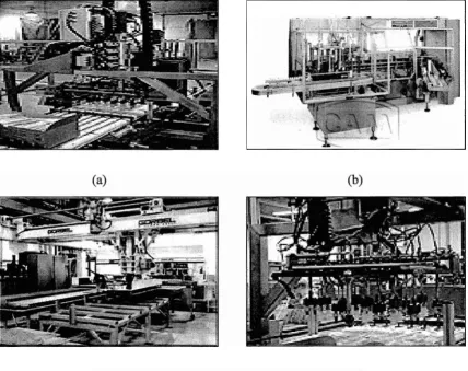
(a-d) Example of pick and place system
Servo controlled pick and place system
Station 1
Loading Process
Station 2
Pick and place system
Inductive Proximity Sensor
Capacitive Proximity Sensor
Standard Diffuse Sensor
Reed Switch
Type of cables
Position control Terminal Blocks
Servo control terminal block connection
PLC CJlH-G (CJlW-NC413)
SCADA host
Pick and place system
Project process flow
Project concept
Ladder Diagram Section 1
Ladder Diagram Section 2
Ladder Diagram Section 3
Ladder Diagram Section 4
Ladder Diagram Section 5
Ladder Diagram Section 5 (continued)
Ladder Diagram END
Ladder Diagram Section 1
Ladder Diagram Section 1 (continued)
Ladder Diagram Section 2
Ladder Diagram Section 3
Ladder Diagram Section 4
Ladder Diagram Section 5
Ladder Diagram Section 5 (continued)
Front page
Main menu page
System layout page
Alarm page
Virtual Alarm
Servo motor parameter
4.22 Main menu page
4.23 System layout page
4.24 Alarm page
4.25 Example of alarm alert
4.26 Example of Virtual alarm
APPENDIX
LIST OF APPENDICES
TITLE
Gantt chart
Data sheet servo motor CX-Designer Catalogue
GLOSARY
SCADA
-
Supervisory Control and Data Acquisition PLC-
Programmable Logic ControllerRTU Remote Terminal Unit
RS - Remote Station
CHAPTER 1 INTRODUCTION
- .
1.1 Definition
SCADA is an acronym that stands for Supervisory Control and Data Acquisition.
A SCADA system is a common process automation system which is used to gather data
fYom sensors and instruments located at remote sites and to transmit and display this data
at a central site for either control or monitoring purposes. SCADA is widely use in
power plants, oil and gas refining, transportation, telecorntnunication, various treatment
plants and in control of waste and water.
SCADA system basically measurement and control system. It not a real time
control but is placed in addition to real time control for controlling process external to
SCADA. A SCADA system can be relatively simple, such as one that monitors
environmental conditions of a small office building or incredibly complex, such as a
system that monitors all the activity in a nuclear power plant. A SCADA system
example application is in pipeline system where its gather information of a leak on a
pipeline has occurred, carrying out necessary analysis and control, such as determining
if the leak is critical and displaying the information in a logical and organized way.
SCADA systems are the heart of the modern industrial enterprise raging fkom
mining plants, water and electrical utility installation to oil and gas plant. SCADA
large process but not many students familiar with this automation system process. It is crucial for students to familiar with this SCADA system in order to expose then with a real life automation industries.
1.2
General Description ( Project Overview)This project comprises of integration of Supervisory Data and Data Acquisition (SCADA), programmable logic controllers (PLC), pneumatics and electrical actuators. In this project, SCADA will be the central system that control and monitors all the data from sensors and transducers in the system. There are two main sites in this project which are master site and remote site. Master site consist of SCADA host which is a single computer that running CX-Designer software, a sophisticated Human Machine
Interface (HMI) that responsible to communicate with field instrument. While remote site, - consist of programmable logic controller (PLC) and field instrument. The
completion of this project will produce a complete industrial prototype automation system that will be used for teaching and learning purposes in automation subject.
1.3 Problem Statements
The goal of this project is to develop a training kit machine for UTeM students specialize in Automation. This training kit will use an up to date approach of teaching and learning concept especially for practice and application. Even though students were exposed more to PLC as a main control of automation system but the development of SCADA in this training kit is crucial to expose them with the real life of process control in automation industries. In automation industries, PLC will run a pre programmed
reality makes the teaching and learning process not so effective. The integration of
Supervisory Data and Data Acquisition (SCADA), programmable logic controllers
(PLC), pneumatics and electrical actuators will produce a complete industrial training kit
machine that will attract student to be more enthusiasm in the process of learning.
1.4 Project Objectives
The main objectives of this project are:
To develop SCADA for the servo controlled pick and place system.
To use SCADA as the central system that control and monitors all the data
from sensors and transducers in the system servo controlled pick and place
system.
To produce complete industrial prototype automation that will be used for
teaching and learning purposes.
1.5 Project Scope
The project scopes for implementation of this project are:
This project comprises of integration between SCADA, PLC, pneumatics and
electrical actuators for a complete servo controlled pick and place system.
CHAPTER 2 LITERATURE REVIEW
This chapter will discuss about the sources or articles that were related to the project. All the information and details of the project were from the source and research that have been done before.
2.1 SCADA System Overview
SCADA is acronym for Supervisory Control and Data Acquisition. SCADA is a kind of software application program used in utility infrastructures as a computer-based monitoring and control system that centrally collects, displays, and stores information from remotely-located data collection transducers and sensors to support the control of equipment, devices, and automated functions. The system is composed of collecting information, transferring it back to a central control site or main station computer, conducting the necessary analysis and control, and then displaying the data on an operator screen. SCADA is handy for keeping a process in control as well as to diagnose
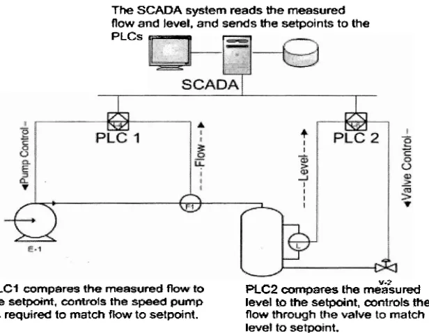
The SCADA system reads the measured
now and level. and sends the setDoints to the
PLCs
PLCI compares the measured flow to PLC2 cmqmes the m%%u&
the setpaint, controls rtra yssed pump level to the setpoint, controls the
as required lo match W w to setpoint. flow through the valve to match level to setps~nt.
~.
Figure 2.1: Example of real life SCADA system
- -
2.1.1 SCADA Systems Concepts
A SCADA system includes inputloutput signal hardware, controllers, HMI, networks, communication, database and software. SCADA system is the central system that control and monitor of such a site or system. A Remote Terminal Unit (RTU) or a
Programmable Logic Controller (PLC) automatically performed the remote site control. Host control functions are almost always restricted to basic site over-ride or supervisory level capability.
Data acquisition begins at the RTU or PLC level and includes meter readings and
[image:21.511.116.424.112.351.2]2.1.2 Human Machine Interface
A Human-Machine Interface (HMI) is the apparatus which presents process data to a human operator, and through which the human operator controls the process. The HMI industry was develop because the needed for a standardized way to monitor and to control multiple remote controllers, PLC and other control devices. An HMI may also be linked to a database, to provide trending, diagnostic data, and management information such as scheduled maintenance procedures, logistic information, detailed schematics for
a particular sensor or machine, and expert-system troubleshooting guides.
2.1.3 SCADA Main Components.
There are three main components in SCADA systems which are field
instrumentation and control equipment, communications network, remote terminal unit (RTU) and remote stations (RS) and central monitoring station (CMS).
. - . .
The Field Instrumentation or equipment refers to the sensors, meters and actuators, valves, relays or motors that are directly interfaced with the plant, equipment or pipeline. It is this equipment that will generate the analog andlor digital signals that will be monitored at the Remote Station. The signals are designed for compatibility with the RTU (Remote Terminal Unit) or PLC (Programmable Logic Control) located at the
remote stations
The Remote Station is located at the remote plant, equipment and monitoring station that is being monitored and controlled at the Central Monitoring Station's computer(s). The remote station can consist of either a RTU or PLC unit(s).
The Central Monitoring Station (CMS) is the central monitoring and control
station within the SCADA network system. The system can consist of one or several
controVmonitoring workstations. The Man Machine Interface (MMI) program provides
the link between the operator and the SCADA network system for both monitoring and
control of the system.
2.1.4 Benefits Of SCADA
Control units function as PLCs, RTUs, or DCUs;
Control units perform advanced measurement and control independent of the
central computer;
PID control continues, even if comrnunications to the main computer are
lost;
Control units have many channel types to measure most available sensors;
Systems are compatible with our own or other vendors' HMI software
packages; and
Control units have their own UPS; during ac power loss, they continue to
2.2 Pick And Place System
Pick and place system are the manipulators that designed to perform repetitive picking and placing in production floor at the automation industries. There are employed
[image:24.511.68.497.351.690.2]because of their precision and cost effectiveness. The pick and place systems are assembly and assist with sorting, picking, assembly, parts kitting, machine tending, packaging, boxing, palletizing and material handling. There are many different types of pick and place systems and each of it differ term of specifications, features, and applications. The example of pick and place system are portable material handling systems, pick and place robot manipulators, plant wide material handling systems, and pick and place machines.