This is a repository copy of
A disposable continuum endoscope using piston-driven
parallel bellow actuator
.
White Rose Research Online URL for this paper:
http://eprints.whiterose.ac.uk/126846/
Version: Accepted Version
Proceedings Paper:
Garbin, N, Wang, L, Chandler, JH orcid.org/0000-0001-9232-4966 et al. (3 more authors)
(2018) A disposable continuum endoscope using piston-driven parallel bellow actuator. In:
2018 International Symposium on Medical Robotics (ISMR). ISMR 2018, 01-03 Mar 2018,
Atlanta, USA. IEEE . ISBN 978-1-5386-2512-5
https://doi.org/10.1109/ISMR.2018.8333287
(c) 2018, IEEE. Personal use of this material is permitted. Permission from IEEE must be
obtained for all other uses, in any current or future media, including reprinting/republishing
this material for advertising or promotional purposes, creating new collective works, for
resale or redistribution to servers or lists, or reuse of any copyrighted component of this
work in other works.
[email protected] https://eprints.whiterose.ac.uk/ Reuse
Items deposited in White Rose Research Online are protected by copyright, with all rights reserved unless indicated otherwise. They may be downloaded and/or printed for private study, or other acts as permitted by national copyright laws. The publisher or other rights holders may allow further reproduction and re-use of the full text version. This is indicated by the licence information on the White Rose Research Online record for the item.
Takedown
If you consider content in White Rose Research Online to be in breach of UK law, please notify us by
A Disposable Continuum Endoscope Using
Piston-driven Parallel Bellow Actuator
Nicolo Garbin
1, Long Wang
1, James H. Chandler
2, Keith L. Obstein
3,1, Nabil Simaan
1, Pietro Valdastri
2Abstract—This paper presents a novel low cost disposable continuum endoscope based on a piston-driven parallel bellow actuator design. The parallel bellow actuator achieves motion by being pressurized via displacement-controlled pistons. The displacements are generated by rack-and-pinion mechanisms using inexpensive stepper motors. The design concept provides a potential alternative solution to upper gastrointestinal (UGI) diagnosis. The modularity and the use of inexpensive components allow for low fabrication costs and disposability. The use of robotic assistance could facilitate the development of an easier interface for the gastroenterologists, avoiding the nonintuitive manipulation mapping of the traditional UGI endoscopes. We adapt existing kinematic solutions of multi-backbone contin-uum robots to model contincontin-uum parallel bellow actuators. An actuation compensation strategy is presented and validated to address the pneumatic compressibility through the transmission lines. The design concept was prototyped and tested with a custom control platform. The experimental validation shows that the actuation compensation was demonstrated to significantly improve orientation control of the endoscope end-effector. This paper shows the feasibility of the proposed design and lays the foundation toward clinical scenarios.
Index Terms—disposable endoscopy, soft robotic, rubber bel-lows, actuation compensation
I. INTRODUCTION
With the absence of rigid links and discrete joints, contin-uum robots are particularly suitable for applications involving interaction with delicate and amorphous structures [1]. A potential use case for continuum robotics is in upper gas-trointestinal (UGI) tract screening. Currently, Esophagogas-troduodenoscopy (EGD) is the preferred diagnostic-screening method [2], [3] which involves the insertion of an endoscopic device with onboard camera through the esophagus to allow
Research reported in this article was supported by the Royal Society under grant number CH160052, by the Engineering and Physical Sciences Research Council (EPSRC) under grant number EP/P027938/1, in part by the National Institute of Biomedical Imaging and Bioengineering of the National Institute of Health under Award Number R01EB018992, and in part by the Vanderbilt Institute for Surgery and Engineering (ViSE). Any opinions, findings and conclusions, or recommendations expressed in this article are those of the authors and do not necessarily reflect the views of the Royal Society, EPSRC, NIH or ViSE.
1 Nicolo Garbin, Long Wang, Keith L. Obstein and Nabil Simaan
are with the Department of Mechanical Engineering, Vanderbilt Uni-versity, Nashville, TN 37212, USA. e-mail: (nicolo.garbin.1, long.wang, nabil.simaan)@vanderbilt.edu
2 James H. Chandler and Pietro Valdastri are with the Department of
Electronic and Electrical Engineering, University of Leeds, Leeds, UK. e-mail: (J.H.Chandler, P.Valdastri)@leeds.ac.uk
3Keith L. Obstein is with the Department of Gastroenterology, Hepatology,
Nutrition, Vanderbilt University Medical Center, Nashville, TN 37212, USA. e-mail: [email protected]
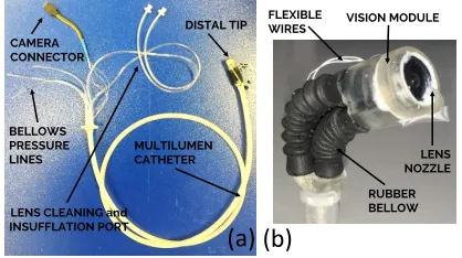
RUBBER BELLOW VISION MODULE FLEXIBLE
WIRES
LENS NOZZLE MULTILUMEN
CATHETER DISTAL TIP CAMERA
CONNECTOR
LENS CLEANING and INSUFFLATION PORT BELLOWS PRESSURE LINES
[image:2.612.336.545.169.286.2](a) (b)
Fig. 1: Disposable flexible endoscope: (a) Overview of the endoscope; (b) Detail of the distal endoscopic viewing tip.
visual inspection of the UGI tract. EDG requires expensive and bulky equipment, trained personnel [4] and can only be performed in specialized units (e.g. Endoscopic unit, Emer-gency department, Intensive Care Unit). Endoscopic control is also nonintuitive, using a double-dial and wire mechanism to convert thumb motion into tip actuation [5] and requires costly reprocessing (average cost:$160per scope per procedure [6]). This makes endoscopes failure prone and can result in added downtime and cost for specialist repair.
The disposable endoscope concept has been realised for colonoscopy in the form of the InvendoSCope SC210(Invendo Medical, Kissing, Germany). However, the current dimensions of this device would not allow its direct translation to EGD. The HydroJet concept has also been proposed as a disposable endoscopic device using four water jets to provide actuation force at the instrument tip, with direct application in EGD [7]. The device is primarily limited by its range of motion and lack of controlled retroflexion (i.e. ability of a traditional endoscope to look back), which makes inspection of the entire stomach challenging.
The proposed device in this work was inspired by the Bionic Handling Assistant by Festo [8] and catheter based continuum robots [9], and it takes the form of pneumatically actuated endoscope with a parallel bellow actuators (PBA) [9– 12] forming a steerable tip. We propose that pressure lines and therefore bellow extensions in this work are controlled using independent electromechanically driven syringes.
both pneumatic actuated manipulators and tendon (backbone) driven robots. This need motivates the adoption of kinematic model of multi-backbone continuum robots for pneumatic parallel bellow actuators use.
The contributions of this paper lie in two areas. First, a low-cost, disposable endoscopic device for potential application in EGD is presented in which electromechanically driven syringes are used to provide indirect pressurization. Second, we attempt to adapt the kinematic model of multi-backbone continuum robots for pneumatic parallel bellow actuators and an actuation compensation method is proposed to address the modeling inaccuracy and inconsistency.
II. MATERIAL AND METHOD
A. Disposable continuum endoscope
The disposable pneumatic endoscope consists of a flexible extruded catheter (Nusil MED-4880 silicone) with seven in-ternal channels (OD = 7mm, length = 120 cm). The cross-sectional profile of the catheter is shown in Fig. 2(c). An endoscopic viewing tip is coupled to the catheter at the distal end, while independent access to each lumen is facilitated with a bespoke 3D printed adapter at the proximal end. The six peripheral lumens of the flexible catheter are used for: power, camera and lighting wires (x1); insufflation (x1); irrigation (x1); and pressure lines for tip control (x3). The central lumen is reserved for a wire rope made out of 18-8 Stainless steel with a 7x19 arrangement, and it is used to stiffen the catheter. The endoscopic viewing tip is actuated via use of off-the-shelf rubber bellows (www.rubberstore.com, part number
BC−2305) to form a PBA [9–12]. A PBA consists of three
bellows arranged in parallel at the vertices of an equilateral triangle (Fig. 2(a)). A common moving end platform is hence controlled in 3 Degrees of Freedom (DoF) by controlling the bellows internal pressure. By changing the bellows design, it is possible to change the manipulator range of motion as well as its overall outer diameter. Three bellows (part number
BC−2305) (B = 5.6mm connector, 7.5mm max, 14mm
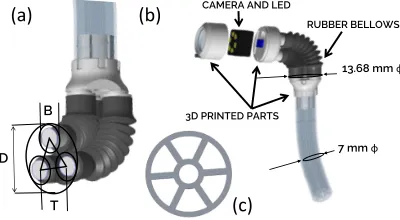
to 29mm variable length) at the vertexes of an equilateral triangle with sideT = 7 mm, define a tip with diameterD of 13.68mm, see Fig. 2(a).
7 mm 13.68 mm RUBBER BELLOWS CAMERA AND LED
3D PRINTED PARTS B
T D
(a) (b)
[image:3.612.73.273.547.657.2](c)
Fig. 2: CAD model of the distal steerable tip: (a) the bellows arranged in parallel having a diameter of 13.68 mm; (b) the distal tip that is connected to the multi-channel catheter and that is embedded with a camera having illumination; (c) cross sectional view of the multi-lumen catheter.
A CMOS camera (1.3 Megapixel, 5-8cm focal length, dimensions: 9mm×9mm×9mm) is embedded at the tip
(RA78080A-60 Bangu Technology Development CO., Baoan, China). Three ultra-low power Light Emitting Diodes (LEDs) (EAHC2835WD4, Everlight Electronics, Taipei, Taiwan) sur-round the camera to provide bright illumination. The endo-scope tip casing and connectors were 3D printed in resin (RS-F2-GPCL-02, Clear, FormLabs Somerville, MA, USA). Epoxy glue (Marine Epoxy, Loctite) was applied to the component joins to ensure a waterproof seal. The irrigation conduit is extended from the multi-lumen catheter channel to the tip of the endoscope via a highly flexible single lumen catheter (6 Fr, 0.003” wall thickness Pebax-35D, Apollo Medical Extrusion, UT, USA). Power and camera communication signals connect from the multi-lumen catheter to the tip using flexible wires (Calmont, California, USA). This configuration allows these components to bypass the PBA bending section without com-promising its mobility.
The proximal extremity of the multi-lumen catheter pro-vides direct coupling to each channel. Camera wires can be connected to a frame grabber for visualization, and insufflation and lens cleaning channels have a luer lock connector for use with standard syringes or pumping systems. Finally, actuation of the distal tip can be performed through connection of external pressure lines to each independent bellows lumens.
As the device is comprised of a small number of extruded, off-the-shelf and 3D printed parts, which are integrated within simple design, it is financially feasible for the scope to be disposable. The current version was assembled with an embedded 15 USD camera which can also be disposed of. If better quality camera is required, the design may be adapted to facilitate camera retrieval for reuse.
B. Actuation system
The PBA range of motion depends on the pressure inside the bellows. Given the soft nature of the bellows (Nitrile, E=3MPa), the pressure rating used to actuated the PBA is relatively low (<6 PSI) when compared to other pneumatic systems (HydroJet [7] actuating pressure: 100 PSI of pressur-ized water, STIFF FLOP [15] max actuating pressure: 20 PSI). Lower pressure removes the need for pneumatic control valves and a high-pressure source such a pressurized tank.
A suitable pressure range was achieved using standard 3 ml syringes (Qosina Corporation, NY USA). By controlling the syringe’s piston position, the pressure inside the bellows is varied; positive and negative pressures inducing elongation and contraction respectively.
improved resolution (16 micro-steps per step) were used to digitally control stepper position and therefore the piston of the syringe. Each bellow pressure line is hence controlled by actuating the stepper motor. For the specified components, the resolution of the piston position is 0.0294 mm per micro step.
III. KINEMATICMODELING
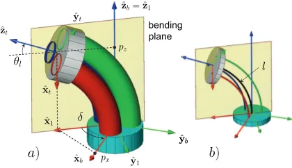
Previous works [8], [9] formulated the kinematic model using internal pressure and the length of each bellow as joint space variables, both of which rely on direct pressure control. Inspired by these works, this paper proposes a closed-form kinematic model for parallel bellow actuators. This model is adapted from existing multi-backbone continuum robots where the center lines of parallel bellows are used to describe the kinematic state (Fig. 3). Constant curvature assumption is applied on all bellow center lines in this work.
ˆ
zt
θl
ˆ
yt
ˆ
zb= ˆz1
pz
ˆ
xt
ˆ
x1 δ
px
ˆ
xb
bending plane
l
a) b)
ˆ
y1 ˆ
yb
ˆ
[image:4.612.69.279.277.398.2]yb
Fig. 3: Kinematic nomenclature of the parallel bellow actuator: (a) schematic representation of a PBA continuum segment; (b) illustra-tion of the center lines of each bellow.
As illustrated in Fig. 3, the kinematic problem of parallel bellow actuators aims to capture the relationship between the endoscope viewing tip pose (position and orientation) and the joint space variables (the electromechanically driven syringe positions). The endoscope viewing tip pose is denoted as [x,R], termedtask space, while the bellows change of length is denoted as qcalled the joint space.
x= [px, py, pz]T, R=bRt, R∈SO(3) (1)
q= [q1, q2, q3]T (2)
To bridge the task space and the joint space of continuum robots, another kinematic space -configuration space- is usu-ally defined (as described in [17]). In the case of the proposed continuum endoscope, the configuration space variable, ψ, refers to the geometric variables that characterize the shape of the continuum segment - the bending angle at the tip θl,
the angle of the plane in which the segment bends δ, and the imaginary central backbone length of the robotl.
ψ,[θl, δ, l]T (3)
There are then two kinematic mappings to be derived-the mapping from task space to configuration space, and derived-the mapping from configuration space to joint space:
FT : ψ[x,R] config. to task space (4)
Fq: ψq config. to joint space (5)
The tip position vector x and the rotation matrix R rep-resenting the tip orientation can be expressed as in (6-8), resulting in the configuration to task space mappingFT as:
x=e−δ[z∧]
Z l
0
[cθ(s),0, sθ(s)]Tds, l∈[Lmin, Lmax] (6)
R=e−δ[z∧]e(θ0−θl)[y∧]eδ[z∧] (7)
θ(s) =θ0+
Z s
0
κ(τ)dτ, s∈[0, l] (8)
where c(·) and s(·) denote the cosine and sine functions, and[a∧] represents a skew symmetric matrix generated from vector a, the variable s denotes the curve length along the imaginary primary backbone, and θ0 is the initial bending angle (θ0 = π2). The parameters Lmin and Lmax denote the
maximum and minimum lengths of the imaginary central backbone of the continuum endoscope. Using the constant curvature assumption, the curvature function κ(s) and the bending angleθ(s)become:
κ(s) = (θl−θ0)/l, θ(s) =θ0+s
l(θl−θ0) =θ(s, l) (9)
The configuration to joint space mapping Fq solves the joint displacements q, given the bending shape and length configurationψ. This problem was solved in details in [18]: (i) by projecting the secondary backbone onto the bending plane, the problem of solving the secondary backbone length becomes solving the projected length; (ii) the projected length is obtained by calculating the radius difference - the projection of the constant apart distance,∆i.
qi=li−l0, li= l+ ∆i(θl−θ0) (10)
∆i=rcosσi, σi=δ+23π(i−1), i∈[1,3] (11) where the parameterl0represents the bellow length at rest (i.e. internal pressure = atmospheric one), the variablel represents the current length of the imaginary central backbone, and the calculated expression li represents the length of the ith
bellow center line. The termris the distance in the base plane between bellow center line and imaginary primary backbone.
IV. ACTUATIONCOMPENSATION
Among research works on multi-backbone continuum robots, methods for modeling and compensating the extensions in the transmission lines were explored in [19], [20]. Inspired by these works, and as a preliminary investigation of the characteristic of the proposed transmission design, we discuss the actuation compensation problem in this section.
A. Motion transmission modeling - extension and backlash
ˆ
zb
θl
ˆ
zt
ˆ
xb
qi
qi ε
ε kbi
kti
τi q˜i τi
λ
[image:5.612.71.284.157.222.2]λ
Fig. 4: The schematic of motion transmission modeling with the extension εand the backlash λ.
The variableqi denotes the idealized displacement provided
at the base of the ith bellow, which is consistent with the
modeled displacement in (10). The variable qei is then used
to represent the displacement provided at the actuator, which will suffer from the transmission losses. In this work we formulate the modeling and compensation of transmission losses to include two terms: an actuation extension ε and an backlash uncertainties λ.
e
q,[eq1,eq2,eq3]T, qe=q+ε+λ, ε,λ∈IR3 (12) To model the extension ε, we assume: 1) only constant longitudinal stiffness and effective cross-section area exist along each individual bellow length and its effective cross-sectional area is constant, i.e. linear relationship between bellow length variation qi and its pressure pi, and 2) friction
is negligible through the transmission line.
Using the first assumption, with a nominal longitudinal stiffness value kbi for each bellow, the actuation forces τ at
the base of each bellow can be expressed as:
τ ,[τ1, τ2, τ3]T, τi=piA=kbi(li−l0) (13) Considering the fluid compression as a spring having a stiffness ofktiand using the second assumption of frictionless
transmission, we haveτi=ktiεi. Equating it and (13), we then
have:
ε= [ε1, ε2, ε3]T, εi=kεiqi, kεi ,(kbi/kti) (14)
where a dimensionless gain kεi is introduced for simplicity,
and defined as the ratio between the bellow and transmission stiffness.
The backlash uncertainty λis modeled as directional con-stant biases, similar to [20]:
λ= [λ1, λ2, λ3]T, λi=kλisgn( ˙qi) (15) where, in practise, the gain kλi may vary in positive and
negative directions and thesng(·)function may be replaced a
tangent hyperbolic function.
Combining (14) and (15), we write the expression of com-pensated joint displacements as:
e
q=q+Kεq+Kλsgn( ˙q) Kε,Kλ∈IR3×3 (16)
Kε= diag (kε), Kλ= diag (kλ), kε,kλ∈IR3 (17)
B. Actuation compensation parameter estimation
We rewrite (16) toward the parameter estimation as:
e
q=q+ diag(q)kε+ diag(sgn( ˙q))kλ (18)
Combining the two unknown parameter vectors as one, the estimation becomes a linear least-squared problem as:
kx,
(kε)T,(kλ)T T
, kx∈IR6×1 (19)
A kx = b, A∈IR3×6, b∈IR3×1 (20)
A(q,q˙) = diag(q) diag (sign( ˙q)) , b=qe−q (21) where A and b are the measurement matrix and vector, respectively. For the case ofN measurements, we have:
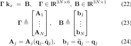
Γ kx = B, Γ∈IR3N×6, B∈IR3N×1 (22)
Γ,
A1 .. .
AN
, B,
b1 .. . bN
(23)
Aj =Aj(qj,q˙j), bj=qej−qj (24)
whereΓ andB are the aggregated measurement matrix and vector, and the subscriptj indicates thejth measurement.
A weighted linear least-squared solution can be obtained as the following:
ksol = (ΓTWΓ)−1ΓTW B (25)
W= diag(w1)T, . . . ,(wN)T T
, W∈IR3N×3N (26)
where the weight matrixWis given by the weight vectorwj
of each measurement. Finally, we propose to use the linear least-squared estimation in an iterative method.
Algorithm 1Iterative Linear Least-squared Estimation
Input: D{(eqj,ψej), j= 1, . . . , N};kx0,β >0
1: STARTInitialize:ki←kx0,k0←0
2: whilekkki−ki−1k
ki−1k ≥βdo
3: Applykito control, and collect new dataD{(eqj,ψej).
4: Updateki+1usingD{(eqj,eψj):
ki+1= (Γ T
WΓ)−1ΓTW B
5: end while
Output:k∗←k
i
V. EXPERIMENTAL VALIDATION
A. Experimental Setup
[image:5.612.352.562.279.353.2]EM TRACKER TRAKSTAR
Continuum Endoscope Phantom MATLAB SIMULINK
REAL-TIME PC
NI DAQ SCB-68
HOST PC
SYRINGE 1 DRIVER 1 DRIVER 2 DRIVER 3
SYRINGE 2 SYRINGE 3
STEPPER 1 STEPPER 2 STEPPER 3
PINION RACK 1 PINION RACK 2 PINION RACK 3
Motor Control
(a)
(b)
(c)
ˆ yb xˆb
ˆ zb
ˆ xt
ˆ yt
[image:6.612.88.531.49.178.2]ˆ zt
Fig. 5: Experimental setup: (a) schematic of the acquisition and control system via real-time Matlab SimulinkTM; (b) closed-up view of the continuum endoscope phantom used for validation. EM sensors are used to trackˆxb,yˆb,ˆzt; (c) view of the actuation control system.
to control the stepper motors via Data Acquisition (DAQ) board (National Instrument SCB-68) at 2kHz frequency. The target machine also interfaces with an Electromagnetic (EM) Trackeing system (3D Guidance trakSTAR - Ascension, NDI, Waterloo, Canada) at 125Hz. Three 6-Dof EM sensors (shown in Fig. 5(b)) were used to track the end effector positions, and orientation with respect to the manipulator base frame.
A phantom end-effector was used having comparable weight to the actual camera viewing tip of the disposable device (2.58 gr). A detailed view of an inexpensive actuation system is shown in fig. 5(c). Given the small form factor of the actuation system, if controlled via micro controller (µC) and battery operated, it can fit a backpack facilitating system portability.
B. Parameter estimation for actuation compensation
As described in section IV, the actuation compensation method is parameterized by the extensionkεand the backlash
kλ. In this subsection, the estimation method to identify these parameters (as in section IV-B) is validated experimentally and the estimation result is reported. Equation (25) was used in an iterative fashion, where an estimate of k is updated given a new experimental data set. Such input data sets were collected for each iteration, and each set consisted of 120 robot state measurements that were recorded while the robot continuum segment was commanded to bend in 12 different directions and 5 bending angles in each direction. A relative convergence criterion was used for the estimation of the compensation gain, where a threshold of 2% was applied.
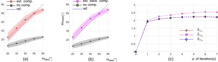
The optimal estimated k∗ = [kTε,kTλ]T was found to be [2.22,2.53,2.21,0.87,0.92,0.81]T. Figure 6 shows the results and reflects the difference between the control of the endo-scopic viewing tip with and without compensation. Both of Fig. 6 (a) and (b) show significant improvements on bending angle accuracy compared to the scenario with no compensa-tion, reducing the root mean squared errors (RMSEs) from 36.96◦ to7.76◦ (shown in (b)). Further comparing closely (a) and (b), adding the backlash compensation helped to create a slightly smaller boundary of uncertainty and the overall RMSE was also slightly improved, from8.04◦from the case with only extension compensation, to7.76◦after backlash compensation
added. Figure 6(c) shows conversion of the kε that occurred
within 7 iterations.
VI. DISCUSSION AND FUTURE WORK
The proposed actuation compensation reduced the error between desired and actual bending angle from a root mean squared error (RMSE) of 37.0◦, when no compensation is provided, to a RMSE of7.8◦. While the accuracy improvement was significant, the absolute accuracy, RMSE of 7.8◦, may not be sufficient for automatic or semi-automatic endoscopic procedures. However, we believe that the framework put forth in this work has a big potential which is worth investigating. Through increasing the sophistication of the current model, we expect to improve accuracy when compensating for extension and backlash errors. For example, constant curvature shape assumption can be improved through the use of a modal representation [21]. In addition, the extension compensation gains are constant and independent of the robot configuration (bending direction and bending angle). With the addition of a configuration dependent term, e.g. kx = kx(ψ) or kx = kx(q), compensation accuracy may be more accurate across the entire work space.
To facilitate closed loop control of the device, an inexpen-sive 9 DoFs inertial measurement unit (accelerometer, gyro-scope, magnetometer) may be incorporated into the moving tip, delivering orientation information relative to an inertial reference frame. The EM trackers used in the experimental validation are too expensive for integration into a clinical version of the device.
VII. CONCLUSION
(a) Θdes[◦] (b) (c)
Θdes[◦] # of iteration(s)
Θ
me
as
[
◦
]
Θ
me
as
[
◦
]
kε1 kε2 kε3 ref.
no comp. ext. comp.
[image:7.612.100.517.53.172.2]ref. no comp. ext. back. comp.
Fig. 6: Results of actuation compensation: (a) the comparison between extension compensation and no compensation; (b) the comparison between extension and backlash compensation, and no compensation; (c) convergence of the iterative compensation gain parameters estimation. In (a) and (b), the notation of angle Θx is used to denote the complementary angle to θx. The lines represent the mean values and the
shading areas highlight the boundaries determined by (±standard deviation).
compensation method improved the orientation accuracy from 36.96◦ to7.76◦.
Screening of the UGI tract is still an expensive and invasive procedure. Traditional endoscopes require trained personnel and can only be performed in dedicated unit. A robotic diagnostic disposable endoscope provide a cheaper, and easier to use solution that can help with routine operation as well as mass screening programs [22].
We have paved the way to the development of a much sim-pler to use and cheaper robotic endoscopic device. Compensa-tion drastically decreases end effector posiCompensa-tion and orientaCompensa-tion errors. The proposed adoption of existing modeling methods in multi-backbone continuum robots showed an interesting direction that may benefit other similar parallel bellow actuator designs.
REFERENCES
[1] G. Chen, M. T. Pham, and T. Redarce, “Sensor-based guidance control of a continuum robot for a semi-autonomous colonoscopy,”Robotics and autonomous systems, vol. 57, no. 6, pp. 712–722, 2009.
[2] K. S. Choi, M.-S. Kwak, H.-y. Lee, J. K. Jun, M.-I. Hahm, and E.-C. Park, “Screening for gastric cancer in korea: population-based preferences for endoscopy versus upper gastrointestinal series,”Cancer Epidemiology and Prevention Biomarkers, vol. 18, no. 5, pp. 1390–1398, 2009.
[3] A. Tashiro, M. Sano, K. Kinameri, K. Fujita, and Y. Takeuchi, “Com-paring mass screening techniques for gastric cancer in japan,”World journal of gastroenterology: WJG, vol. 12, no. 30, p. 4873, 2006. [4] O. W. Cass, M. L. Freeman, C. J. Peine, R. T. Zera, and G. R. Onstad,
“Objective evaluation of endoscopy skills during training,”Annals of internal medicine, vol. 118, no. 1, pp. 40–44, 1993.
[5] G. Harvin, “Review of musculoskeletal injuries and prevention in the endoscopy practitioner,” Journal of clinical gastroenterology, vol. 48, no. 7, p. 590, 2014.
[6] C. L. Ofstead, M. R. Quick, J. E. Eiland, and S. J. Adams, “A glimpse at the true cost of reprocessing endoscopes.”
[7] R. Caprara, K. L. Obstein, G. Scozzarro, C. Di Natali, M. Beccani, D. R. Morgan, and P. Valdastri, “A platform for gastric cancer screening in low-and middle-income countries,” IEEE Transactions on Biomedical Engineering, vol. 62, no. 5, pp. 1324–1332, 2015.
[8] T. Mahl, A. Hildebrandt, and O. Sawodny, “A variable curvature contin-uum kinematics for kinematic control of the bionic handling assistant,” IEEE transactions on robotics, vol. 30, no. 4, pp. 935–949, 2014. [9] Y. Bailly and Y. Amirat, “Modeling and control of a hybrid continuum
active catheter for aortic aneurysm treatment,” inRobotics and Automa-tion, 2005. ICRA 2005. Proceedings of the 2005 IEEE International Conference on. IEEE, 2005, pp. 924–929.
[10] T. Gagarina and P. Joli, “Modeling and experimental analysis of a new bellow type actuators for active catheter end-effector,” in Robot and Human Interactive Communication, 2001. Proceedings. 10th IEEE International Workshop on. IEEE, 2001, pp. 612–617.
[11] M. Sfakiotakis, D. Laue, and B. C. Davies, “An experimental undulating-fin device using the parallel bellows actuator,” inRobotics and Automa-tion, 2001. Proceedings 2001 ICRA. IEEE International Conference on, vol. 3. IEEE, 2001, pp. 2356–2362.
[12] D. O’Brien and D. M. Lane, “3d force control system design for a hydraulic parallel bellows continuum actuator,” inRobotics and Automa-tion, 2001. Proceedings 2001 ICRA. IEEE International Conference on, vol. 3. IEEE, 2001, pp. 2375–2380.
[13] M. Cianchetti, T. Ranzani, G. Gerboni, I. De Falco, C. Laschi, and A. Menciassi, “Stiff-flop surgical manipulator: mechanical design and experimental characterization of the single module,” in2013 IEEE/RSJ International Conference on Intelligent Robots and Systems. IEEE, 2013, pp. 3576–3581.
[14] A. Stilli, H. A. Wurdemann, and K. Althoefer, “Shrinkable, stiffness-controllable soft manipulator based on a bio-inspired antagonistic actu-ation principle,” inIntelligent Robots and Systems (IROS 2014), 2014 IEEE/RSJ International Conference on. IEEE, 2014, pp. 2476–2481. [15] A. Shiva, A. Stilli, Y. Noh, A. Faragasso, I. De Falco, G. Gerboni,
M. Cianchetti, A. Menciassi, K. Althoefer, and H. A. Wurdemann, “Tendon-based stiffening for a pneumatically actuated soft manipulator,” IEEE Robotics and Automation Letters, vol. 1, no. 2, pp. 632–637, 2016. [16] J. Fra´s, J. Czarnowski, M. Macia´s, J. Gł´owka, M. Cianchetti, and A. Menciassi, “New stiff-flop module construction idea for improved actuation and sensing,” inRobotics and Automation (ICRA), 2015 IEEE International Conference on. IEEE, 2015, pp. 2901–2906.
[17] N. Simaan, K. Xu, W. Wei, A. Kapoor, P. Kazanzides, R. Taylor, and P. Flint, “Design and integration of a telerobotic system for minimally invasive surgery of the throat,” The International journal of robotics research, vol. 28, no. 9, pp. 1134–1153, 2009.
[18] N. Simaan, “Snake-like units using flexible backbones and actuation redundancy for enhanced miniaturization,” inRobotics and Automation, 2005. ICRA 2005. Proceedings of the 2005 IEEE International Confer-ence on. IEEE, 2005, pp. 3012–3017.
[19] K. Xu and N. Simaan, “Actuation compensation for flexible surgical snake-like robots with redundant remote actuation,” in Robotics and Automation, 2006. ICRA 2006. Proceedings 2006 IEEE International Conference on. IEEE, 2006, pp. 4148–4154.
[20] R. Roy, L. Wang, and N. Simaan, “Modeling and estimation of friction, extension, and coupling effects in multisegment continuum robots,” IEEE/ASME Transactions on Mechatronics, vol. 22, no. 2, pp. 909–920, 2017.
[21] L. Wang and N. Simaan, “Investigation of error propagation in multi-backbone continuum robots,” in Advances in Robot Kinematics. Springer, 2014, pp. 385–394.