DEVELOPMENT OF A ‘SMART’ MONOLAYER APPLICATION SYSTEM FOR REDUCING EVAPORATION FROM FARM DAMS – INTRODUCTORY PAPER
G.N. Brink1, T.W. Symes2 and N.H. Hancock1
1
Faculty of Engineering & Surveying, National Centre for Engineering in Agriculture, and CRC for Irrigation Futures, University of Southern Queensland, Toowoomba. QLD 4350
2
National Centre for Engineering in Agriculture, and CRC for Irrigation Futures, University of Southern Queensland, Toowoomba. QLD 4350
ABSTRACT
Chemical monolayer films are potentially an economical low-impact means of reducing
evaporative loss from farm water storages. However, their performance can be highly variable as they are affected by climatic and environmental factors: principally wind, wave action and bio-degradation. These limitations must be accommodated for in the management of the applied monolayer by means of appropriate and timely autonomous application and re-application.
Although a number of autonomous application systems for monolayer already exist, none has proved overly successful. It is argued that whilst this is in part due to sub-optimal performance of monolayer materials, it is also due in large measure to inaccuracies and/or inappropriate design in both application systems and particularly application strategies which are not adaptive to the prevailing environmental conditions. Therefore, a control system is being developed to adaptively and spatially vary monolayer application rates according to changing conditions monitored on-site. This will form part of an autonomous electromechanical system for the optimal application and spreading of chemical monolayer.
This paper reports progress towards this objective; firstly by evaluation of the design requirements for automated systems at a range of spatial scales; and secondly via the construction of a first „pre-prototype‟ to act as an evaluation platform and concept demonstrator.
Keywords: chemical monolayer, autonomous, electromechanical, low-impact, water, evaporation reduction, pre-prototype, application, farm dam.
INTRODUCTION
Today annual evaporation losses from farm water storages in Australia can potentially exceed 40% of their storage volume (Craig et al. 2005a). Baillie (2008) estimates evaporation losses from on farm storages in Australia to be in the range of 1,320GL to 2,880GL (depending on storage volume, evaporation potential and storage characteristics). In addition, considerable water distribution losses are present in irrigation channels due to evaporation and seepage (Baillie et al. 2007). As a consequence, agricultural production opportunities worth tens of millions of dollars evaporate with the water.
Evaporation losses can be minimised to some extent through the design of deep, small surface-area-storages or construction of partition walls within storages („cells‟) (Baillie et al. 2007). Also the use of wind barriers, shelter belts and dam destratification (for deeper storages) can help to reduce evaporative loss (Brown 1988). Commercial products such as physical covers (e.g. „E-Vap-Cap1‟), suspended shade structures (e.g. „NetPro2‟), modular floating objects and chemical
monolayers (e.g.‟WaterSavr3‟) are also available, some of which have been evaluated by the
1 http://www.evaporationcontrol.com.au/ 2
http://www.netprocanopies.com/
National Centre for Engineering in Agriculture (NCEA) with respect to performance and breakeven cost (Craig et al. 2005b). Table 1 summarises the product performance and breakeven costs of these products.
Table 1 Summary table of three commercially available evaporation mitigation products evaluated by the NCEA to determine their evaporative reduction performance (%), installed
cost ($/m²), operating and maintenance cost ($/ha/yr) and breakeven cost ($/ML saved) [reproduced from Craig et al. 2005b].
Product Evaporation Reduction (%) Installation Cost ($/m²) Operating & Maintenance Cost ($/ha/yr) Breakeven Cost ($/ML saved) Measured Small Tanks Potential Commercial Storage E-Vap-Cap
100%-94% High-Med-Low 95%-90%-85% Low-High $5.50-$8.50 Low-High $112-$572 Low-Med-High $302-$319-$338 NetPro 71%-69% 80%-70%-60% $7.00-$10.00 $112-$537 $296-$339-$395
WaterSavr 40%-10% 30%-15%-5% $0.00-$0.38 $826-$4,050 $130-$397-$1,191
Craig et al. (2005b) concluded that high evaporation savings are possible if physical covers are used on small farm dams less than 10ha in size. Physical covers can also be used on larger dams, but they are generally uneconomic due to the high capital investment required. In contrast, economic analyses indicate that for larger dams chemical monolayers present potentially the best option for conserving agricultural water in Australia; despite being less effective than physical structures (10-40% evaporative reduction compared with up to 90% for physical structures). However, the poor performance of currently available monolayer products highlights deficiencies in their physical and environmental durability, and also in the available application methods. The results of recent research at the NCEA indicate the potential for significant improvements in both the monolayer product, and in the application technology (Craig et al. 2007). Hence the objectives of the present work are:
to apply smart engineering technologies (sensing of the local environment, and spatially-varied adaptive control) to achieve timely and optimal application/re-application of monolayer to the water surface (minimum material use for maximum evaporative reduction); and
to provide autonomous, self-powered system/s for the application/re-application and spatial management of material appropriate to both present and future monolayer materials.
Recognising that many factors are likely to influence the design of monolayer application equipment, the initial approach adopted was that of producing a first pre-prototype system in the form of a „Demonstrator‟ for evaluation purposes. The development of this device is reported in this paper.
BACKGROUND
considered to make application easier, in comparison to powders, as liquids are easier to store, handle, distribute and apply (La Mer 1962).
The first attempts to apply monolayers under natural conditions to open water surfaces to reduce evaporation were some 53 years ago (Mansfield 1955). Since then a plethora of methods for applying a monolayer have followed, from Vines (1958) through to Lahav and Alto (1984). Many of the application methods developed during this era were often simple, mechanical and rather crude working prototypes. Also the management of monolayer application was only ever controlled in reference or direct proportion to wind speed and/or wind direction (Frenkiel 1965). As a result, very few application systems were ever commercialised.
In the published literature on evaporation mitigation employing monolayers, many references are made to the adverse effects of wind (Fitzgerald and Vines 1963; Frenkiel 1965; Crow 1961 and 1963; Reiser 1969). During field studies at Lake Hefner, U.S. Bureau of Reclamation researchers found wind to be the single most important factor in the application and maintenance of monolayer film (Fietz 1959). The deleterious effect of wind on a monolayer film is twofold; firstly wind displaces the film on the downwind shore, and secondly wind creates waves which can break-up the film. Through both these wind induced effects, monolayer film coverage across the water surface is effectively reduced. Crow (1963) and Reiser (1969) have both reported that a monolayer is unable to resist movement across the water surface under wind conditions and is moved at a speed of 1/31 of the wind speed. In addition, Reiser (1969) states that over long expanses, the re-application dosage rate for monolayer may have to be increased to accommodate for biological attrition, solution and/or volatilisation.
DESIGN REQUIREMENTS
Clearly some form of a mechanical apparatus is required to deploy the monolayer material. Recognising that for storages of significant area (hectares) monolayer application solely from the water‟s edge is likely to be inadequate (La Mer 1962), hence a floating mechanical structure was seen as a requirement. This decision implies the need for a reservoir of monolayer material and a solar/battery power supply for both control and implementation of the monolayer application.
In addition, sensors are required for accurately measuring and monitoring on-site environmental conditions that influence monolayer performance. The principal variables are:
(i) evaporative demand (i.e. the combination of solar radiation, humidity deficit and wind speed)
(ii) water temperature relative to air temperature; (iii) wind speed and direction; and
(iv) rainfall and rainfall rate.
The variation in environmental conditions indicated by these sensors directly influences dosing decisions. In this list (i) evaporative demand determines if monolayer application is economically justified; (ii) wind speed and direction influences the speed at which monolayer is been removed from the water surface and the direction it is being pushed, hence the required replenishment/re-application rate to be applied at the up-wind shore; (iii) relative temperature adjacent to the water surface affect the vertical stability of the water surface layers which impacts on monolayer
effectiveness (Gladyshev 2002); and (iv) rainfall (depending on magnitude and intensity) will cause break-up of the established monolayer film and also dispersal via mixing into the water body, which decreases coverage. (Further discussion of these phenomena is beyond the scope of this paper.)
The application demand to maintain an effective cover of monolayer on a farm water body will constantly be changing as influenced by on-site environmental conditions. Therefore, rate and frequency of monolayer application will need to be autonomously calculated in real-time by a „Coordinator Unit‟ (CU). This component will perform „system management‟ tasks, primarily the analysis of input data from sensors, applying algorithms to that data and decision support rules to calculate the instantaneous application/re-application rate for monolayer.
In a broader context it is recognised that these design requirements need to be specified with rigour and hence a formal Universal Design Framework had been conceived – Brink et al. (2009).
THE PRE-PROTOTYPE ‘DEMONSTRATOR’ SYSTEM
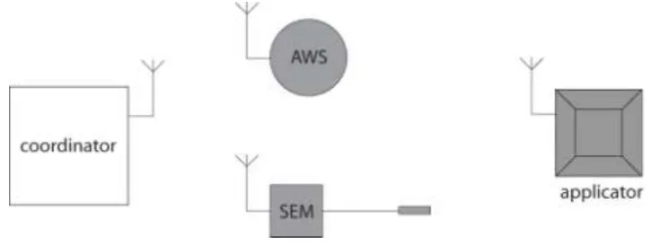
[image:4.595.119.482.296.432.2]The pre-prototype system has been set-up as detailed in Figure 1. The sensors, coordinator and applicator all communicate wirelessly. Data is sent from an Automatic Weather Station (AWS) and “Irrimate™ Seepage and Evaporation Meter” (SEM) to the CU for analysis. Once the coordinator has calculated the required application rate this information is sent to the applicator to action.
Figure 1 Schematic overview of the prototype ‘smart’ autonomous system for monolayer
application.
The AWS, SEM and Applicator each have a custom in-built controller unit based on an „ATMEL 644P‟ microprocessor, with „ZIGBEE PRO‟ radio modem for wireless communication. The CU, AWS, SEM and applicator operate in a meshed ad hoc network to wirelessly transfer data.
Sensors
The AWS is capable of measuring and recording air temperature, wind speed and direction, solar radiation, relative humidity and rainfall. The AWS automatically averages logged data daily, hourly, every fifteen minutes and every minute. The AWS has a wireless integrator for interrogating, downloading and sending the required AWS data to the CU. The controller is programmed to interrogate the AWS every minute for rainfall, and if rainfall is detected a warning is instantly sent to the CU. For all other climatic data, the AWS is interrogated only every fifteen minutes. This data is then sent to the CU for analysis.
An SEM is also employed for accurately measuring and recording changes in water depth due to seepage and/or evaporation. Changes in water depth are recorded every minute and averaged over fifteen minute intervals. This averaged data is then sent to the CU every hour for analysis.
Monolayer Applicator
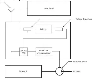
For maximum accuracy and reliability a 12V DC peristaltic pump is utilised which has the advantages of self-priming, being able to run dry and a low power requirement. The pump is powered by a sealed lead-acid (SLA) battery which is recharged by a polycrystalline solar panel (10W). Therefore, the applicator is fully self-powered and portable for remote applications where alternative power sources may be limited, unavailable and/or unviable. In addition, the voltage supplied to operate the pump is regulated at 10.0V because the pump flow rate is voltage dependant. A basic schematic diagram of the applicator design is provided in Figure 2.
The hardware selected for application of monolayer can be used to apply monolayer either from the shore or from a floating platform onto the water surface. To cover the entire surface of a typical large farm dam with monolayer a number of applicators would be required, most likely a
[image:5.595.138.510.243.561.2]combination of shore and floating applicators (Frenkiel 1965). To date a single floating applicator („pre-prototype‟) has been designed and constructed as allows maximum flexibility in evaluation at different location and on-site placement.
Figure 2 Schematic diagram of the Demonstrator System applicator design and hardware.
The application system hardware is housed in a custom built metal housing that has four closed-cell polyethylene foam floats attached for buoyancy, Figure 3(a). A 20L polypropylene reservoir for monolayer is also attached to the bottom of the metal housing surrounded by the foam floats, Figure 3(b). Although the capacity of the monolayer reservoir is only 20L for testing purposes, this would need to be increased for commercial applications, depending on the formulation of the monolayer product. The reservoir also has a refill line inside the metal housing which is accessed by removing the housing lid. The removable lid also allows easy access to application hardware for servicing, replacement, repair or modification, Figure 3(c).
[image:6.595.87.525.55.511.2]
Figure 3 Pre-prototype floating applicator; (a) three-quarter view of the applicator; (b) view underneath the applicator; (c) view inside the metal housing with the lid lifted; and (d)
schematic of the anchor and mooring set-up for the applicator on a farm dam.
Coordinator Unit (CU)
As introduced above, all dosing decisions are calculated and actioned by the CU based on the recommended application rates for the specific monolayer and in response to climatic conditions being monitored on-site. The CU performs the following tasks:
Transmit calculated application rate to each applicator.
Verify applications by logging each application timestamp and duration, which is also used for determining storage reservoir volume.
Communicate with the AWS and SEM to log data (environmental variables and depth measurement).
Use data to perform real-time decisions of application amount.
Transmit alarms and provide access to remote data via NextG modem.
Solar charge the battery (i.e. no back-up power source required).
As with the other system components the CU hardware consists of a custom circuit board with an Atmel 128L microprocessor, a „ZIGBEE PRO‟ radio modem, a NextG data modem for remote communications and a LCD display for inputs.
(a) (b)
(c) (d)
solar panel
reservoir metal housing
antenna
foam floats
pump
filler controller
anchor float anchor rope
Decision Support Rules
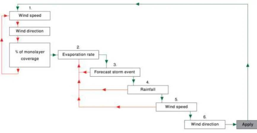
The dosing decisions are determined by a simple set of hierarchical rules in the form of an algorithm for real-time calculation of optimal dosage rate. The rules are structured as detailed in Figure 4. The decision to apply would be determined by the following steps:
Step 1: The wind speed and direction is continuously checked to determine the rate and direction of film drift and hence the amount of water surface covered by monolayer. When monolayer coverage drops below a set minimum, dosing decisions would be affected.
Step 2: Determine if evaporation rate is sufficiently high enough to justify application of monolayer. If evaporation rate is not high enough then stop.
Step 3: Determine if there is a storm event with high winds and/or rainfall expected and when it is predicted to reach the water storage. This information is assessed in relation to the evaporation rate to determine if it is economically justified to apply monolayer before the storm event hits. If monolayer application is justified, or there is no storm event predicted, the next decision is affected.
Step 4: If rainfall is detected wait (i.e. do not proceed to Step 5) until rain has stopped; then return to Step 2 and start over. However, if no rainfall is detected, then move to the next decision.
Step 5: Check if wind speed is below a nominated threshold value. Then determine the required application rate with regard to expected monolayer film drift to maintain an effective cover.
Step 6: Check wind direction to determine the expected direction of monolayer film drift. This information is used to inform which applicators to use to apply monolayer in-line with wind direction.
[image:7.595.85.519.457.682.2]Once the calculated amount of monolayer has been applied in-line with wind direction by the appropriate applicators, the dosing decisions process is started over again at Step 1.
Figure 4 Diagrammatic overview of decision support rules.
CONCLUSION
operation and comprises atmospheric sensing, a floating liquid-monolayer applicator, and a coordinator unit to implement application decisions. Following field trials, future work will refine the design of both the hardware components and monolayer application algorithm, and expand the system to multiple prototype applicator units, both shore-based and water-based.
Acknowledgements
This research was funded by the Cooperative Research Centre for Irrigation Futures, as part of the Storage Dam Evaporation Mitigation Project. The authors would like to thank staff from the National Centre for Engineering in Agriculture for their assistance and support.
References:
Baillie, C. (2008). Assessment of evaporation losses and evaporation mitigation technologies (EMTs) for on farm water storages across Australia, Technical report, National Centre for Engineering in Agriculture & CRC for Irrigation Futures, Toowoomba, QLD, 4350, Australia. [unpublished].
Baillie, J., Baillie, C., Heinrich, N. and Murray, A. (2007). On-farm water use efficiency in the Northern Murray-Darling Basin, Technical report by the National Centre for Engineering in Agriculture, Murray-Darling Basin Commission – Northern Darling Program, MDBC Publication No. 03/08, Canberra, ACT, 2601, Australia.
Barnes, G. (2008). The potential for monolayers to reduce the evaporation of water from large water storages Agricultural Water Management. 95:339-353.
Brink, G., Symes, T., Pittaway, P., Hancock, N., Pather, S. and Schmidt, E. (2009). „Smart‟ monolayer application and management to reduce evaporation from farm dams – formulation of a universal design framework, ERE Conference Proceedings, Noosa, QLD, Australia. [in press].
Brown, J. A. H. (1988). The potential for reducing open water evaporation losses: a review Hydrology and Water Resources Symposium, ANU, Canberra, p. 108-115.
Craig, I., Green, A., Scobie, M. & Schmidt, E. (2005b). Controlling evaporative loss from water storages, Technical report, National Centre for Engineering in Agriculture, Toowoomba, QLD, 4350, Australia. [unpublished].
Craig, I., Schmidt, E. & Hancock, N. (2005a). CRC-IF first stage RP2 research proposal:
evaporation mitigation tools, Technical report, National Centre for Engineering in Agriculture & CRC for Irrigation Futures, Toowoomba, QLD, 4350, Australia. [unpublished].
Craig, I., Aravinthan1, V., Bailie, C., Beswick, A., Barnes, G., Bradbury, R., Connell, L., Coop, P., Fellows, C., Fitzmaurice, L., Foley, J., Hancock, N., Lamb, D., Morrison, P., Misra, R., Mossad, R., Pittaway, P., Prime, E., Rees, S., Schmidt, E., Solomon, D., Symes, T. & Turnbull, D. (2007). Evaporation, seepage and water quality management in storage dams: a review of research methods Environmental Health, 7:81-94.
Crow, F. R. (1961). Reducing reservoir evaporation: application of surface films cuts losses Agricultural Engineering. 42:240-243.
Crow, F. R. (1963). The effect of wind on evaporation suppressing films and methods of
modification in the International Union of Geodesy and Geophysics. International association of scientific hydrology. General Assembly of Berkeley, California, p. 26-37.
Fietz, T. R. (1959). Water-loss investigations: Lake Hefner - 1958. Evaporation reduction investigations, report of the collaborators, Technical report, U.S. Bureau of Reclamation, Washington DC, United States.
Fitzgerald, L. and Vines, R. (1963). Retardation of evaporation by monolayer: Practical aspects of treatment of large storages Australian Journal of Applied Science. 14:340-346.
Frenkiel, J. (1965). Evaporation reduction: physical and chemical principles and review of experiments, UNESCO, Paris, France.
Gladyshev, M. (2002). Biophysics of the Surface Microlayer of Aquatic Ecosystems. IWA Publishing London, United Kingdom.
Lahav, N. & Alto, P. (1984). „Method and apparatus for treating the surface of a body of liquid‟, US Patent 4,455,266, June 1984.
La Mer, V. K. (1962). Retardation of evaporation by monolayers: transport processes. Academic Press, New York.
Mansfield, W. W. (1955). Influence of monolayers on the natural rate of evaporation of water Australian Journal of Applied Science. 175:247-249.
McMahon, C., Craig, I., Turnbull, D., Schmidt, E. & Hancock, N. (2008). Laboratory studies of wind stresses on surface film materials, 2007-2008, Technical report, National Centre for Engineering in Agriculture & CRC for Irrigation Futures, Toowoomba, QLD, 4350, Australia. [unpublished].
Morrison, P., Gill, R., Symes, T., Misra, R., Craig, I., Schmidt, E. and Hancock, N. (2008). Small scale evaporation mitigation trials, 2007-2008. National Centre for Engineering in Agriculture, Publication 1002040/1, Toowoomba, Queensland, Australia.
Reiser, C. O. (1969). A system for controlling water evaporation, Industrial and Engineering Chemical Research. 8:63-69.