International Journal of Innovative Technology and Exploring Engineering (IJITEE) ISSN: 2278-3075, Volume-8, Issue-11S2, September 2019
Abstract— a main objective of to the project is the Modular fusion solid state pulsed power generator with ripple content. Recently, a pulsed power structures have determined substantial packages. On behalf of to the reason, using a pulsed strength turbines that similarly to responding to a dreams of to the individual. This assignment proposes the converter that's the aggregate of to the Marx topologies besides sturdy state voltage multipliers to in a conjunction with remarks loop controller. It is the capable of to the generating excessive voltage pulses with diverse amplitudes at distinctivefrequencies to in which is the modular besides flexible. A resonant circuit used to in a this shape can reduce a strain on switching element besides growth an out-put to the voltage even as presenting the 0 modern-day switching on the behalf the a whole bridge converter. A controller is the operated with voltage oriented feedback structure controlling a duty ratio of to the power electronic devices. A Proposed Voltage Oriented Control method on the behalf the pulsed generator to reduce a switching loss besides to improve a performance. A system simulation has been done using Matlab/Simulink software. PI controller has been designed along with Pulse Width Modulation scheme to control a system.
Key words: Pulsed power generator, PI controller, Ripples.
I. INTRODUCTION
Different topologies of to the stable state converters utilized to in a power control applications, on the behalf the example, a flyback, push-pull, forward, half bridge, besides full-bridge converters [1-2]. Capacitors diodes voltagemultiplier (CDVM), Blumlein generator, Marx topology, besides power system framing topology are additionally different topologies that utilized to in a strong satiate power control generators [3-4]. Among these Marx generator topologies is a most widely recognized besides solid topology on the behalf the power control applications [5]. Working to the traditional Marx generator depends on charging capacitors to in a parallel besides releasing them to in an arrangement into a load. A strong state Marxmodulators is the another class of to the modulators on the behalf an age of to the high voltage pulses [6]. Consider a solid state Marxgenerator. At a point when switches Sc1, Sc2.… , Scn are shut besides Sd1.Sd2,….. Sdn are opened, a capacitors C1.C2...…, Cn. are charged from power supply by an opening of to the Sc1, Sc2.… , Scn. to in a the similar way, by shutting to the Sd1.Sd2,….. Sdn switches, these capacitors are released to in an arrangement into a load. Marxgenerators make a base on the behalf the wide region of to the research on a utilization of to the
semiconductor switches. Reference [7] utilized the principle Marxunit besides the corrector Marxunit to in a topology to have the moderately level flatpulse. To in [8], a creators suggested that a capacitors to in a Marxtopology are charged consecutively from the moderately low voltage supply. A generator to in a [9] is a straightforward semi-conductor Marx generator with four phases besides a switches utilized to in all these four phases are MOSFETs. To build a blocking voltage ability of to the each phase to in a Marx generator an arrangement association of to the gadgets can be utilized. A voltage dispersion must be controlled either effectively or by detached components [10]. A base of to the topology utilized to in a [11] is the additionally the totally strong state Marx type circuit utilizing the full-connect (FB) switch-capacitor cells (SCCs) arrangement association. Then again, charging a capacitors to the generally high voltage is the one to a difficulties to in a beat control frameworks, on the behalf the example, Marxgenerators. Any of to the pulsed power applications requires the capacitor charging framework which can rapidly charge capacitors to an objective voltage. A creation of to these chargers with minimized size, high power thickness, high productivity besides wellbeing execution has turned into an earnest need [12]. Also, Capacitordiode voltagemultipliers (CDVM) because of to the high effectiveness, low voltage weight on diodes besides capacitors, being minimized with little size, straightforward, besides ease are a best choice on the behalf the high voltage applications [13,14,15,16].
The base of to the standard performance on the behalf those inverters is the charging a capacitors via low enter voltage to in a selected time c language besides discharging a saved energy to a load to in the quick time. Essential CDVM [17, 18] topologies are generally used, wherein an out-put to the voltage comes from the sequence of to the capacitors or best from the single capacitor. In this we proposed the hybrid stable statepulsed powergenerator (HSSPPG) that is the included an advantages of to the Marx besides CDVM topologies [19]. A proposed generator has the modular form that may be fed by manner of to the low DC or AC enter Voltage. Enter voltage is the advanced with CDVM’s modules besides rate out-put to the capacitors to an enormously high voltage [20]. Then, an out-put to the capacitors are been connected to in a collection to be discharged into a weight. After introducing a shape of to the HSSPPG, a general performance of to the HSSPPG with three modules of to the 1 stage multipliers is the described.
Modular Fusion Solid State Pulsed Power
Generator with Reduced Ripple Content
a viability in a proposed method.
II. PROPOSED SYSTEM
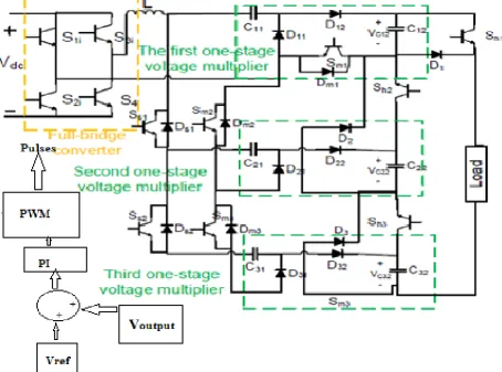
Figure 1. Suggests a schematic of to the proposed hybrid solid statepulsed powergenerator. As to in this discern demonstrates, HSSPPG shape is the completely modular besides absolutely bendy with comments controller. a topology of to the determine 1 includes an AC-DC converter, an entire-bridge converter, m modules of to the n-degree voltagemultipliers, 2m energy digital switches, besides the controller. Each voltagemultiplier consists of to the particularly lowvoltage diodes besides capacitors. It is the meant that Sm1.Sm2 …..Smm are charging switches besides Sh1.Sh2, ……Shm are pulsing switches. At a same time as a charging switches are closed besides the pulsing switches are operated, a capacitor can be charged. When charging switches are operated besides the pulsing of the switches are closed, an out-put to the voltage can be obtained from a subsequent equation,
…………. (1)
The out-put to the voltage is the determined with a resource of to the below factors:
The range of to the voltagemultipliers (m) The stage of to the voltagemultipliers (n)
[image:2.595.92.547.353.690.2]The manipulate of to the a general-bridge converter The out-put to the voltage of to the AC-DC converter The out-put to the voltage is the taken as the feed back is the compared with a particular reference values besides it is the given to a PI controller. After a tuning a signal is the nothing but the reference signal these are giving to a pwm generator. A generating pulses giving to a full bridge converter. An out-put to the will increases depending upon a reference value we given. An out-put to the will increase relying upon a reference fee we given. An out-put to the frequency may be controlled by using manner of to the controlling a full bridge converter besides a switching of to the charging besides pulsing switches. it's far off apparent that AC-DC besides full-bridge converters could be eliminated besides low voltage low frequency deliver right away connects to a voltagemultipliers. To in an example, however, an out-put to the voltage will become uncontrollable besides excessive out-put to the frequency could not be executed.
International Journal of Innovative Technology and Exploring Engineering (IJITEE) ISSN: 2278-3075, Volume-8, Issue-11S2, September 2019
III. REVIEW CRITERIA
SWITCHING MODES of to the PROPOSED SYSTEM
A) First mode switching
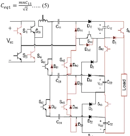
As shown to in a determine three, Sm1, Ss1 besides Ss2 are on besides D12.D22. besides D32 conduct. To in this mode, an inductor L besides capacitors of the series C11.C12.C21.C22.C31 besides C32 make a resonant circuit. On the behalf the simplicity, a capability of to the capacitors is the taken into consideration to be equal. A resonantfrequency can be acquired from a subsequent equations:
….. (2)
…….. (3)
…. (4)
As shown to in a determine three, Sm1, Ss1 besides Ss2 are on besides D12.D22. besides D32 conduct. To in this mode, an inductor L besides capacitors of the series C11.C12.C21.C22…, C31 besides C32 make a resonant circuit. On the behalf the simplicity, a capability of to the capacitors is the taken into consideration to be equal. A resonantfrequency can be acquired from a subsequent equations:
….. (5)
Fig 2. First mode switching operation
(B)Second mode switching
Position of to the powerswitches moreover diodes to in a mode are shown to in a Figure 4. D12, D22 besides D32 are turned off besides Sm2, Sm3, D11, D21, D31 Ds1 besides Ds2 are turned on. A resonantcircuit to in a mode includes an inductor ‘’L besides capacitors C11 besides C21. A resonant frequency is the equated as follows,
stage CDVMs Ceq1 can be obtained from a following equation:
….. (8)
[image:3.595.325.543.150.355.2]In this mode, on the behalf the a n-stage CDVM shown to in a figure 2, diodes D1, D3, … , D(2n-1) are to in an on-state besides D2, D4, …,D(2n) are to in a an off-on-state.
Fig 3. Second mode switching operation
(C)Third mode switching
For pulsing, Sm1, Sm2, Sm3, Ss1 besides Ss2 turned off besides Sh1, Sh2 besides Sh3 turned on. As shown to in a Figure 5, an output to the voltage can be obtained from a following equation,
…. (9)
Where VC12, VC22 besides VC32 are an out-put to the voltage of to the multipliers besides Vload is the load voltage. On the behalf a m modules, Vload is the calculated from following equation,
[image:3.595.56.278.369.602.2] [image:3.595.317.537.519.714.2]IV. SIMULATION RESULTS
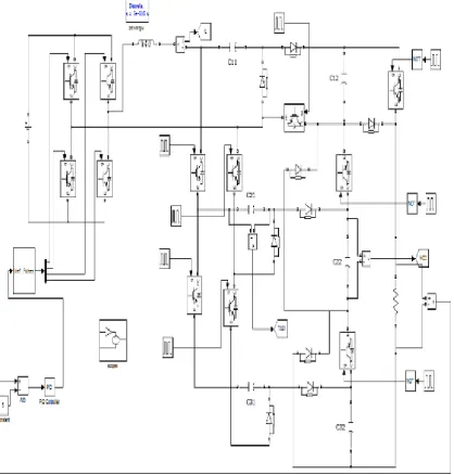
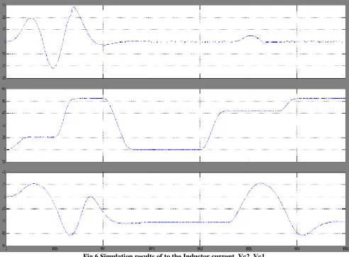
The figure 5. Shows proposed hybrid pulsed generator with feedback controller. Figure 9 shows an inductor current, a capacitor voltage, besides an out-put to the voltage. It's miles clean from inductorcurrent that a switching is the done to in a 0 modern without ripples. Due to a fact a voltage curve is the decided, a capacitorvoltage changes within a first cycle are exceptional from subsequent cycles due to a preliminary values of to the capacitorvoltage.
however on a forestall of to the any cycle, a capacitorvoltage reaches to 4Vdc besides an out-put to the voltage at a start of to the pulsing is a same to 12Vdc Compare to existing results a proposed results are improved depending upon a inputvoltage besides feedback controller. Besides to a proposed results there is the no ripples to in an inductor current.
[image:4.595.77.496.181.620.2]International Journal of Innovative Technology and Exploring Engineering (IJITEE) ISSN: 2278-3075, Volume-8, Issue-11S2, September 2019
Fig 6.Simulation results of to the Inductor current, Vc2, Vc1
V. CONCLUSION
In this paper, the hybrid stable statepulse powergenerator as the new pulsed electricity converter with PI controller has been proposed on the behalf the large pulsed power packages. This proposed topology is a combination of to the Marx topology besides voltage multiplier to in that is the modular besides flexible. A most out-put to the voltage of to the HSSPPG is the depending at a range of to the multiplier, a form of to the module, besides input voltage on an equal time because an out-put to the voltage may be changed effortlessly. A Proposed control method on the behalf the pulsed generator to reduce a switching loss besides to improve a performance. Simulations results been completed, besides an obtained outcomes confirm a right ordinary performance besides operation of to the proposed generator.
REFERENCES
1 S. Beebe, “Mechanisms of Nanosecond Pulsed Electric Field (NsPEF)- induced cell death in cells and tumors”, J. Nanomedicine Research, Vol.2, No.1, pp. 00016, 2015. 2 [2] B. Yu, S. Muenster, A.H. Blaesi, D.B. Bloch and W.M. Zapol, “Producing nitric oxide by pulsed electrical
”
liquid droplets in air”, IEEE Trans. Dielectr. Electr. Insul,Vol.22, No.4, pp.1866-71, 2015
4 N. Koutahzadeh, M.R. Esfahani and P.E. Arce,
“Removal of acid black 1 from water by the pulsed corona discharge advanced oxidation method”, J. Water Proc. Eng., Vol. 10, pp.1-8, 2016
5 R. Streubel, G. Bendt and B. Gökce, “Pilot-scale synthesis of metal nanoparticles by high-speed pulsed laser ablation in liquids”, Nanotechnology, Vol. 27, No. 20, pp.205602, 2016
6 W. Jiang, K. Yatsui, K. Takayama, M. Akemoto, E. Nakamura, N. Shimizu, A. Tokuchi, S. Rukin, V. Tarasenko, and A. Panchenko, “Compact solid-state switched pulsed power and its applications”, Proc.IEEE, Vol. 92, pp. 1180-1196, 2004.
7 T. Sakamoto, A. Nami, M. Akiyama, and H. Akiyama, “A repetitive solid state Marx-type pulsed power generator using multistage switch-capacitor cells”, IEEE Trans. Plasma Sci., Vol. 40, pp. 2316-2321, 2012.
8 L. Redondo, “A DC Voltage-Multiplier Circuit Working
as a High- Voltage Pulse Generator”, IEEE Trans. Plasma Sci.,Vol.38, pp.2725- 2729, 2010.
9 J. S. Won, D. H. Kim, C. G. Ro, K. S. Lee, K. S. Kim, and H. W. Lee, “Characteristics of the Forward type high voltage pulse power supply for a lamp type ozonizer”,
Proc. Power Convers. Conf., Osaka, Japan,
10 C. Wang and Q. H. Zhang, “EMI and its elimination in an integrated high voltage (12 kV) pulse generator”, 26th Annual Conf. of the IEEE In Indust. Electronic Society, Vol.2, pp. 1044–1049, 2002.
11 X. Tian, X. Wang, B. Tang, P. K. Chu, P. K. Ko, and Y. C. Cheng, “Special modulator for a high frequency, low-voltage plasma immersion ion implantation”, Rev. Sci. Instrum., Vol.70, No. 3, pp. 1824–1828,1999.
12 F. Wang, A. Kuthi, C. Jiang, Q. Zhou, and M. Gundersen, “Flyback resonant charger for a high repetition rate pseudospark pulse generator”, Power Modulator Conf. Sympos., pp. 85–88, 2004.
13 M. Giesselman and T. Heeren, “Rapid capacitor
charger”, Proc. Power Modulator Conf. Symp., pp. 146– 149, 2002.
14 S.H. Kim, M. Ehsani and C.S. Kim, “High-voltage power
supply using series-connected full-bridge PWM
converter for a pulsed power applications”, IEEE Trans. Dielectr. Electr. Insul, Vol. 22, No. 4, pp. 1937-44, 2015. 15 M. Rezanejad, A. Sheikholeslami, J. Adabi, “ Modular switched capacitor voltage multiplier topology for a pulsed power supply” , IEEE Trans. Dielectr. Electr. Insul, Vol. 21, No. 2, pp.635-43, 2014.
16 M. Acharya and P. Shrivastava, “Design and
development of a prototype 25 kV, 10 A long pulse Marx modulator for a high power klystron” , Rev. Sci. Instrum., Vol. 87, No. 2, pp.025114, 2016.
17 Y. Shen, W. Wang, Y. Liu, L. Xia, H. Zhang, H. Pan, J. Zhu, J. Shi, L. Zhang, J. Deng, “A compact 300 kV solid-state high-voltage nanosecond generator for a dielectric wall accelerator”, Rev. Sci. Instrum., Vol. 86, No. 5, pp.055110, 2015.
18 P.K. Srivastava, S.K. Singh, A.K. Sanyasi, L.M, Awasthi and S.K. Mattoo, “A 5 kA pulsed power supply for a inductive and plasma loads in large volume plasma device”, Rev. Sci. Instrum., Vol.87, No.7, pp.073501, 2016.
19 A.A. Elserougi, A.M. Massoud and S. Ahmed, “A Modular High-Voltage Pulse-Generator with Sequential Charging for a Water Treatment Applications”. IEEE Trans. Indust. Electronics, Vol. 63, No. 12, pp. 7898-7907, 2016.
20 T. Adachi, T. Arai, K. W. Leo, K. Takayama, and A. Tokuchi, “A solidstate Marx generator driven Einzel lens chopper”, Rev. Sci. Instrum., Vol. 82, p.083305, 2011. 21 J. Biela, D. Aggeler, D. Bortis, and J. W. Kolar,
“Balancing circuit for a a 5-Kv/50-Ns pulsed-power switch based on Sic-Jfet super cascode”, IEEE Trans. Plasma Sci., Vol.40, pp.2554-2560, 2012.
AUTHORS PROFILE
V.TAMILSELVAN, Professor, Department of Electrical and
Electronics Engineering, Karpagam college of engineering, Coimbatore,
Tamilnadu, Coimbatore
S.SIVA SUBRAMANIAN, Professor, Department of Electrical and
Electronics Engineering, Karpagam college of engineering, Coimbatore,