by
Lee Raymond Stirzaker
B.E., B.Sc. (U.N.S.W.)A Thesis Submitted to the
Australian National University
for the degree of
Master of Science
Page
A c k n o w l e d g e m e n t s i
P r e f a c e ii
A b s t r a c t iii
C H A P T E R 1 B INARY C O D I N G 1
Intro duetion 1
Synchronous Reception 2
A synchronous Signal ling 4
Transorthogonal Signalling 8
Biorthogonal S i g n alling 11
Discussion o f Results 12
Conelusion 14
A P P E N D I X 14
C H A P T E R 2 M U L T I L E V E L C O D I N G 17
Introduction 17
E r r o r Correction and Detection 18
A C K N O W L E D G E M E N T S
The work in this thesis was carried out at the Computer Centre, Australian National University, while sponsored by an A.N.U. Masters Scholarship.
I wish to acknowledge the guidance and fruitful interaction with my supervisor Dr C. K. Yuen who also made my stay most pleasant. Thanks must also go to my fellow students and members of staff who gave life and encouragement to this humble work.
P R E F A C E
The work in this thesis was carried out under the direction
of Dr C. K. Yuen.
All work in this thesis has appeared or will appear in two
joint publications with Dr Yuen.
All work in this thesis is my own unless otherwise
A B S T R A C T
This thesis looks at coded information transmission through a noisy channel.
The work of Viterbi [29] is extended to take into account phase asynchronous transmission and reception of the binary orthogonal, biorthogonal and transorthogonal code words in the presence of additive Gaussian noise. It is shown that asynchronous reception decreases the mean distance between code words while leaving their crosscorrelation unaltered. This results in the expressions for decoding error
probabilities similar to those of Viterbi with corrections added for the change in mean distance between code words with changes in asynchronism.
Also, a multilevel coding scheme proposed by Sankar and
Krishnamurthy [21] is reviewed and it is shown that their method can be improved for no loss of information rate. It is demonstrated that their use of generalised Hamming codes over multisymbol N-ary words has
C H A P T E R 1
BINARY CODING
Introduction
A classical set of codes is the orthogonal (Reed-Muller) codes and the trans- and bi-orthogonal codes derived from them. These codes have been studied for perfect synchronisation of transmitter and receiver. Here the effects of a partial synchronisation loss between transmitter and receiver are examined. The decoding error probability, using
optimal detection, is examined for various values of word length, signal-to-noise ratio (S/N) and asynchronous phase lead/lag. The model of the communication system uses an orthogonal set of Walsh functions (Reed-Muller code of maximal order) as the code set.
The communication system model used by Viterbi [29] is used in the following discussion. A sequence of code words, selected by the encoder of the transmitter from its set of m (=2n for n bit words) stored code words, is sent to the receiver over a noisy communication link. Each of the code words has a one-to-one relationship to an n-bit information word. At the receiver an identical set of code words is stored and an analog word-by-word correlation is performed on each incoming word in the sequence. The correlator with the largest (i.e. closest to unity) output is assumed to be the word sent. This form of detection has been shown to be minimum error optimal when the words are all equally likely, contain equal energies and are contaminated by additive white noise [16]. We are now interested in the decoding error probability given that the transmitter and receiver are not phase
functions are simply Reed-Muller codes of order N [19].
Synchronous Reception
Under simple orthogonal alphabet code transmission for no noise interference, all code words received remain orthogonal if transmitter and receiver are synchronised. For codes with other alphabets e.g.
0
transorthogonal and biorthogonal alphabets, their correlation properties change for asynchronous reception. Maximum likelihood detection is
performed with no information loss due to quantisation etc. and is minimum error optimal (in additive gaussian random white noise). However the analog correlation process must be clock synchronous as well as word synchronous as the alphabet correlation properties only hold when both synchronisms exist. Should word synchronism exist but clock (or phase) synchronism be absent the receiver correlators will have different means and covariances to their synchronous counterparts. Phase asynchronism has a unique effect on each alphabet.
For multichannel data transmission it is a simple matter to establish word and phase synchronism if a single channel can be spared. By transmitting code vectors over this special synchronising channel, say a pseudo-random (P-N) sequence having sharp correlation properties [7] which is transmitted synchronously with the data in other channels then when the code vectors in the synchronisation channel are synchronised in phase (as determined by the correlation being a maximum) then all other channels are synchronised too. This process is simple to implement at low capital cost.
Another method of word synchronisation is possible if all channels transmit a special synchronising sequence at intervals, say at the start
small loss of channel capacity. The pattern chosen must not be a pössible data word or any cyclic shift of a data word. Also the synchronising word must have only one possible synchronising point, that is, all possible
shifts of a pattern must not have another close point of synchronism which may be falsely induced by errors. The usual requirement on a synchronisa tion code is that the out-of-phase correlations be uniformly small , for all shifts of a code word with itself. The in-phase correlation is to be steeply peaked at unity. A more useful correlation property is to have a small but increasing correlation with approach of synchronism, thus
facilitating hardware realisation of synchronisation. An immunity to noise-induced errors in the received code must be incorporated.
The chief disadvantages of such synchronising schemes is that transmitter power must be used to transmit synchronising patterns which degrade the data rate and/or the data signal-to-noise ratio. The means of overcoming these problems is to have self-synchronising codes [23] , [3] .
One method of self-synchronising is available if orthogonal alphabet codes are to be used. This method known as the random source method, uses the leading digit of orthogonal sequences as an inherent marker. Such synchronising bits are known as Barker sequences [3], [8],
[17]. The method requires that the transmitter send all possible code sequences in the dictionary at random. The comma-free codes [24] overcome this problem. As code dictionaries become large these codes show rapid reduction in the synchronisation delay for large dictionaries (n > 4) over random source coding.
deletions is more difficult and references to codes to recover these is found in [13] and [1] .
Word (or framing) synchronism does not guarantee bit (or phase) synchronism. Phase synchronism may be achieved by the use of the correla tion properties of the code near phase synchronism. A hardware system, proposed by Harmuth [10], utilises the peaked correlation of Walsh
functions to obtain automatic synchronising. Slight variations in phase will result in increased erroneous receiver decisions during the interval
from sync, loss to its resumption. It is during this period that decoding error probabilities are of interest. It has been shown by Scholtz and Weber [22] that for phase incoherent communication the orthogonal alphabet has a global (over possible alphabets) extremum which is a local minimum with respect to error probability. Prior to this Balakrishnan [2] showed that for coherent communication the regular simplex codes (transorthogonal alphabet) were globally minimum error optimal [12] it has yet to be shown that the transorthogonal alphabet codes are globally minimum error optimal for the incoherent case.
In the following the effects of incoherence, signal-to-noise
ratio and alphabet size on error probability will be examined for orthogonal, biorthogonal and transorthogonal alphabets [26].
For comparison the error probability of n-bit words received synchronously and asynchronously bit-by-bit is included.
Asynchronous Signalling
bandwidth receiver and are decoded optimally by performing an analog correlation between each possible code word and the received code word. This process assumes that word and phase synchronism between the trans mitter and receiver exists. At the end of each correlation interval, the correlator with the largest output is selected as corresponding to the transmitted code function. A dictionary look-up procedure then identifies the n-bit word encoded at the source. Thus the probability of a decoding error being made is equal to the probability of the incorrect correlator being chosen at the end of each correlation interval. This is in turn dependent on the i-th correlator output being the largest compared to the other 2n-l possible correlator outputs given that the i-th code function was sent. Thus decoding error probabilities are calculable if the
continuous correlations of all code functions are known as well as the correlation properties of the noise. Phase asynchronism is then a
perturbation of the simple synchronous function correlations taking into account the overlap of the correlation window with the preceding or succeeding transmitted functions.
The stored functions of the model could be any orthogonal set of functions, binary, N-ary, or analog signals. Here we consider only binary orthogonal functions and in particular Walsh functions [20], [11]. Their properties are well defined [30], [20] and their recently discovered correlation properties [31] make this study possible.
A complete set of 21 Walsh functions stored at the transmitter and receiver permit n-bit information words to be exchanged unambiguously. All receiver stored functions are assumed to be exactly synchronised with
and the 2n-l th Walsh function is transmitted, the correlator output would be:
f1_2~n
wal (2n - l,t) wal (2*1 - 1, t + 2 n ) d t = 2 n - 1
J 0
This would render the 2n -l th Walsh function undetectable since at least one other function i.e. the 0 -th, would have a larger correlation, since the detector strategy always chooses the largest correlator output at unity
(normalised) time.
The probability that the i-th Walsh function will be correctly detected is the probability that the i-th correlator at the receiver has a value greater than all other correlators at unity time. This probability is expressed as:
.
r
P1 =
I
P(x.) P(X. > X., all j ^ i) d X .c l 1 3 l
j — 00
where p(X^) is the probability density function of the i-th correlator output X^, and P(X^ > X , all j ^ i) is the probability that X^ is greater
than all other correlators outputs X ^ , given the value of X^.
P ( X . > X., all j ^ 1) increases causing the error p r o b ability to increase.
Whe n the received signal lags the receiver stored functions by T
the m-th correlator output is:
X
m x (t) [ x .m d (t + 1 - T) + n(t + 1 - T)]dt +
x (t) [x. (t
m l - T) + n(t - T) ]dt
where the i-th function is the desired transmitted signal, it is preceded
by the j-th function and succeeded by the k -th function. The functions
have been normalised to give unity correlation for T = 0. The mean of the
m-th correlator is therefore
-T 1 — T
X
m x ( t ) x .(t + 1 - T)dt +m j x (t + T)x.(t)dtm l
In the case where the received signal leads the receiver stored functions ,.1-T
x (t) [x. (t + T) + n(t + T )]dt +
m l
I x (t) [x, (t - 1 + T) + n(t - 1 + T)]dt
1 m k
Jl_T
The m-th correlator m ean is
.1— T ,T
X
m x (t)x.(t + T) + m i X (t + 1 - T )x (t)dtm k
Jo
From the properties of Walsh functions [31] , x (t) = 1 for s
0 < t < 2 n . Also,
x (t) = +1 for s even s
- n g
for 1 - 2 < t < 1 and is represented as (-1) 1 , [31]. Thus the mean for
phase lag is:
X = T(-l)Dl + R ( m /i;T) m
and for phase lead
T (-1) 1 + R(m,i;T)
X is a linear function of incoherence time T since from [31], R(m,i;T) m
is a linear function of time as is T(-l)m i . The dependence of on T is
however non-linear.
As shown in the appendix, the variance is unaltered by the loss
of orthogonality, giving the following expression for error probability P"
1 - 7T- h exp ( - X2) II {h + h erf [x. + e(X. - X.)]}dX.
l . , l i n i
3=1
where
e = nST/(N /B) o
and
fx
erf(x) = 2TT \ exp(-y^)dy
Jo
This expression for P^ is a more general form of the Viterbi expression
[29] for orthogonal code error probability under synchronised reception.
The above model gives the same expression as [29] when T = 0.
Transorthogonal Signalling
The class of codes consisting of M functions which have correla
tion properties pij = ■ , i ^ j and pii = 1 are said to be transorthogonal
codes. These functions may be used in the system model in figure 1. This
class of code words is easily generated [34] as pseudo-random shift
register sequences [10] or as orthogonal binary sequences with the leading
conditions of receiption modified Walsh functions will be used to model transorthogonal code functions. The functions will be considered as being generated from the orthogonal set of Walsh functions with the leading interval 0 < t < 2 n suppressed.
The analysis of word detection error probability proceeds the same as for orthogonal code words. From the results [7], [2], P [STn/(N /B),p] =
e o
[(1— p )STn/(N^/B),0] and so the expression for transorthogonal word error probability is the same as for orthogonal code word communication with the
M
signal-to-noise ratio multiplied by — — (= 1-p). It can be seen that this M-l
factor;
M/M-l(= 2n/2n-l)
is only an effective modifier of the orthogonal word error probability for n small; as the number of bits, n, increases the error probability converges to that for orthogonal case. However, when the transmitter and receiver become unsynchronised, the orthogonal and transorthogonal word error probabilities do not tend to the same value, as the terms in the correla tion are altered by the leading bit of the transorthogonal word not being +1 all the time.
A set of 2n Walsh functions capable of encoding 2n n-bit data words can be transformed to a set of 2n transorthogonal functions by suppression of the leading interval 0 < t < 2 n .
We know from the above discussion that the word error probability is that for orthogonal words with the signal-to-noise ratio multiplied by the difference in correlator means. The mean value of the m-th correlator, given that the i-th transorthogonal function is the desired signal and it is preceded by the j-th function and succeeded by the k-th function, for
-n
.1
-n 2 +T
x (t ) x . (t - T)dt
m l I
From the properties of Walsh functions [31]
X (t) = + 1 m < 2n- ‘ m
_ n - 1 -1 m > 2
-n
< t „ -n+i 2 < 2
-n
For 1-2 < t < i
x . (t) = +1 j even 3
= -1 j odd
denoted (-1)
Therefore the first integral reduces simply to
T(-l) "(-I) t
The second integral can be rearranged into the form
.1 a - T
2 n+T
x (t)x. (t - T) dt m l
-n
x (T + T) x. (t) dT.
m l
Evaluating this by means of the known correlation R(a,b;0) and rearranging the form of the integral
r
J o " n
-1-T x (T+T) x . (T) dT
m l
-n
x (T+T) x . (T) dT - \ x (T+T) x . (T) dT
m i 1 m l
R (i,m;T) - (2 n-T) - T (-1) n .
Thus:
m j m
X = --- (t(-1) n (-l) 1 + R (i ,m ;T ) - (2~n-T) - (-1) n }. m 1-2 n
Through similar reasoning and decomposition the expected value of the m-th
— 1 - i k m X = — -- {R(m,i;T) - (2 n-T) - T(-l) n + T(-l) n (-1) }.
m 1-2 n
The third and final set of functions to be c o n s idered is the set
of binary biorthogonal functions, as defined in Viterbi [29].
Biorthogonal Signalling
n_ 2^
Detection of the 2 possible code words consisting of 2 binary
I"!"— 1
orthogonal functions and their 2 complements can be achieved using only n_
2 correlators. The practical consequence of this is only h alf the
number of hardware/software correlators are required for the number of
code words needed for orthogonal or transorthogonal coding.
In examining error probabilities of code words o n l y one half of
the set of code words is examined since the results for the complementary
subset of code words follows from the first b y symmetry. Decoding errors
involving the opposite subset are assumed to be negligibly small compared
with errors in the same subset, their distance being twice as far from
code words in the subset of interest.
The p r o b ability that the i-th orthogonal function, here modelled
as Walsh functions, is detected correctly, is the p robability that the
absolute value of the i-th correlator exceeds all other correlator values,
for some value of X^, m u l t iplied by its p robability density function
integrated over all positive values.
00
P1 = \ p(X.)P(X. ; |x. I > IX .I , j 1 i)dX.
c I 1 1 ' 1 1 1 j ' 1
n_ 2^
where j = 1,2, ... , 2 j ^ i . Thus P = 1
-0
1 - TT-h
(2 n-1 X.-X. e x p ( - y 2 )< II h [erf (y + - •*■)
-X, . j=l /20
P can be shown to be: c
X.+X. ) + erf (y + — ^— ^)]?dy
/20
)
where O is the variance of all correlator outputs and is a function of signal-to-noise ratio and bit number. The correlator means are functions of phase and index. This is a more general expression for error
probability than appears in [29]. The above expression gives to Viterbi's [29] at synchronism.
The mean of the m-th correlator output given that the i-th biorthogonal function is transmitted and phase lag of T is:
X m
rT 1
x (t)x . (t+l-T)dt + \ x (t)x.(t-T)dt
m 3 I m 1
J o JT
From the properties of Walsh functions x ( t ) = l , 0 < t < 2 n ,
rT
therefore the first integral becomes | x.(t+l-T)dt. Half of the possible
Jo
3values of x^(t+l-T) is +1, and half is -1. Therefore
X = ±T + R(i,m;T) m
For phase lead
X m
• 1 — T
X (t ) X,(t+T)dt +
m 1
r l
1-T
x (t)x, (t+l-T) dt
m k
Thus
X = R(m,i;T) ±T(-1) m
where the plus/minus signs account for the sign of the preceding and succeeding code word during the correlation interval.
Discussion of Results
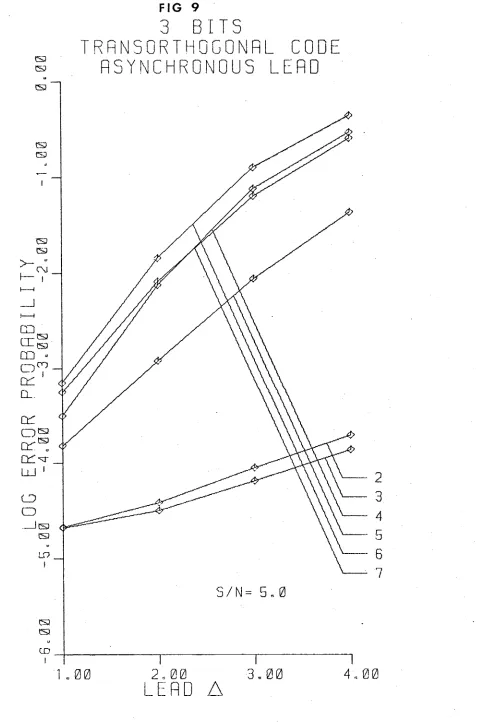
It was decided to compute P3 for a limited number of alphabet
bit words and four incoherence values (A = pM /6, p = 1,2,3,4). For completeness the error probability was also calculated for the synchronous case, p = 0. The signal-to-noise ratio was varied from 0.5 to 20. Some results are shown in figures 2 to 11 and the uncoded word error
probability in figure 12 for comparison.
In figures 2 to 5 the decoding error probability versus lag
asynchronism is plotted for four signal-to-noise ratios, when 3 bit binary messages are transmitted via an orthogonal set of eight Walsh functions. All Walsh functions from order zero to seven are plotted when their decoding error probability falls within the graph range.
Figures 6 and 7 show the same plot variables but S/N = 5. Figure 6 is of transorthogonal coded transmission while figure 7 is of
biorthogonal.
Figures 8, 9, 10 show vs A in phase lead asynchronous trans-e
mission when S/N = 5 for the three alphabet types.
Figure 11 shows the variation in decoding error probability of orthogonal codes with S/N for asynchronous lag constant.
The final figure, 12, is of the uncoded error probability for 1, 2, 3, 4 bit binary messages under various values of asynchronism.
The following general features were observed about the data
generated. As exoected, P"1 decreased for increases in S/N and decreases e
in incoherence,
A.
Graphs of log P^ versus S/N have a characteristicexponential decrease in P^ with increasing S/N. Their shape is an inverted half-parabola with P^ -* 1 for S/N -* 0 and P"1 -> 0 for S/N -* 00, for all
e e
j [29]. Also P^ decreased for increasing word size. The lower the S/N the more tightly grouped were the lines of P^ versus
A,
for all j. The lines had a steeper slope the higher S/N became; tending to P^ = 1 forA
large. In all alphabet types and word sizes the lines of P^ versusA
to form the code dictionaries had their error probability grouped accord ing to sequency in increasing as follows: 0/1/2/3/4,5/6,7/8,9/10,11,12, 13,14,15/. This corresponds to grouping by degrees [33], or according to the left-most "1" in the binary representation of j.
Conclusion
The results above conform to what is expected on intuitive grounds. Trends in can be readily determined from examining differences between
e
correlator means, for each j; large differences in mean result in low error rates while conversely small differences result in higher decoding error rates. We have examined the R-M codes of order n in terms of their Walsh function equivalent, for decoding error P^ in the presence of G-W
v e
noise and phase asynchronism. Individual codes will have different P^ performances as a function of incoherence because of the strong dependence on correlation.
APPENDIX
The covariance matrix of the correlator outputs for orthogonal, biorthogonal and transorthogonal alphabet codes is derived as follows:
If x (t) is the m-th stored receiver code word and the code word m
x^(t) is preceded by the word x+ (t) and succeeded by x (t) then the covariance matrix, in the presence of additive Gaussian stationary white
noise is
a =
<x x > - <x ><x >
mn m n m n
where X and X are the m-th and n-th correlator output functions,
m n
respectively.
Taking the case where the received signal lags the correlation window, the m-th correlator has output X at unity normalised time; where
m X is given by:
L
X = 1 x (t)x (t+l-A)dt +
m \ m
1
\ x (t)x.(t-A)dt + \
X m 1 ) .
A)dt + \ x (t)n(t)dt m
Since < n (t)> = O
<X > = \ x (t)x (t+l-A)dt + \ x (t)x.(t-A)dt
m 1 m j m l
J0 JA
A A
Ü
<X X > = 1 1 x (t) x (T)x+ (t+l-A) x+ (T+l-A)dtdT +
m n I 1 m n
0 ~ O 1 .1
U
x (t)x (T)x.(t-A)x.(T-A)dtdT +m n l l
A A' A .1
u
££
£(
x (t)x (T)x (t+l-A)x.(T-A)dtdT +
m n l
x (t)x (T)x (T+1-A)x.(t-A)dtdT +
m n l
x (t)x (T) <n(t)n(T)> dtdT.
m n
<X X > = <X ><X > + — — l x (t)x (t)dt,
m n m n 2 B \ m n
as <n(t)n(T)> Therefore
N
— — 6(t-T) for white, Gaussian random noise with zero mean.
a
mn x (t)x (t)dtm n (1 )
coherent correlation properties of the code. For orthogonal alphabet code words:
ö = — 6 (m-n) mn 2B
For biorthogonal alphabet code words:
a = — — 6 (m-n) m,n from same group mn 2B
O = - -r— 6 (m-n) m,n from different groups
mn 2B
For transorthogonal alphabet code words:
.N . . . -1
o ro(m-n) - M .
°mn = ii [~ --- =1-- 1
1 - M
C H A P T E R 2
MULTILEVEL CODING
Introduction
Binary data transmission may not always have the flexibility of encoding and manipulating afforded by some forms of non-binary coding. Compatibility of source and channel may also make the non-binary data
format attractive. Under these conditions and when some error control is desirable an encoding of the non-binary data becomes essential.
Various schemes proposed to date [4], [5], [6], [15], [28] operate on the non-binary data at the binary level and handle a limited class of errors. Non-binary transmission errors can be divided into two major
classes/ the small errors that result in the detected level being within one level of the transmitted one, or large errors involving a shift of many levels from the transmitted one.
The error detection/correction scheme examined in the following uses binary Hamming codes in their more general form [19]. In the work of Stirzaker and Yuen [25] we show that this method of Sankar Krishnamurthy
[21] recovers a more restricted set of errors than can be recovered by their use of these codes for no loss of information rate of the code used. We show that a wider class of errors can be corrected by performing Hamming coding on the binary form of the multilevel data, thereby deriving a
equivalent set of multilevel check symbols.
and applying a binary (n,k) Hamming code to this binary form by taking the k MSB's to make n-k MSB's of the check symbols. Each binary digit, down to the LSB is encoded in this way to form n-k multilevel check
symbols in binary representation. If a single error correcting Hamming code was used all single multilevel symbol errors are correctable because each symbol error falls into a block of n symbols and causes the erronoeus binary bit pattern of the particular symbol in error to appear in the m separate check equations.
An error may not produce errors in all m-bit positions leaving some check equations free to correct errors in other symbols, as only one bit error per bit check equation can be correctable. It is these spare check equations left over from a single symbol error which gives the added error correction power not present in the method of Sankar Krishnamurthy. Their method uses a single Hamming check equation (modulo 2m ) over the k multilevel symbols to produce the n-k check symbols. A single symbol is
correctable but further error control on the remaining symbols is impossible.
Error Correction and Detection
Sankar and Krishnamurthy [21] described a simple error detecting and correcting scheme using non-binary arithmetic Hamming codes [9]. Each n-symbol word consists of k modulo-m information symbols and n-k check symbols, where m is any base. Their method detected and corrected all single symbol errors.
information symbols, the formalism of which is given in Peterson and
Weldon [19]. Since these codes correct single errors it is possible for a multilevel single error correcting code to be simply derived using them, where arithmetic operations must then be performed in the new base. Thus a Hamming (7,4) single error correcting code can correct all single errors in a 7-symbol multilevel word by substituting the symbols for binary
characters. All parity syndromes must be zero (modulo
3
) for an absence of errors and syndromes cannot be unequal if the error is to be recoverable.It was found by Stirzaker and Yuen [25] that an improved error correcting facility existed if the symbols were converted from base 3 to binary and the parity checking applied to the individual bits of the binary representation. This requires that the base
3
be an exact power of 2 if accurate representation of the symbols in the set is to be obtained. This restriction is not often significant as binary alphabets are commonly used.%
By restricting the symbol set to binary powers, m = 2 , £• integral, using binary arithmatic manipulation, it becomes possible to correct all single symbol errors and a restricted set of multisymbol errors. For example consider the 7-symbol word whose symbol set is (0,1,2,...255), that is n = 7 and £ = 8, and has four information symbols, 209, 41, 149, 255 decimal. Their binary representation is 11010001, 00101001, lOOlOlOl, 11111111, respectively. Applying a (7,4) single error correcting Hamming code to the most significant bit (MSB) of the binary form of each symbol will generate the MSB of the three (n-k) check symbols. This is
repeated for the remaining bits forming the three 8-bit check symbols. They are 7 (00000111), 155 (10011011), 67 (01000011).
Cl = - (SI + S2 + S4) = 7 modulo 256 (1)
C2 = -(SI + S3 + S4) = 155 modulo 256 (2)
C3 = -(S2 + S3 + S4) = 67 modulo 256 (3)
If there is an error in any one of the seven symbols during transmission both methods will correct it. Let there be a -21 level error in the first
symbol. Then:
SI + S2 + S4 + Cl = 188 + 41 + 255 + 7 = 235 modulo 256
51 + S3 + S4 + C2 = 188 + 149+ 255 + 155 = 235 modulo 256
52 + S3 + S4 + C3 = 41 + 149+ 255 + 67 = 0 modulo 256
From these equations it can be seen that the first symbol SI is in error, since it is the only symbol to appear in (1) and (2) but not in (3). The correct value of SI can be obtained by rearranging (1):
SI = -(Cl + S2 + S4) = 209 modulo 256
Using the modified method parity check fails on bits 0, 2, 3, 5, 6 as shown:
188 10111100 SI
41 OOIOIOOI S2
149 10010101 S3
255 11111111 S4
7 OOOOOlll Cl
187 10<| L1011 C2
67 01000011 C3
the parity syndromes are:
where © denotes bitwise modulo-2 addition (exclusive-or). As before, since the first two syndromes are non-zero and equal the error occurred in the symbol Si. The corrected SI is obtained by bitwise exclusive-oring of si and SI:
si © SI = 10111100 © 01101101 = 11010001 = 209
The single error was of -21 levels. If another symbol had an error, say S2 had a +2-level error, then the first method [21] is incapable of correcting it as seen in the following:
SI + S2 + S4 + Cl = 188 + 43 + 255 + 7 = 237 modulo 256 SI + S3 + S4 + C2 = 188 + 149 + 255 +155 = 235 modulo 256 S2 + S3 + S4 + C3 = 43 + 149 + 255 + cr> II 2 modulo 256
Since all remainders are unequal an unrecoverable error has occured. The parity syndromes for the improved method are:
Si © S2 0 S4 © Cl = OllOllll 51 © S3 © S4 © C2 = 01101101 52 © S3 © S4 © C3 = 00000010
From the first two syndromes there has been an error in SI whose syndrome 01101101 an error of -21 levels. From the first and third syndromes there
is in S2 whose syndrome is 00000010 an error of +2 levels. Note that
188 10111100 SI
39 00100111 S2
149 10010101 S3
255 11111111 S4
7 00000111 Cl
155 10011011 C2
67 01000011 C3
the parity syndromes are:
si = SI © S2 © S4 © Cl = 01100011 s2 = SI © S3 © S4 © C2 = 01101100 S3 = S2 © S3 © S4 © C3 = OOOOlllO
which gives the syndrome for SI as OllOOOOO , the syndrome for S2 as OOOOOOlO and the syndrome for S3 as 00001100.
Note that there was also an error in Cl whose syndrome was 00000001 i.e. a -1 level error. The "'corrected" symbol set is:
SI = 11011100 = 220 S2 = 00100101 = 37 S3 = 10011001 = 153 S4 = 11111111 = 253 Cl = 00000110 = 6 C2 = 10011011 = 155 C3 = 01000011 = 67
The sign and magnitude of an error affects the above scheme significantly. If the error causes a small. change, say, from an even to
errors there may (in the worst case) be only one symbol error correctable because the symbol error has changed all m digits of the binary represent
ation (e.g. a o to 255 transition).
the use of binary Gray code for the conversion of multilevel symbols to digital form will convert small level errors to small numbers of bit errors. Moreover it has been shown by Yuen [32] that w Gray code bits are in error
greater than x. Since most errors are small and involve the LSB frequently it is advantageous if the following bit pattern reorganisation is used.
Gray code form and apply an (n,k) Hamming code/ as shown above, to give n multilevel symbols. A new set of n symbols is created by performing the
following shifting operations. Leave the rightmost bit (LSB) of the first symbol as the LSB of the first symbol of the new set. Let the second symbol be cyclically right-shifted one bit, the third shifted two bits and so on up to the n-th symbol which is right-shifted n-1 times. The
resulting new symbol set is then converted to a multilevel signal and transmitted. At the receiver the received symbols are converted to Gray code form and the opposite shifting performed. Decoding is then done to recover the corrected information symbols.
Using the above example, we see that the Gray code form of the information symbols is:
Since small level errors are most likely type of error to occur
Take k multilevel information symbols, convert them to binary
*
SI 10111001 209
*
S2 00111101 41
*
S3 11011111 149
*
the Gray coded check symbols are:
*
Cl 00000100 7
C2 11100110 187
C3 01100010 67
Reorganise the bit positions to form the new symbol set to be transmitted as shown in the following. The asterisk marks above show the new LSB after cyclic right shifting.
SI 10111001 209
S2 10011110 235
S3 11110111 165
S4 00010000 127
Cl 01000000 219
C2 00110111 55
C3 10001001 214
At the receiver each symbol received is converted into its Gray code form and shifted left once for the second symbol, twice for the third symbol up to n-1 times for the n-th symbol, the reverse of the encoding operation. Since LSB errors are the most likely these are now distributed across all bit positions, placing them all in separate bit parity equations allowing correction. Let there be a -1 level error in Si and S2, when they reach the receiver in coded form. The received levels and their Gray code equivalent for the above case of n (= 7) symbols is shown below:
SI 10111000 208
S2 10011111 234
S3 11110111 165
S4 00010000 127
Cl 01000000 219
C2 00110111 55
Performing the cyclic left shifting:
SI 10111000 208
S2 00111111 42
S3 11011111 149
S4 10000000 255
Cl 00000100 7
C2 11100110 187
C3 01100010 167
that the parity syndromes are:
si = SI © S2 0 S4 0 Cl = 00000011 s2 = SI 0 S3 0 S4 © C2 = 00000001 S3 = S2 0 S3 © S4 © C3 = 00000010
From which we see that bit errors exist in SI and S2 and they are in the LSB of Si and the next most significant bit of S2, respectively. Recovery of the corrected symbols is obtained by bitwise exclusive-or ing of the error syndromes with si and s2 respectively. The syndromes are 00000001 and 00000010.
It can be seen that our method has the advantage over the scheme of [21] in that modulo -2 arithmetic is simpler and consequently cheaper to implement and because the bit operations involve no carrys and all operations are in parallel it is quicker.
Other multi-level coding schemes have been suggested which detect and correct a variety of error patterns [14], [6]•
Simple schemes exist for correction of small errors. One such is the adding of a parity check on each LSB. An error in the LSB is detected in the parity equations and the correct level is obtained by
level the correct level is the one below. To increase the code rate each LSB of k n-ary symbols, k < n, can be converted into an n-ary check
symbol by an (n,k) error correcting code which corrects k + 1 errors. This allows all single level errors in k + 1 data symbols (k information + 1 check) to be corrected. The code rate improves from 1/2 (1 information symbol + 1 check symbol) to k/k+1 (k information symbols +1 check symbol).
For the case where more than one level errors are likely more digits must be parity checked. Fewer digits need checking if Gray coded levels are used. A table of level errors versus Gray code bit errors is shown below.
Levels Gray
error bits
1 1
2 2
3 3
6 4
12 5
32 6
43 7
86 8
R E F E R E N C E S
[1] Bahl, L.R. and Jelinek, F . , "Decoding for Channels with Insertions, Deletions and Substitutions, with Applications to Speech Recogni tion", IBM Research Report, April 10, 1974.
[2] Balakrishnan, A.V., "A Contribution to the Sphere-Packing Problem of Communication Theory", Journal of Mathematical Analysis and Applications, 3_, 458-506, 1961.
[3] Barker, R.H., "Group Synchronising of Binary Digital Systems", in Communication Theory, London : Butterworth, 1953.
[4] Elspas, B., "A Note on P-Nary Adjacent-Error-Correcting Codes", IRE Trans, on Inf. Th., 13-15, 1960.
[5] Farrell, P.G. and Al-Bandar, Z . , "Multilevel Single Error-Correcting Codes", Electronics Letters, 10, no. 16, 347- , 8 August, 1974.
[6] Golay, M.J.E., "Notes on the Penny-Weighing Problem, Lossless Symbol Coding with Non-Primes, Etc.", IRE Trans, on Inf. Th., 103-109, September 1958.
[7] Golomb, S.W., "Digital Communication with Space Application", Prentice-Hall, 1964.
[8] Golomb, S.W. and Scholtz, R.A., "Generalised Barker Sequences", IEEE Trans, on Inf. Th., It-11, no. 4, 533-537, 4 October, 1965. [9] Hamming, R.W., "Error-Detecting and Error-Correcting Codes",
Bell. Syst. Tech. J., 29, 147-160, April 1950.
[10] Harmuth, H.F., "Transmission of Information by Orthogonal Functions", 2nd Edition, Springer-Verlag, 1972.
[11] Jain, P.C., "Problems of Synchronisation and Non-Linear Distortion and their Effects on Detection of Walsh Functions", Proc.
International Sym. on the Applications of Walsh Functions, 1973. [12] Landau, H.J. and Slepian, D . , "On the Optimality of the Regular
Simplex Code", Bell Sys. Tech. J., £5, 1247-1272, October 1966. [13] Levinstein, V.I., "Binary Codes for the Correction Insertions,
Deletions, and Change of Symbol", Dolk. Akad. Nuak Ukr. SSR., 163, 845-848, 1965.
[14] Lee, C.Y., "Some Properties of Nonbinary Error-Correcting Code", IRE Trans, on Inf. Th., 77-82, June 1958.
[16] Middleton, D. and Van Meter, D . , "Detection and Extraction of Signals in Noise from the Point of View of Statistical Decision Theory", J. Soc. Ind. and Appl. Math., _3, pt. 1, 192-253,
December, 1955; 4_, pt. 2, 86-119, June 1956.
[17] Moharir, P.S. and Selvarajan, A., "Systematic Search for Optical Barker Codes with Minimum Length", Electronics Letters, 10, no. 12, 245-246, 13 June, 1974.
[18] Nuttall, A.H., "Error Probabilities for Equicorrelated M-ary Signals Under Phase-Coherent Phase-Incoherent Reception", IRE Trans. Inf. Th., 305-314, July 1962.
[19] Peterson, W.W. and Weldon, E.J., "Error-Correcting Codes", MIT Press, 2nd edition, 1972.
[20] Paley, R.E.A.C., "A Remarkable Series of Orthogonal Functions", Proc. Lond. Math. Soc. 3_4, 241-279, 1932.
[21] Sankar, P.V. and Krishnamurthy, E.V., "Error Correction in Non binary Words", Proc. IEEE, 61, no. 4, 507-508, April 1973.
[22] Scholtz, R.A. and Weber, C.L., "Signal Design for Phase-Incoherent Communication", IEEE Trans, on Inf. Th., It-12, no. 4, 456-463, October 1966.
[23] Scholtz, R.A., "Codes with Synchronisation Capability", IEEE Trans, on Inf. Th., It-12, no. 2, 135-142, April 1966. [24] Stiffler, J.J., "Synchronisation of Telemetry Codes", IRE Trans,
on Space Electronics and Telemetry, set-8, no. 2, 112-117, June 1962.
[25] Stirzaker, L.R. and Yuen, C.K., "A Note on Error Correction in Nonbinary Words", Proc. IEEE, October 1974.
[26] Stirzaker, L.R. and Yuen, C.K., "Effects of Partial Synchronisation Loss on Coded Communication, to appear.
[27] Ullman, J.D., "Near-Optimal, Single-Synchronisation N-Error-Correcting Code", IEEE Trans, on Inf. Th., It-12, no. 4, 418-424, October 1966.
[28] Ulrich, W . , "Non-Binary Error Correcting Codes", Bell System Technical Journal, 1341-1388, November 1957.
[29] Viterbi, A.J., "On Coded Phase Coherent Communications", IRE Trans, on Space Electronics and Telemetry", Set-7, 3-14, March 1961.
[30] Walsh, J.L., "A Closed Set of Normal Orthogonal Functions, Am. J. Math., 45_, 5-24, 1923.
[31] Yuen, C.K., "Interchannel Interference in Walsh Multiplex Systems", IEEE Trans, on Comm., Com-22, no. 2, 255-261, February 1974.
Yuen, C.K., "The Separability of Gray Code", IEEE Trans, on Information Theory, 20, 668, 1974.
[33] Yuen, C.K., "Upper Bounds on Walsh Transform", IEEE Trans: on Comp., C-21, 1273-1280, December 1973.
[34] Yuen, C.K. and Kitai, R . , "Walsh Function Generators", in
C ü K S E -L A Teas
[image:35.552.73.511.60.776.2]O R T H O G O N A L C O D E
A S Y N C H R O N O U S
L A G
or. ^
i - _3
B I T S
O R T H Q G O N R L C O D E
A S Y N C H R O N O U S
L A G
tSJ <•
O R T H O G O N A L C O D E
A S Y N C H R O N O O S
L A G
CD
-! .
00
ca
S)
(S3
S> (S3
I
m'
er
co
S3
S3
O 7
-co
CL
CO
O s
o r ^
C O S - _
LO 1
CD
0
—I s
S3
LO
I
S3 S3
CD
3
B [ T S
O R T H O G O N A L C O O E
R S Y N C H R 0 N 0 0 5
L A G
1. 00
2„ 00
L A G A
T R R N 5 0 R T H 0 G G N R L C O G E
R S Y N C H R O N O U S
L R G
CD
[image:40.552.68.517.46.714.2]l
o
g
e
r
r
o
r
p
r
o
b
a
b
i
l
i
t
y
.0
0
-5
.0
0
-4
.0
0
-3
.0
0
-2
.0
0
-1
.0
0
0
.0
0
3
B I T S
B I O R T H O G O N A L CODE
A S Y N C H R O N O U S
LRG
1 . 0 0
O R T H O G O N A L C O D E
A S Y N C H R O N O U S L E A D
tn •
fY ' ^
2 , 0 0
L
E R G ZZ
tSJ
3
BI TS
T R R N S O R T H O G O N R L CODE
R S Y N C H R O N O U S L E R D
or .
c
t s
S)
ED
1
.
00
2 , 0 0
L E A D A
[image:43.552.58.536.52.775.2]B I 0 R T H 0 G 0 N R L C O D E
R S Y N C H R O N O U S L E R D
2 . 0 0
[image:44.552.73.517.54.800.2]3
B I T S
O R T H D G O N R L C O D E
R S Y N C H R O N O U S
L R G
- 1 . 0 0 0 . 0 0 i . 0 0 2 . 0 0
L O G S I G N R L / N O I S E
3
B I T S
O R T H D G O N R L C O D E
R S Y N C H R D N O U S
L R G
I---- OJ
- 1 . 0 0 0 . 0 0 i . 0 0 2 . C
[image:45.552.49.539.65.803.2]S
S
SI
I
Si
> - s I— oo
CQ CL isi
QQ^
O n
Cd 1
Q_
Cd
O s C d ^
Cd^-UJ '
CD
a
__I Si Si
LO
Si
Si
S > - ® i---- CM
CQ C E s i
CO^ .
O n cd. 1 Q_ Cd a s ^ s Cd *3 LÜ 1 a a
_ J s s
A = - 2
ss ss
- 1 . 0 0 0 . 0 0 i . 00 2 . 0 0 - 1 . 0 0 0 . 0 0 i . 0 0 2.
U N C O D E D W O R D S
®
( A S Y N C H R O N O U S
I— c \j
BI TS
a co
BI TS
BI TS
BI TS
__I s