This is a repository copy of
A Modular Multilevel Flying Capacitor Converter-based
STATCOM for Reactive Power Control
.
White Rose Research Online URL for this paper:
http://eprints.whiterose.ac.uk/100859/
Version: Accepted Version
Proceedings Paper:
Nwobu, CJ orcid.org/0000-0003-0502-9841, Efika, IB, Oghorada, OJK et al. (1 more
author) (2015) A Modular Multilevel Flying Capacitor Converter-based STATCOM for
Reactive Power Control. In: Power Electronics and Applications (EPE'15 ECCE-Europe),
2015 17th European Conference on. EPE 15 ECCE-Europe, 08-10 Sep 2015, Geneva,
Switzerland. IEEE . ISBN 978-9-0758-1522-1
https://doi.org/10.1109/EPE.2015.7309085
(c) 2015 IEEE. Personal use of this material is permitted. Permission from IEEE must be
obtained for all other users, including reprinting/ republishing this material for advertising or
promotional purposes, creating new collective works for resale or redistribution to servers
or lists, or reuse of any copyrighted components of this work in other works.
[email protected] https://eprints.whiterose.ac.uk/ Reuse
Unless indicated otherwise, fulltext items are protected by copyright with all rights reserved. The copyright exception in section 29 of the Copyright, Designs and Patents Act 1988 allows the making of a single copy solely for the purpose of non-commercial research or private study within the limits of fair dealing. The publisher or other rights-holder may allow further reproduction and re-use of this version - refer to the White Rose Research Online record for this item. Where records identify the publisher as the copyright holder, users can verify any specific terms of use on the publisher’s website.
Takedown
If you consider content in White Rose Research Online to be in breach of UK law, please notify us by
A Modular Multilevel Flying Capacitor Converter-Based STATCOM for
Reactive Power Control in Distribution Systems
C.J. Nwobu, I.B.Efika, O.J.K Oghorada and L. Zhang
UNIVERSITY OF LEEDS
School of Electronic and Electrical Engineering, University of Leeds
Leeds, United Kingdom
Tel.: +44 / (0)
–
113 343 2000
Fax: +44 / (0)
–
113 343 2032
E-Mail:
[email protected]
,
[email protected]
URL:
http://www.leeds.ac.uk
Keywords
«Multilevel converters », «Pulse Width Modulation (PWM) », «STATCOM », «
Voltage Source
Converter (VSC)
», «Reactive Power».Abstract
This paper presents a simulation study for a built prototype of modular multi-level flying capacitor cascade converter as a STATCOM. The converter modulation scheme applied is based on Phase Shifted PWM and the two scenarios which require compensation are investigated to verify this topology. The two scenarios are PCC voltage regulation and unity power factor correction through reactive power compensation. Simulation results verify the performance of the chosen topology.
1.
Introduction
The STATCOM, as an established FACTs device for providing reactive power compensation and voltage regulation for power networks, is in increasing demand for distribution systems. Major changes are posing challenges to the stability and power quality of distribution networks, notably the growth in distributed generation, particular in the form of widespread installations of grid connected PV panels and accelerated use of electric vehicles, requiring battery charging stations to provide redundant power supply. Consequently, excessive and often bidirectional current flow in lines and transformers, causes severe voltage fluctuation, and waveform distortion. In combination with these is the presence of predominantly reactive and non-sinusoidal load due to unprecedented widespread use of power electronic based equipment by industrial consumer. The consequent current and voltage harmonics have detrimental effects, including electro-magnetic interference (EMI), overloading the cables and may even result in voltage swell or drop proportional to the load current, interconnected line impedance and frequency. Also, the presence of reactive current on the line results in low power factor and reduced efficiency. STATCOM offers effective solution to some of these problems.
Recent development in Modular Multi-level Cascaded Converters (MMCC) makes the topology an enabling technology for STATCOM in medium and high voltage network applications [1-4]. The main advantage of the modular structure is in allowing the circuit to be scalable to work at any voltage level, so that a transformer may not be needed. With lower voltage stress across its switches and lower switching frequencies, the topology offers lower power losses and higher converter efficiency whilst generating good quality waveforms. MMCC-STATCOM schemes implemented in practice are based on the Cascaded H-bridge MMCC topology [5-7]
This paper presents a STATCOM built on a variant of the MMCC, the Modular Multilevel Flying Capacitor Converter (MMFCC). In this form, each module is a basic single-phase three-level full-bridge flying capacitor converter which can generate three voltage levels (0, ±VDC/2, ±VDC) and can be
individually controlled [8-11]. For an MMFCC-based STATCOM the main challenge is to achieve flexible and high performance line voltage control and reactive power compensation whilst maintaining module and floating capacitor voltages balanced. In this work a Unipolar Phase Shifting PWM modulation scheme is discussed as the chosen switching control method which can achieve natural floating capacitor voltage balance. Subsequently an MMFCC can be treated as for a cascaded H-bridge converter but having more voltage levels per module. Such a topology may be applied as a STATCOM for reactive power control in a power system. The paper will show that module capacitor voltage can be balanced by controlling the average voltage of phase limbs without concerning about the floating capacitor voltages. Simulation results of this STATCOM for voltage control of a small power network are shown giving desired responses and discussed.
2.
MMFCC and Phase Shift PWM Control
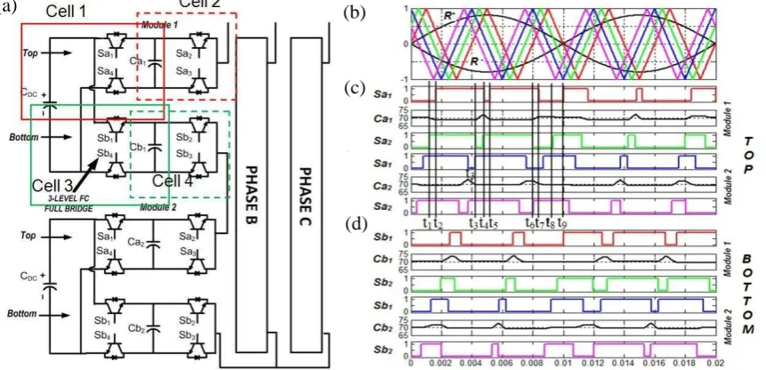
The phase limb of an MMFCC comprises a chain of three-level flying capacitor full-bridge converter as the basic module. Each module, as shown in Fig 1a, having two floating capacitors Ca and Cb and
an outer DC Bus capacitor CDC, is capable of synthesizing a total of 5 voltage levels, ±VDC, ±VDC/2,
and 0 volt. For three phase applications the three-phase limbs can be in either star or delta connection which may be referred to as Single Star Flying Capacitor Cell (MMC-SSFCC) and Single Delta Flying Capacitor Cell (MMC-SDFCC) following the nomenclature presented by Akagi [5]. For this work an MMCC-SSFCC consisting of six modules is used as shown in Fig 1a. Each phase limb comprising of two modules synthesise a total of 9 voltage levels (±2VDC, ±1.5VDC, ±VDC, ±0.5VDC, 0 volt). Recent
work has investigated using this topology to function as a STATCOM in a medium voltage network [8].
One of the key issues when using a MMCC-SSFCC as a STATCOM relates to the fluctuations of capacitor voltages. With two floating capacitors in each module, an ideal switching scheme should be one which can maintain these voltages balanced, so that the modules can be treated as H-bridges but with the advantage of having more voltage levels. The unipolar phase-shifted PWM (PS-PWM) scheme is considered most suitable as it can ensure natural balance of the floating capacitor voltages. As is known a unipolar scheme uses two reference signals which are anti-phase to each other, and these determine the switching actions of two legs in a two-level H-bridge so that they do not switch simultaneously. When using the unipolar PS-PWM for an MMFCC, each 3-level FC module also has two legs, labelled top and bottom in Fig. 1(a). The top leg is controlled according to the positive reference signal R+ and comprises two cells: cell 1, consisting of CDC – Ca – Sa1 – Sa4 and cell 2
containing Ca– Sa2– Sa3. Similarly the bottom leg, comprising cell 3 containing CDC– Cb– Sb1– Sb4
and cell 4 containing Cb– Sb2– Sb3, is switched according to the negative signal R- .
The two reference signals are compared with four triangular carriers phase shifted by a constant angle
C= /4 between each other. The interceptions of each of them with the positive reference R
+
generate four identical but phase shifted pulse trains as shown in Fig. 1(c); these are for driving four complementary switches in cell 1 and cell 2 in the top legs of the two modules. Similarly the interceptions of the same four carriers with R- are used to control the four cells in the bottom legs. In
and positive peak phase voltage that an MMFCC can generate. For example for three modules per phase, the number of distinct voltage levels is six, hence six carriers are required.
Applying four switching pulse trains to control the four cell switches of a single module, the natural floating capacitor voltage balances are maintained within a cycle. This can be illustrated using cell 1 in the top leg of module 1 as an example. The PS-PWM waveforms shown in Fig. 1 (b) have reference and carrier frequencies of 50Hz and 250 Hz respectively, giving a frequency modulation index mf =5.
The floating capacitor is set as 5mf and 70V, while the module capacitor CDC is set as a DC supply
with 140V.
Fig. 1: (a) MMFCC-STATCOM Power Circuit diagram, (b) Reference and Carrier waveforms for PS-PWM Modulation Technique (c) switching pulses for top cells and (d) bottom cells of two modules.
The top two switching pulse trains given in Fig. 1(c) are for control of Sa1 and Sa2 in cell 1. At time t1 a
pulse is applied to turn on Sa2, setting the module top leg terminal voltage to +VDC/2; Ca1 discharges
hence its voltage level falls. This continues until t2 when Sa1 is turned on.During t2 to t3 the top leg
terminal voltage rises to +VDC; Ca1 is neither charging nor discharging, so its voltage stays at the lower
discharged level. At t3 Sa2 turns off while Sa1 stayson; this makes the terminal voltage return to +VDC/2
as during t1 - t2, but the switching state is different. In this case the load current path enables Ca1 to be
charged, and hence its voltage rises above the nominal level. In the same way, inspecting the switching states and capacitor voltage changes as shown for the rest of the half cycle from t3 to t9.
Likewise for the negative half cycle the switching actions are reverse symmetrical to their positive counterparts. Thus provided the same reference signal is used the voltage for Ca1 is always balanced.
This clearly applies to all the floating capacitors in the other modules.
The above discussion shows that, using PS-PWM control, the MMFCC can be regarded as an H-bridge converter in the steady-state, and hence the consideration of voltage balance control can be mainly focused on the voltages across the module capacitors rather than the floating capacitors. It is also important to note that the unipolar PS-PWM scheme results in equal utilization of the switching states. Thus the voltage stress and switching losses are shared evenly across the switching devices. Clearly when more modules are added in the chain while retaining the same switching frequency per module per cycle, the effective output voltage harmonic frequency increases. This is as a result of the increased number of carrier waves becoming more tightly packed together and thus duty ratio across the unit cells almost identical.
The unipolar switching action on the 4 unit cells in each 3-level FC module results in the harmonics in
the output voltage waveform to appear at 4 times the actual cell switching frequency
fh4fs
. Each(a) (b)
(c)
[image:4.595.76.507.195.403.2]additional 3-level FC module stacked per-phase pushes this further the spectra by a factor of
n
, hence the harmonic frequency would bek m n j
h ( 4 f) (1)
where,
h
= harmonic order,j
= harmonic position, mf= frequency modulation index,k
= index ofside band. Fourier spectrum analysis of the converters output voltage waveform is shown in Fig. 2
A comparison of total harmonic distortion (THD) at various mf and ma is shown. The THD is
primarily governed my ma and varies slightly for various values of f
[image:5.595.139.447.247.412.2]m . Based on this result, a feasible range in this investigation to maintain good harmonic characteristics would be a modulation frequency index mf 3 and modulation amplitude index within0.7mf 0.9.
Fig. 2: Fourier Spectrum Analysis of Voltage waveform
3.
Control Scheme for an MMFCC-based STATCOM
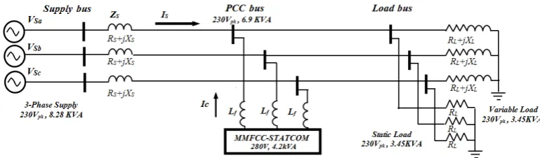
The power network is rated at 230V, 8.28 KVA, 50Hz. The supply side of the distribution line is modelled as a pi-section equivalent distribution line made of aluminium and of length 2.5km (0.5 ,
5mH, 10nF per km) corresponding to a reactance of 1.57 Ω. The X/R ratio (short circuit ratio) is
greater than 1 showing that the line reactance contributes more to voltage drop across the distribution line. Also connected at the PCC are two loads, a variable load with a power factor of 0.8 drawing a reactive power of 2.07 kVAR, and a static load drawing an active power of 2.07 kW. An R-L filter is used at the converter side to reduce the harmonics due to converter switching. The choice of filtering inductance is based on IEEE 1547 specifications [12-14] which recommends about 30% of the total
load impedance. A 20 Ω damping resistor is used to reduce the resonance of the floating capacitors
which in this case have no feedback. Each module bus capacitor, CDC, and the module flying
capacitors (Ca, Cb) set as 0.26mF and 0.13mF respectively.
[image:5.595.104.489.609.722.2]Crucial requirement for the control scheme is to maintain constant module voltages and ensure that load disturbances/transient changes are maintained within limits. Based on this, the closed loop system comprises the following compensator controllers
• Capacitor DC Bus balancing control,
• PCC voltage regulation control, and
• P+I Current Control
3.1 Capacitor DC Bus Balancing Control
The DC-Bus voltage in each module should ideally be maintained at its required level by its outer module capacitor, but load and switching pattern variations may cause it to fluctuate. A DC-bus voltage controller is, therefore, required to ensure that the DC voltage across every module remains at the specified DC value. The block diagram of the DC bus voltage controller is shown in Fig. 4a. The scheme assumes that the three phase voltages at the PCC-bus are balanced and the STATCOM delivers balanced compensation currents. Hence the controller takes the average value of the three phase limb voltagesVdc(a vg)as the controlled signal, which is calculated as
3 6 1 ) ( ) (
i i M dc a vg dc VV (2)
where,
i
= number of modules and in this study only six modules are used, VdcM(i)representsDC-voltage across each individual module.
The reference DC-bus voltageVdcr efis compared with Vdc(a vg)and the error is passed onto the P+I
regulator in order to generate the d-component of the controlled current vector.
The use of PS-PWM modulation scheme has enabled natural floating capacitor balances, and hence they do not require any feedback control. Using [15], the proportional and integral gain kp and ki
were chosen as 10, 500 respectively.
3.2 PCC Voltage Regulation Control
The PCC Voltage regulation loop aims to maintain the PCC voltage at the required level given as
ref AC
V . A simple P+I controller is used to generate reactive current element Iqr ef based on the
difference between the PCC voltage and the desired AC voltage set pointVACref. The feedback
variable VPCC represents the measured magnitude of the AC voltage at the PCC calculated by
resolving the three phase voltage vector into d and q components as shown in (3).
2 2 pcc q pcc d
PCC V V
V (3)
The proportional and integral gains were chosen as 9, 500 respectively.
3.1 P+I Current Controller
The compensation current generated by the STATCOM provides a means of regulating the voltages at the two terminals; at the AC side to influence reactive power flow and at the converter DC side to compensate the converter losses. In Fig. 4c, the d and q componentsIdconv, Iqconvof STATCOM
current vector are measured from converter bus, whilst theIdref,Iqr ef components are the required
d-q current values to be supplied by the converter. They are compared and the error signals are applied to the PI controllers respectively. The d-q output signals from the P+I controllers are combined with the coupling terms,
Lf and
Lf respectively to form the d-q elements of reference voltage vector`
Fig. 4: (a) High level system control diagram, (b) Capacitor DC bus voltage regulator control (c) AC voltage regulator control (d) Compensation current controller
4.
Analysis and Simulation Results
Matlab Simulink was used to investigate the systems configuration outlined earlier and two different scenarios were simulated. Firstly, reactive compensation of voltage drop realised at the PCC of the distribution line. Next, unity power factor correction at the PCC when the variable load draws a reactive power of 2.07 KVA. Total simulated time is 3 seconds, converter switching frequency = 750Hz. Converter start/charge-up was completed at approximately 0.04 seconds (2 fundamental cycles) while complete system steady state was achieved at approximately 0.08s (4 Fundamental cycles). All investigations are performed under balanced conditions as such; only single phase representation (Phase A) waveforms are shown for clarity.
4.1 PCC Voltage regulation based on MMFCC-STATCOM
At the start of the simulation (0 < t < 1), a small static load is connected and draws an active power of 2.07 KW causing a voltage drop of 1.6 V across the line. At time interval (1 < t < 2), a larger static load is switched in addition drawing an active power of 3.45KW corresponding to a voltage drop of 4.3V. At the time interval (2 < t < 3), the large static load is switched off and the system returns to back to a voltage drop of 1.6V. The converter compensates by injecting reactive power throughout the whole simulation. The voltages and currents have been normalised to per unit values by dividing by their respective base values.
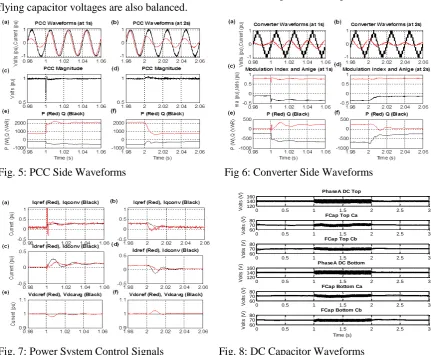
Fig. 5 (a)-(f) shows the PCC side waveforms. Within the time intervals (1 < t < 2) and (2 < t < 3) the STATCOM supplies reactive power (capacitive) in order to return the voltage to its nominal value. This operation of the STATCOM converter causes the magnitude of the PCC voltage to remain the same as shown in (c)-(d). The reactive power at PCC hence is -365 VAR and -175 VAR respectively is as shown in (e)-(f). The power factor is no longer unity as expected for PCC voltage regulation and the response of the converter to generate reactive power is fast at 3ms.
Fig. 6 (a)-(f) shows the converter side waveforms. Within the time intervals (1 < t < 2) and (2 < t < 3) the STATCOM supplies a capacitive current (+90o) of 1A and 3.5A respectively in (a)-(b). This operation of the STATCOM converter (1 < t < 2) causes a modulation index decrease from 0.81 to 0.78 and increase in the converters angle from -0.11 rads to -0.35 rads as shown in (c)-(d). The reactive power generated from the converter is -685 VAR and -235 VAR respectively is as shown in (e)-(f).
(a)
(b)
[image:7.595.71.526.69.266.2]Fig. 7 shows the resulting control signals at the different control blocks and as shown voltage regulation achieved between the time intervals (1 < t < 2) and (2 < t < 3). The response times are fast seen to 40ms and 30ms respectively.
[image:8.595.73.505.184.539.2]Fig. 8 shows the DC bus balancing across the capacitors of a single phase. The DC Bus voltage controlled to a nominal value of 140 V across the 0.26 mF capacitor. At the time interval (1 < t < 2), the module bus dc capacitors experienced a higher voltage variation of 7 V (±0.05%) while the flying capacitors experienced a deviation of approximately 3.5 V (±0.05%). The ripple are hence maintained within (± 10%) its nominal value. As noticed natural balancing occurs using PSWPM and the inner flying capacitor voltages are also balanced.
Fig. 5: PCC Side Waveforms Fig 6: Converter Side Waveforms
Fig. 7: Power System Control Signals Fig. 8: DC Capacitor Waveforms
3.1 Unity Power Factor Correction based on MMFCC STATCOM
At the start of the simulation (0 < t < 1), the static load is connected and draws an active power of 2.07 KW. At time interval (1 < t < 2), a variable inductive load in addition is switched in absorbing a reactive power of 690 VAR . At the time interval (2 < t < 3) , the variable load is switched off and the system returns to normal. The converter compensates by injecting reactive power when the inductive load is switched in.
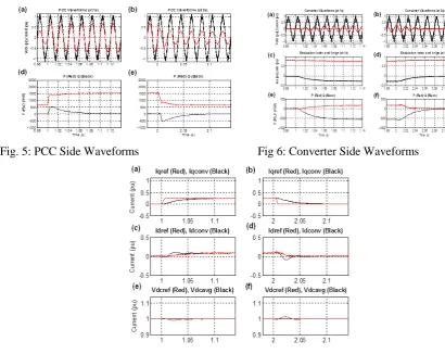
Fig. 9 (a)-(d) shows the PCC side waveforms. Within the time intervals (1 < t < 2) the STATCOM supplies reactive power (capacitive) in eliminate the reactive power absorbed at the PCC. This operation of the STATCOM converter ensures there is no reactive power at the PCC as shown in (c)-(d). The response of the converter takes 0.1s to compensate for reactive power.
Fig. 10 (a)-(f) shows the converter side waveforms. Within the time intervals (1 < t < 2) the STATCOM supplies a capacitive current (+90o) of 2.6 A in (a)-(b). This operation of the STATCOM converter (1 < t < 2) causes a modulation index decrease from 0.81 to 0.78 and increase in the
0 0.5 1 1.5 2 2.5 3 120
140 160
PhaseA DC Top
V o lt s ( V )
0 0.5 1 1.5 2 2.5 3 60
70 80
FCap Top Ca
V o lt s ( V )
0 0.5 1 1.5 2 2.5 3 60
70 80
FCap Top Cb
V o lt s ( V )
0 0.5 1 1.5 2 2.5 3 120
140 160
PhaseA DC Bottom
V o lt s ( V )
0 0.5 1 1.5 2 2.5 3 60
70 80
FCap Bottom Ca
V o lt s ( V )
0 0.5 1 1.5 2 2.5 3 60
70 80
FCap Bottom Cb
[image:8.595.300.505.203.345.2] [image:8.595.310.506.372.522.2]converters angle from -0.02 rads to -0.28 rads as shown in (c)-(d). The reactive power generated from the converter is -560 VAR as shown in (e)-(f).
[image:9.595.71.482.145.471.2]Fig. 11 shows the resulting control signals at the different control blocks and as shown unity power factor correction is achieved between the time intervals (1 < t < 2) .The response time is seen to be 0.1s.
Fig. 5: PCC Side Waveforms Fig 6: Converter Side Waveforms
Fig. 7: Power System Control Signals
Conclusion
This paper has achieved the modelling and analysis of modular multilevel cascade converter based on single-star FC cells (MMCC-SSFC) and discussed how Phase Shifted PWM STATCOM scheme effectively maintains the balancing of the floating capacitors with a modular multilevel flying
capacitor cascade converter based on single-star FC cells (MMCC-SSFC). Simulation results obtained from a 8.28 KVA rated simulation model verify this topology and its operation for voltage regulation and unity power factor correction. This paves the route for experimental validation of the MMFCC in the laboratory.
References
[1] H. P. Mohammadi and M. T. Bina, "A Transformerless Medium-Voltage STATCOM Topology Based
on Extended Modular Multilevel Converters," Power Electronics, IEEE Transactions on, vol. 26, pp. 1534-1545, 2011.
[2] C. Oates, "A methodology for developing Chainlink converters," in Power Electronics and Applications, 2009. EPE '09. 13th European Conference on, 2009, pp. 1-10.
[4] D. Soto and T. C. Green, "A comparison of high-power converter topologies for the implementation of FACTS controllers," Industrial Electronics, IEEE Transactions on, vol. 49, pp. 1072-1080, 2002. [5] H. Akagi, "Classification, Terminology, and Application of the Modular Multilevel Cascade Converter
(MMCC)," Power Electronics, IEEE Transactions on, vol. 26, pp. 3119-3130, 2011.
[6] M. Hagiwara, R. Maeda, and H. Akagi, "Negative-Sequence Reactive-Power Control by a PWM STATCOM Based on a Modular Multilevel Cascade Converter (MMCC-SDBC)," Industry Applications, IEEE Transactions on, vol. 48, pp. 720-729, 2012.
[7] F. Z. Peng, Q. Wei, and C. Dong, "Recent advances in multilevel converter/inverter topologies and applications," in Power Electronics Conference (IPEC), 2010 International, 2010, pp. 492-501. [8] I. B. Efika, C. J. Nwobu, and L. Zhang, "Reactive power compensation by modular multilevel flying
capacitor converter-based STATCOM using PS-PWM," in Power Electronics, Machines and Drives (PEMD 2014), 7th IET International Conference on, 2014, pp. 1-6.
[9] I. B. Efika and L. Zhang, "A Cascaded Flying Capacitor Multilevel Converter for HVDC and FACTs," in Universities High Voltage Network (UHVNet), Winchester 2011.
[10] I. B. Efika, L. Zhang, A. Watson, and J. Clare, "An overlapping multi-hexagon space vector modulation scheme for modular multilevel cascade converters," in Power Electronics and Applications (EPE), 2013 15th European Conference on, 2013, pp. 1-11.
[11] C. J. Nwobu and L. Zhang, "Lifting wavelet transform and energy operator synchronization for a flying capacitor multi-level inverter based active power filter," in Power Electronics and Applications (EPE), 2013 15th European Conference on, 2013, pp. 1-10.
[12] "IEEE Application Guide for IEEE Std 1547(TM), IEEE Standard for Interconnecting Distributed Resources with Electric Power Systems," IEEE Std 1547.2-2008, pp. 1-217, 2009.
[13] "IEEE Standard for Interconnecting Distributed Resources with Electric Power Systems," IEEE Std 1547-2003, pp. 1-28, 2003.
[14] "IEEE Recommended Practices and Requirements for Harmonic Control in Electrical Power Systems," IEEE Std 519-1992, pp. 1-112, 1993.