R E S E A R C H
Open Access
Design and experimental evaluation of a
low-complexity spatial combiner for LTE
distributed antenna systems
Josep Soler-Garrido, Magnus Sandell
*, Filippo Tosato, David Milford and Imran Ahmed
Abstract
This article presents a distributed antenna system (DAS) architecture for small-cell base stations (BTSs), whereby cooperation between the DAS infrastructure and the BTS allows for an increase in performance compared to conventional systems, while at the same time keeping complexity and cost at low levels. Specifically, the article investigates the improvements in uplink physical layer performance achieved by adding an initial antenna combining step in the DAS system before conventional combining and equalization at the BTS. This initial step can be
implemented in a very low-complexity fashion by performing all operations in the time domain and using channel state information calculated at the BTS itself. The article presents this technique in the context of an LTE DAS system. Results from both a software simulator and a custom-made hardware prototype are presented, establishing the feasibility of the proposed architecture.
1 Introduction
In recent times, multiple antenna systems have been one of the main technological drivers for the evolution of wireless communications. In particular, in cellular systems multiple-input multiple-output (MIMO) techniques have successfully been used to increase cell throughput, link capacity, and/or quality [1-3]. Current network deploy-ments typically resort to the use of distributed radio units (RUs) in order to improve the service provided. The so-called remote radio heads containing antennas and RF front-ends but very little processing power [4,5] are strate-gically placed to optimize coverage. These are typically connected to a central unit or base station (BTS) via fibre–optical links, and can significantly increase system capacity and coverage [6]. These distributed antenna sys-tems (DASs) have been proposed as a cheaper alternative to deploying multiple BTSs, for example, in an indoor space to improve coverage [7,8].
In conventional deployments, BTS and DAS are sep-arate subsystems in the overall network. The DAS can be seen as a fixed infrastructure which routes the signal to and from a third party BTS. Its cost is typically related to
*Correspondence: [email protected]
Toshiba Research Europe Ltd., Telecommunications Research Laboratory, 32 Queen Square, Bristol, UK
the area that has to be covered. The BTS itself can have
dif-ferent capabilities which depend on the requirements,e.g.,
total capacity, of the particular deployment. In general, larger deployments in terms of area do not necessarily require a more powerful BTS, especially if the number of users, or their throughput requirements, are low.
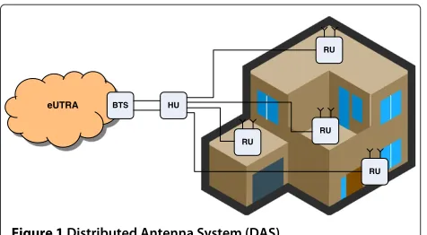
The DAS architecture considered in this article is shown in Figure 1, where a coverage extension network
is deployed within a specific area, e.g., a building. The
system consists of multiple RUs which contain the radio frequency (RF) and antenna elements, and connect to a central hub unit (HU), whose original purpose is to interface between the multiple RUs and the BTS. Given the potentially large number of RUs, this usually requires combining multiple RU signals in the uplink into a num-ber of outputs that is manageable by the BTS, and vice versa for the downlink, where a small number of signals from the BTS are distributed to multiple RUs. Note that the HU may be colocated with the serving BTS, and coop-eration between them can provide certain advantages. This is specially the case in deployments where cost is critical and a large number of RUs have to be served by a small-cell BTS with a small number of antenna ports. The availability of many RUs attached to an HU ensures a
eUTRA BTS HU
RU
RU RU
RU
Figure 1Distributed Antenna System (DAS).
high degree of spatial gain and coverage in the system, but the BTS may be unable to exploit it sufficiently. Conven-tionally, the signals from all RUs are analogue combined in a noncoherent fashion at the HU before conversion [8]. Even if signals to/from different RUs could be handled independently, a typical small BTS subsystem connected to the HU may only support up to two antenna ports. This article presents an adaptive DAS system which makes use of information fed back from the BTS in order to improve performance and coverage. In the proposed sys-tem, the HU itself implements a low-complexity coherent combination of all its input signals. This results in the sub-sequent BTS being only required to handle a small set of inputs. This approach translates into much lower equip-ment costs, especially in larger deployequip-ments requiring a high number of remote units, but where cost or capacity requirements make the use of multiple BTSs with a high number of antenna ports impractical.
Specifically, we present a two-stage coherent combining scheme where the two combiners serve different purposes and jointly exploit the gain offered by a potentially very large number of RUs. Furthermore, in order to keep com-plexity and bill of materials low on the DAS infrastructure side, we explore the possibility to perform the combin-ing stage at the HU only in the spatial domain. Thereafter, the second stage at the BTS performs a conventional frequency selective spatial equalization. Moreover, the combining weight calculation at the HU is assisted by existing channel estimation capabilities at the BTS, reduc-ing complexity further. The HU only performs a simple linear combining operation which does not require the provision of expensive FPGAs or digital signal processors. Our two-stage DAS concept is applied to a 3GPP LTE Release 8 [9] uplink communication setup as an exam-ple. The main deployment scenarios we envisage for our
architecture are those typical for DAS systems,i.e., indoor
office or residential building, and up to small urban cells, where coverage extension is sought without deploying expensive and heavy-maintenance BTS equipments but rather by using inexpensive DAS infrastructure.
The main contributions of this article are
• We provide a description of a DAS for uplink LTE. A (potentially) large number of remote antennas are connected to an HU which processes the signals before passing them on to a BTS. Despite the reduced number of BTS antenna ports, the system is able to exploit the spatial gain provided by the multiple RUs. • As a further simplification, we present the calculation
of space-only combiner weights, such that the amount of synchronization, and domain conversions required at the DAS hardware are kept to a minimum. • A hardware test-bed has been developed in order to
prove the concept. Measurements using a hardware channel emulator allow for a direct comparison between different system architectures, and it is shown that the proposed DAS modifications offer a significant benefit over conventional systems.
The remainder of the article is organized as follows. A system overview of our DAS architecture and motiva-tion for the choice of the two-stage combiner are given in Section 2. The problem of computing the combiner weights is addressed in Section 3 and simulation results are shown in Section 4. The hardware setup and measure-ment results are presented in Section 5, and conclusions are drawn in Section 6.
2 DAS uplink combining
As aforementioned, a key advantage of DAS is that geo-graphically distributed RUs can be connected to a single serving BTS in order to exploit the spatial gain. This can particularly be useful when small cells (and includ-ing femto- or pico-cells) are deployed in indoor spaces to improve coverage and combat interference. The small size and irregular shape of a small cells make the use of RUs very effective in extending/improving coverage with-out generating too much interference on adjacent cells. Besides, significant gains can be exploited to boost the received signal without increasing the transmit power.
Although any number of antennas can be used, a prac-tical problem is that existing small-cell BTSs have much more limited capability compared to macrocell BTSs and may not support more than two antenna ports; hence, the
challenge is to use a potentially large numberNof
anten-nas in a resource-constrained HU where a very limited amount of processing can be done. If cost is to be kept low, implementation of functions such as channel estimation may not be feasible.
calculated is a physical resource block (RB). In this case too, a frequency selective combiner for an OFDM-based system requires substantial processing in the frequency domain which entails a range of relatively complex oper-ations such as discrete Fourier transforms (DFT–IDFT pair), synchronisation, frequency offset compensation, etc. In particular, if the objective of the combiner is that of minimising the mean squared error of the useful sig-nal estimate in the presence of unknown interference, additional estimates of the auto- and cross-correlation are required and a matrix inversion operation is necessary to compute the minimum mean-squared error (MMSE) combiner weights for each active RB. In order to avoid placing such high processing demands on the DAS sys-tem, we propose the use of space-only weights at the HU,
e.g., one set of adaptive weights which applies to all RBs.
Of course, performance of such a simple combiner will be degraded in highly frequency selective channels, espe-cially when using large RB allocations. Simulations and experimental results presented in this article aim to anal-yse this. It should also be noted that in the multiuser case, the radio resource manager (RRM) at the BTS has to be aware of the DAS combining scheme in order to assign entire subframes to users, or group those with similar propagation conditions, so that they share the available bandwidth at any time instant. In the article, we present single-user results intended to quantify the potential per-formance improvements at physical layer attainable by the proposed DAS solution, without going into RRM imple-mentation details.
This solution is effectively a two-stage combiner.
Assuming two antenna ports at the BTS, anN-input
2-outputspatial combinerat the HU, whose aim is to exploit
the spatial gain offered by coherent combining of theN
RUs is followed by a conventional 2-input 1-output MMSE
space-frequency combinerat the BTS, whose main task is to combat noise and unknown interference. This separa-tion of roles between the two combiners is motivated by the choice of a frequency non-selective combiner at the HU. In fact, the limitation of having a single set of weights at the HU for the whole configured bandwidth implies that the HU combiner may have poor noise and interference rejection capabilities if the channel and/or interference are frequency selective across the used spectrum. In this respect, the use of a wideband MMSE solution for the HU combiner is ineffective and may give poor results in most channel conditions as the matrix inversion operation tends to amplify the mismatch between combiner weights and actual auto- and crosscovariances values on each RB. Therefore, our choice for the inner combiner is a simple maximal ratio combiner (MRC).
Of course, in order to calculate weights for the outer HU combiner using channel estimates at the BTS, the latter must have direct (noncombined) visibility of the different
Ninputs at the HU. To allow this, our solution is to
cycli-cally switch between theNantennas at the HU and feed
its signal through to one of the input ports on the BTS.
At the same time, theN antennas are combined and the
combined signal is passed on to the BTS through the other input port. By doing so, the channel can be estimated
periodically for each of the N RU. In the next section,
we motivate our choice of average MRC weights applied across the bandwidth.
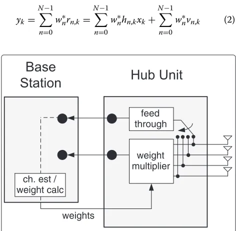
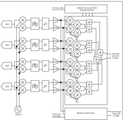
The DAS with the proposed BTS and HU is outlined in Figure 2. The switch at the HU selects one antenna sig-nal and feeds it through to the BTS. Since each individual
antenna is observed at the BTS everyNswitching actions,
if the HU switches every subframe the channel estimates will never be severely outdated for moderate UE speeds. In fact, one of the channel estimates will be right on time, one will be outdated by one subframe, one will be two
sub-frames old and so forth up to theNth oldest estimate that
will experience the largest delay ofNsubframes.
3 Combiner weights
As mentioned in the previous section, at the HU, it is desirable to use the same weights for all subcarriers for reasons of complexity. Since MRC cannot be performed per subcarrier, the weights must be chosen with a global
cost function, i.e., include all subcarriers. The received
signal at the HU withNantennas is
rn,k=hn,kxk+vn,k (1)
wherern,kis the received signal,hn,k is the channel,xk is
the transmitted signal,vn,kis the additive noise andnand
k denote the antenna and subcarrier, respectively. If the
weightsw∗nare used to form the combined output
yk= N−1
n=0
w∗nrn,k= N−1
n=0
w∗nhn,kxk+ N−1
n=0
w∗nvn,k (2)
feed through
weight multiplier
weights ch. est /
weight calc
a reasonable choice of metric would be to maximize the
combined SNRs over theKsubcarriers
K−1
whereγkis the (instantaneous) SNR on thekth subcarrier
andσv2=Evn,k2
is the noise variance. The sum of SNRs in (3) can be written as
This is a Rayleigh quotient [10], so it is clear that
the optimal choice of weights is the eigenvector of R
corresponding to the largest eigenvalue, where Rn,n =
K−1
k=0hn,kh∗n,k. The correlation matrix can also be
com-puted using the impulse response gn,l; if the frequency
response is
whereLis the number of time-domain taps, the
correla-tion matrix is
However, this involves computing the correlation matrix
R(either in the frequency or time domain) and its largest
eigenvector. To reduce complexity further we propose in
this article a simpler way of choosing the weightswn. The
correlation matrix in (6) can be viewed as the sum of that
of allLtaps; if the first tapgn,0is strong compared to the
others, which can be expected for a DAS system, we may
use only that one to estimate the correlation matrixR. In
this case
Rn,n ≈gn,0gn∗,0⇒wn=gn,0. (7)
The first tap of the impulse response can also be computed as
from the IDFT. Hence, the weights can be com-puted as a simple average directly from the frequency
response hn,k without the need for IDFTs or eigenvalue
decomposition.
4 Simulation results
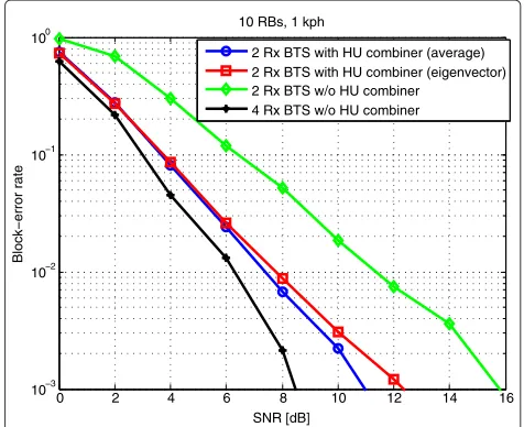
The physical layer of LTE was simulated in Matlab using the Winner II channel models [11]. The worst possi-ble scenario considered in terms of delay spread and frequency selectivity is B1 (urban microcell) with non-line-of-sight (NLOS) propagation; it has 20 channel taps and a delay spread of 485 ns. We use the 10 MHz mode, with up to 50 RBs available, although either 10 RB or 40 RB are considered in the examples provided. The sim-ulations use modulation and coding scheme (MCS) 15, which is 16QAM modulation with a code rate of approx-imately 1/2. The BTS is assumed to have two input ports and the HU is connected to four single-antenna RUs spaced 10 wavelengths apart, a conservative number as DAS systems are expected to benefit from substan-tially uncorrelated antennas. We assume that the average received power per RU is the same; this might be consid-ered a worst-case scenario as well, since more gains can be expected with unequal powers, a more realistic sce-nario. The impact of the approximation (7), introduced in the previous section, is shown in Figure 3 for a single user employing 10 RB, where it can be seen to result in
0 2 4 6 8 10 12 14 16
2 Rx BTS with HU combiner (average) 2 Rx BTS with HU combiner (eigenvector) 2 Rx BTS w/o HU combiner
4 Rx BTS w/o HU combiner
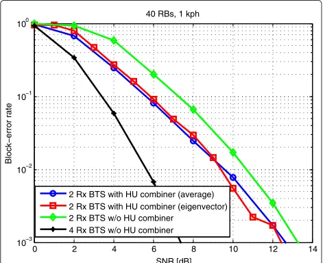
negligible degradation. Its performance is compared to a two- and four-antenna BTS without an HU. The latter is included only as an upper limit to what could be achieved with four antennas since we assume there are only two ports on the BTS. As can be seen, our DAS approach with space-only combining at the HU offers a significant improvement over a system without coherent HU com-bining. As aforementioned, for space-only combining the number of active RBs is important since the channel effec-tively gets wider when they increase. In Figure 4, the block-error rate (BLER) is shown when 40 RBs are used. Although the relative performance is slightly degraded, it offers a clear improvement over a pure two-antenna system.
Finally, and before moving on to the experimental results, we analyse the effect of user equipment (UE) speed on performance. This is interesting as the inher-ent delay on the CSI employed at the HU could render the combiner ineffective in the presence of highly time-varying channels. However, results in Figure 5 show that, at least for the four-antenna case, this is not a criti-cal variable, and the HU combiner offers acceptable performance even for speeds up to 40 km/h, reasonable in a urban microcell scenario.
5 Experimental results
In this section, a hardware prototype of the described uplink LTE DAS system is presented, along with some experiments aimed at quantifying, in practical scenarios and under realistic propagation conditions, the perfor-mance gains that can be attained by the HU processing described in previous section, and linking them with the simulation results provided.
0 2 4 6 8 10 12 14
10−3 10−2 10−1 100
SNR [dB]
Block−error rate
40 RBs, 1 kph
2 Rx BTS with HU combiner (average) 2 Rx BTS with HU combiner (eigenvector) 2 Rx BTS w/o HU combiner
4 Rx BTS w/o HU combiner
Figure 4Performance with a larger number of RBs (40 RBs, 1 km/h).
0 2 4 6 8 10 12 14 16 18
10−3 10−2 10−1 100
SNR [dB]
Block−error rate
10 RBs, 40 kph
2 Rx BTS with HU combiner (average) 2 Rx BTS with HU combiner (eigenvector) 2 Rx BTS w/o HU combiner
4 Rx BTS w/o HU combiner
Figure 5Performance with a larger UE speed (10 RBs, 40 km/h).
5.1 Hardware prototype
The hardware prototype consists of an eNodeB develop-ment system, a test mobile terminal, a custom-made RF board performing the functions of four RUs and an FPGA development board performing HU functions. In order to implement the propagation channel, an Elektrobit C8 hardware emulator is employed. A photograph of the kit is provided in Figure 6.
The eNodeB is a picoChip PC9609 small-cell LTE devel-opment system, with a fully featured Rel. 8 PHY. This system contains two antenna ports and operates in 3GPP
band 13,i.e., with uplink centred at 782 MHz and
down-link at 751 MHz. The bandwidth employed is 10 MHz. In this case, as we are interested in measuring perfor-mance at the physical layer, no protocol stack is employed, using instead a simple PHY driver collecting low level measurements.
Base Station FPGA Unit (combining)
Radio Unit
Fading Emulator
At the other end of the system lies an Aeroflex TM500 test UE, which again is operated in HARQ only mode,
i.e., it establishes only low level communication with the
eNodeB. Most of the settings are manually configured and remain static during the experiments, including uplink and downlink resource allocation, MCS values and trans-mitter power.
An RF board implementing four receivers was built in order to emulate a system with four single-antenna RUs. The basic diagram of this board is depicted in Figure 7. A low-IF architecture is chosen whereby the four independent input (uplink) RF signals are ampli-fied, filtered and downconverted to IF with a centre fre-quency of 15.36 MHz. Thereafter, they are sampled by a transformer coupled ADC for subsequent processing in digital domain. It should be noted that no image-rejection method beyond a simple RF bandpass SAW filter is included on these receivers as they are designed for cabled operation and a single channel at 782 MHz is expected at their input.
The digitized IF signals are processed by two Altera EP1S80 FPGA development boards. These boards actu-ally contain the ADCs from the previous diagram, along with two FPGA devices employed for HU digital signal processing. Since propagation in the prototype is emu-lated in hardware, and hence all the RUs are colocated and next to the HU, the IF signals can directly be con-nected to the ADC inputs. Figure 8 shows a simplified HU processing implementation, where signals are digitally downconverted, with a baseband sampling rate of 15.36 MHz. Two output branches are generated as previously described, with the first one containing a combined sig-nal according to a current set of weights, and the second one being a simple feed-through of one if the inputs, used for training purposes. These two outputs are sent to the inputs of the eNB. It should be noted that in our kit, this
RFIN1 RF
Figure 7Diagram of RF unit for RU implementation.
ADC
Figure 8Diagram of hub unit digital implementation.
is done in the RF domain, so subsequent DAC and upcon-version stages are required, which are not shown in the diagram. The RF signals from this point onwards are nor-malized at a constant sufficiently high level for the eNB RF front end.
The weight calculation modules updates the weights every millisecond, but CSI for only one of the four branches is updated on every subframe period. In the pro-totype, this CSI for the antenna port used for training is sampled at the HU from the digital GPIO outputs at the eNodeB baseband chip. The communication is performed in serial mode, with a single coefficient being sent for each RB in 32-bit format (I and Q), followed by a single scaler applied at the BTS across the entire bandwidth.
5.2 Measurements
are entirely due to random fading, which in this case is uncorrelated for all the antennas.
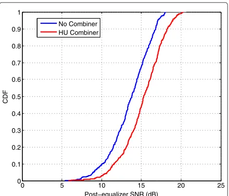
The first empirical distribution measured, for the case of 10 RB and 1 km/h user speed is shown in Figure 9. A clear performance improvement is observed for the HU-combiner case, increasing the measured average SNR from 14.2 dB in the two-antenna case to approximately
16.2 dB,i.e., a postequalization gain of 2 dB. Looking at
the left-hand tail of the distributions, a substantial reduc-tion in outage probability can also be intuitively expected. These results can also be linked to the previous simu-lated ones. The measurements correspond to SNR at the input of the channel decoder, so given the simulated per-formance curves for the LTE turbo code at different rates, it is possible to map each measured SNR sample to an expected error rate, and then compute an average. For
the presented distribution, an error rate of 3.2×10⁻²is
obtained for the no HU-combiner case, which is improved
to approximately 4.5×10⁻³for the combined case.
Look-ing at Figure 3, the measurements are consistent with simulated ones at an input SNR level of between 9 and 10 dB.
The second set of results measure the reduction in gain when moving to 40 RBs. Figure 10 shows the empirical distribution. In this case, the gap between the two empir-ical distributions is reduced, but gains are still noticeable. The HU combiner is now able to increase average SNR from 14.2 dB to 15.8 dB. In terms of expected BLER, the
distributions shown yield approximately 1.5×10⁻² for
the no combiner case and 6.0×10⁻³ for the HU
com-biner, which are again consistent with simulated results on Figure 4 at a similar SNR range, in fact indicating a slightly lower than expected BLER in the measured results when
0 5 10 15 20 25
0 0.1 0.2 0.3 0.4 0.5 0.6 0.7 0.8 0.9 1
Post−equalizer SNR (dB)
CDF
No Combiner HU Combiner
Figure 9Measured distributions for 10 RB and 1 km/h UE speed.
0 5 10 15 20 25
0 0.1 0.2 0.3 0.4 0.5 0.6 0.7 0.8 0.9 1
Post−equalizer SNR (dB)
CDF
No Combiner HU Combiner
Figure 10Measured distributions for 40 RB and 1 km/h UE speed.
the HU combiner is enabled. Such small variations could
be attributed to,e.g., differences between the simulated
channel model and the fixed-point one implemented on the C8, which only approximates the delays of the taps in order to reduce hardware resources.
Finally, measured results for different speeds are pro-vided in order to show the robustness of the method to high mobility scenarios. Figure 11 shows measured aver-age SNR and expected block error rates for the previous 10 RB case at 1, 5, 20 and 40 km/h. As can be observed, the slight CSI latency in the HU combiner has no signif-icant impact on performance at moderate speeds typical of the chosen scenario, confirming previous simulation results.
0 5 10 15 20
Average SNR
1 5 20 40 10
−3
10−2 10−1 100
UE speed (km/h)
Expected BLER
BLER No combiner BLER HU combiner SNR No combiner SNR HU combiner
6 Conclusions
In this article, we propose a DAS architecture suitable for small-cell BTSs. It provides a low-complexity solution able to make better use of the spatial gain in the uplink of DAS while still employing low-cost BTS hardware. This is achieved by introducing an initial combining stage at the HU, where signals from different RUs are coher-ently combined. The article explores the performance of a space-only combiner where the uplink SNR is enhanced by applying a single set of weights across all frequencies at the HU. These results are backed by measurements from a hardware prototype making use of a precommercial Rel. 8 eNodeB, a custom-made RF and digital baseband combiner setup, a test LTE UE and a hardware channel emulator. The experimental results show clear perfor-mance gains for the combiner case even when the average received power is the same for all RUs. Moreover, the mea-surements are in line with simulated results, establishing the feasibility of the proposed architecture in practical real-life deployment in the presence of practical hardware impairments and realistic propagation conditions.
Competing interests
The authors declare that they have no competing interests.
Acknowledgements
The authors would like to thank the directors at Toshiba’s Telecommunication Research Laboratory in Bristol for their constant support. They would also like to acknowledge the support of the Wireless Systems Laboratory at Toshiba’s Corporate R&D Center, and especially the assistance provided by Dr. Tsuguhide Aoki throughout the entire project. They would also like to acknowledge the work done by Yue Tian during his MSc internship at Toshiba TRL supporting this project.
Received: 29 September 2012 Accepted: 18 February 2013 Published: 14 March 2013
References
1. Q Li, G Li, W Lee, M Lee, D Mazzarese, B Clerckx, Z Li, MIMO techniques in WiMAX and LTE: a feature overview. IEEE Commun. Mag.48(5), 86–92 (2010)
2. J Andrews, W Choi, R Heath, Overcoming interference in spatial multiplexing MIMO cellular networks. IEEE Wirel. Commun. Mag.14(6), 95–104 (2007)
3. QH Spencer, AL Swindlehurst, M Haardt, Zero-forcing methods for downlink spatial multiplexing in multiuser MIMO channels. IEEE Trans. Signal Process.52(2), 461–471 (2004)
4. SG Park, BH Ryu, DY Kim, inProceedings of IEEE International Conference on ICT Convergence (ICTC). Uplink multi-point reception effect using aggregate base station architecture (Seoul, Korea, 2011), pp. 172–176 5. S Pato, J Pedro, J Santos, A Ars´enio, P In´acio, P Monteiro, inProceedings of
the Instituto de Telecomunicac¸˜oes Conference on Telecommunication (ConfTele). On building a distributed antenna system with joint signal processing for next-generation wireless access networks: the FUTON approach (Santa Maria de Feira, Portugal, 2009)
6. H Li, J Hajipour, A Attar, V Leung, Efficient HetNet implementation using broadband wireless access with fiber-connected massively distributed antennas architecture. IEEE Wirel. Commun.18(3), 72–78 (2011) 7. MJ Crisp, S Li, A Watts, RV Penty, IH White, Uplink and downlink coverage
improvements of 802.11g signals using a distributed antenna network. J. Lightw. Technol.25(11), 3388–3395 (2007)
8. D Wake, A Nkansah, NJ Gomes, Radio over fiber link design for next generation wireless systems. J. Lightw. Technol.28(16), 2456–2464 (2010)
9. 3GPP TR 36211 v890, E-UTRA physical channels and modulation (2009). [http://www.3gpp.org/ftp/Specs/archive/36 series/36.211/36211-890. zip]
10. G Strang,Linear Algebra and Its Applications, 3rd edn. (Harcourt Brace Jovanovich, San Diego, USA, 1986)
11. P Ky ¨osti, J Meinil¨a, L Hentil¨a, X Zhao, T J¨ams¨a, C Schneider, M Narandzic, M Milojevic, A Hong, J Ylitalo, VM Holappa, M Alatossava, R Bultitude, Y de Jong, T Rautiainen, WINNER II channel models (2007). [http://www.ist-winner.org/WINNER2-Deliverables/D1.1.2v1.1.pdf]
doi:10.1186/1687-1499-2013-69
Cite this article as:Soler-Garridoet al.:Design and experimental evaluation
of a low-complexity spatial combiner for LTE distributed antenna systems. EURASIP Journal on Wireless Communications and Networking20132013:69.
Submit your manuscript to a
journal and benefi t from:
7Convenient online submission 7 Rigorous peer review
7Immediate publication on acceptance 7 Open access: articles freely available online 7High visibility within the fi eld
7 Retaining the copyright to your article