UNIVERSITI TEKNIKAL MALAYSIA MELAKA
Analysis of Surface Integrity of Honeycombed
Aero Composite Material in Drilling with HSS
Cutting Tool
Thesis submitted in accordance with the requirements of the Universiti Teknikal Malaysia Melaka for the Bachelor Degree of Manufacturing
Engineering in Manufacturing Process
By
Mohd Azrul Hisham Bin Abdul Kadir
(B050310094)
ANALYSIS OF SURFACE INTEGRITY OF
HONEYCOMBED AERO COMPOSITE MATERIAL IN
DRILLING WITH HSS CUTTING TOOL
MOHD AZRUL HISHAM BIN ABDUL KADIR
SULIT
TERHAD
√ TIDAK TERHAD
(Mengandungi maklumat yang berdarjah keselamatan atau kepentingan Malaysia yang termaktub di dalam AKTA RAHSIA RASMI 1972)
(Mengandungi maklumat TERHAD yang telah ditentukan oleh organisasi/badan di mana penyelidikan dijalankan)
(TANDATANGAN PENULIS)
Alamat Tetap:
694 KAMPUNG PADANG MACHANG, MANIR, 21200
KUALA TERENGGANU
Tarikh: 09/05/2007
Disahkan oleh:
(TANDATANGAN PENYELIA)
Cop Rasmi:
Tarikh: _______________________
* Tesis dimaksudkan sebagai tesis bagi Ijazah Doktor Falsafah dan Sarjana secara penyelidikan, atau disertai bagi pengajian secara kerja kursus dan penyelidikan, atau Laporan Projek Sarjana Muda (PSM). ** Jika tesis ini SULIT atau TERHAD, sila lampirkan surat daripada pihak berkuasa/organisasi berkenaan dengan menyatakan sekali sebab dan tempoh tesis ini perlu dikelaskan sebagai SULIT atau TERHAD.
BORANG PENGESAHAN STATUS TESIS*
UNIVERSITI TEKNIKAL MALAYSIA MELAKA
JUDUL: ANALYSIS OF SURFACE INTEGRITY OF HONEYCOMBED AERO COMPOSITE MATERIAL IN DRILLING WITH HSS CUTTING TOOL
SESI PENGAJIAN: 2006/2007
Saya _______________MOHD AZRUL HISHAM BIN ABDUL KADIR_____________
mengaku membenarkan tesis (PSM/Sarjana/Doktor Falsafah) ini disimpan di Perpustakaan Universiti Teknikal Malaysia Melaka (UTeM) dengan syarat-syarat kegunaan seperti berikut:
1. Tesis adalah hak milik Universiti Teknikal Malaysia Melaka.
2. Perpustakaan Universiti Teknikal Malaysia Melaka dibenarkan membuat salinan untuk tujuan pengajian sahaja.
3. Perpustakaan dibenarkan membuat salinan tesis ini sebagai bahan pertukaran antara institusi pengajian tinggi.
4. **Sila tandakan (√)
APPROVAL
This thesis submitted to the senate of UTeM and has been accepted as partial
fulfillment of the requirements for the degree of Bachelor of Manufacturing
Engineering (Manufacturing Process)
The members of the supervisory committee are as follow:
……….
Main Supervisor
(Mr. Raja Izamshah Bin Raja Abdullah )
13 April 2007
……….
Co-Supervisor
(En. Mohd. Hadzley bin Abu Bakar)
ii
DECLARATION
I hereby, declare this thesis entitled “Analysis of Surface Integrity of Honeycombed
Aero Composite Material in Drilling with HSS Cutting Tool” is the result of my own
research except as cited in the references.
Signature : ………
Author’s Name : Mohd Azrul Hisham Bin Abdul Kadir
DEDICATION
”Especially dedicated to my parents, family and friends that helps me in completing
iv
ACKNOWLEDGEMENT
Alhamdulillah. Thanks to Allah S.W.T because of the blessing I can complete this
thesis. I would like to thanks to my supervisor Raja Izamshah Bin Raja Abdullah for
guiding me in completing this thesis. Also a lot of thanks to the technician of
material laboratory and the NDT lab in FKP for helping me in finishing the research
ABSTRACT
This thesis investigates the effect of the drilling parameters, (cutting speed and cutter
diameter) in drilling of aero composite material with different fiber fractions. Three
speeds (low, medium and high) and five cutter diameter with different size are used
in this study. The results show that the cutting speed and cutter diameter have direct
effects on crack and surface roughness on the work piece. On the other hand,
increasing the cutting speed reduces the associated crack and surface roughness,
especially for large cutter diameter. The influence of cutting parameters on peel-up
and push-out delaminations that occurs at drill entrance and drill exit respectively at
the specimen surfaces have been investigated. No clear effect of the cutting speed on
the delamination size is observed, while the delamination size decreases with
vi
ABSTRAK
Tesis ini menyiasat tentang kesan parameter penggerudian, (kelajuan dan diameter
pemotong) penggerudian pada bahan komposit dengan pecahan-pecahan gentian
berbeza. Tiga kelajuan digunakan iaitu (rendah , sederhana dan tinggi) dan lima jenis
diameter pemotong digunakan dengan saiz yang berbeza Keputusan menunjukkan
bahawa kelajuan pemotongan dan diameter pemotong adalah berkadar terus ke atas
kesan keretakan dan kekasaran permukaan pada bahan kerja. Sebaliknya,
peningkatan kelajuan proses pememotongan mengurangkan kesan keretakan dan
kekasaran pada permukaan bahan kerja, terutamanya pada diameter pemotong yang
bersaiz besar.Parameter yang mempengaruhi pemotongan pada permukaaan kulit
atas dan menghentikan delaminations yang berlaku di bahagian luar penggerudian
dan menggerudi bahagian keluar pada spesimen permukaan-permukaan telah
LIST OF CONTENT
APPROVAL ... i
DECLARATION ... ii
DEDICATION ... iii
ACKNOWLEDGEMENT ... iv
ABSTRACT ... v
ABSTRAK ... vi
LIST OF CONTENT ... vii
LIST OF FIGURE ... ix
LIST OF TABLE ... xii
CHAPTER 1 ... 1
INTRODUCTION ... 1
1.1 Background of Project ... 1
1.2 Problem Statement ... 2
1.3 Objective Project ... 3
1.4 Scope of Project ... 3
CHAPTER 2 ... 4
LITERATURE REVIEW ... 4
2.1 Composite Material ... 5
2.1.1 Composite background ... 5
2.1.2 Composite Structure ... 7
2.2 Principle of Machining Process ... 9
2.2.1 Drilling Process ... 9
2.2.2 Drilling Cutter ... 10
2.2.3 Machining parameter ... 13
2.3 Tool Wear ... 15
2.3.1 Tool wear phenomena ... 16
viii
2.3.4 Tool Failed Due to Excessive Wear ... 22
2.3.5 Tool Nose Radius Effect On Cast Iron Milling PCBN Tooling ... 23
2.4 Coating ... 24
2.6 Scanning Electron Microscope (SEM) ... 33
CHAPTER 3 ... 35
METHODOLOGY ... 35
3.1 Selection of machine ... 35
3.1.1 CNC machine ... 35
3.1.2 Scanning electron microscope ... 38
3.2 Selection of the work material ... 41
3.3 Selection of cutting tool ... 42
3.4 Selection of cutting parameters ... 43
3.5 Experiment procedure ... 44
3.6 Flow chart of experimental procedures ... 51
CHAPTER 4 ... 52
RESULT AND DISCUSSION ... 52
CHAPTER 5 ... 74
CONCLUSIONS AND RECOMMENDATIONS ... 74
LIST OF FIGURE
Figure 1: Sandwich construction. [1] ... 7
Figure 2: Schematic illustration of the basic principle of the drilling operation with important features/dimensions [2] ... 10
Figure 3: Common Types of Drills Bits [2] ... 11
Figure 4: Typical Drilling Processes [2] ... 11
Figure 5: illustrate of term applying to Twist Drills ... 12
Figure 6: Illustration of speed, feed and depth of cut ... 14
Figure 7: Tool wear phenomena ... 17
Figure 8: The above figure shows the image of the -45º rake tool before the cutting tests. [8] ... 17
Figure 9: (a) Cutting edge of the tool after a total depth of cut of 25 µm (No appreciable tool wear can be seen. The cutting edge is degraded a little bit. (b) Cutting edge of the tool after a total depth of cut of 100 µm (The edge just starts to wear on the flank face. Flank wear is noticeable) [8] ... 18
Figure 10: (a) Cutting edge of the tool after a total depth of cut of 175 µm (Rib like features which are similar to abrasive wear on the flank face could be clearly seen). ... 19
Figure 11: Inserts Work material = 4140 Steel, TiN Coated Carbide Tool Inserts Tool-life (ISO standard: 0.8 mm localized flank wear) = 5 min. 54 sec. (V = 400 m/min, f = 2 m/min and a = 4 mm) [9] ... 20
Figure 12: Work material = 4140 Steel, TiN Coated Carbide Tool Inserts Tool-life (ISO standard: 0.8 mm localized flank wear) = 9 min. 8 sec. (V = 400 m/min, f = 1 m/min and a = 7 mm) [9] ... 20
Figure 13: PCBN tool illustrating mechanical impact failure of the cutting edge. ... 21
x
Figure 17: Surface characteristics ... 28
Figure 18: Surface texture includes roughness and waviness. Many surfaces have lay: directional striations across the surface. ... 30
Figure 19: A profile is a two-dimensional picture of a three dimensional surface that may be thought of as the result of a sectioning place cutting the surface. Profiles are ordinarily taken perpendicular to the lay. ... 32
Figure 20: Illustrations of SEM machine ... 34
Figure 21: CNC Milling Machine ... 36
Figure 22: Shear Cutting Machine ... 37
Figure 23: Composite specimen ... 37
Figure 24: Scanning electron microscope machine (SEM) ... 38
Figure 25: Nomenclature of SEM [23] ... 38
Figure 26: Measurement process ... 39
Figure 27: Print out of the surface roughness value ... 40
Figure 28: Composite Material ... 41
Figure 29: Cutting tool ... 42
Figure 30: Raw Material from scrap CTRM ... 44
Figure 31: Shear Cutting Machine ... 44
Figure 32: Drill the holes ... 45
Figure 33: Tight the drill bit in the drilling machine ... 46
Figure 34: Remove the drill bit from the drilling machine ... 46
Figure 35: Clean the machine ... 46
Figure 36: Scanning Electron Microscope (SEM) ... 47
Figure 37: Cut the specimen to check the surface roughness ... 47
Figure 38: Specimen after cut using hand saw ... 48
Figure 39: Portable Surface Roughness Tester ... 48
Figure 40: Taking measurement ... 49
Figure 41: Print out the result ... 49
Figure 42: Experiment flowchart ... 50
Figure 43: Ø 4.0 mm ... 53
Figure 44: Ø 4.5 mm ... 53
Figure 46: Ø 5.5 mm ... 54
Figure 47: Ø 6.0 mm ... 55
Figure 48: Ø 4.0 mm ... 56
Figure 49: Ø 4.5 mm ... 57
Figure 50: Ø 5.0 mm ... 57
Figure 51: Ø 5.5 mm ... 58
Figure 52: Ø 6.0 mm ... 58
Figure 53: Ø 4.0 mm ... 59
Figure 54: Ø 4.5 mm ... 60
Figure 55: Ø 5.0 mm ... 60
Figure 56: Ø 5.5 mm ... 61
Figure 57: Ø 6.0 mm ... 61
Figure 58: Crack at cutting speed 75 rpm at Ø 4 mm (Peel-up) ... 63
Figure 59: Crack at cutting speed 75 rpm at Ø 4 5mm (Peel-up) ... 64
Figure 60: Crack at cutting speed 75 rpm at Ø 6 mm (Peel-up) ... 65
Figure 61: Crack at cutting speed 325 rpm at Ø 4 mm (Push-out) ... 66
Figure 62: Crack at cutting speed 1050 rpm at Ø 4 mm (push-out) ... 67
[image:14.595.95.513.82.482.2]Figure 63: Morphology of drilling holes processes ... 68
Figure 64: Graph of surface roughness vs. ø drill cutter for sampling length 0.25mm ... 71
Figure 65: Graph of surface roughness vs. ø drill cutter for sampling length 0.08mm ... 71
xii
LIST OF TABLE
Table 1: Sampling length for appendices profile roughness parameter (Ra, Rq, Rsk,
Rku, RΔq) material ratio curve, probability density function and related parameter. 29
Table 2: Specifications of CNC Milling Machine ... 36
Table 3: Surface roughness obtain using different diameter cutter and cutting speed
for High Speed Steel Drill Bit (HSS) for sampling length 0.25mm ... 69
Table 4: Surface roughness obtain using different diameter cutter and cutting speed
CHAPTER 1
INTRODUCTION
1.1 Background of Project
Because composite material have superior properties such as high
strength-to-weight ratio, high stiffness-to-strength-to-weight ratio, excellent fatigue resistance and low thermal
expansion coefficient, they are generally used to fabricate a variety of component for
automotive, aerospace, marine, and consumer product. Various cutting techniques are
available to drill holes, but drilling is the common way in secondary machining of
composite material owing to the need for structure joining. The mechanics of drilling
composite material has been studies along with the quality of the hole and the effects of
tool geometry and toll material.
Several hole production processes, including conventional drilling, ultrasonic
drilling, laser-beam drilling, water jet drilling, etc., have been proposed for a variety of
economic and quality reasons. Conventional drilling is still the most widely used
technique in industry today. A major concern that has received considerable attention in
drilling holes in FRCM is the delamination, especially at the bottom surface of the
workpiece (drill exit). The thrust force developed during the drilling process affects the
2 1.2 Problem Statement
The use of fiber-reinforced composite materials in automobile and aerospace
industries has grown considerably in recent years because of their unique properties such
as high specific stiffness and strength, high damping, good corrosive resistance, and low
thermal expansion. Drilling is usually the final operation during the assembly of the
structures in these applications. Any defects that lead to the rejection of the parts
represent an expensive loss. For example, in the aircraft industry, drilling-associated
delamination accounts for 60% of all part rejections during final assembly of an aircraft.
The economic impact of this is significant considering the value associated with the part
when it reaches the assembly stage. The quality of the drilled holes such as
waviness/roughness of its wall surface, axial straightness, and roundness of the hole
cross-section can cause high stresses on the rivet, which will lead to its failure. Stress
concentration, delamination, and micro cracking associated with machined holes
significantly reduce the composites performance. Thus this thesis will investigate the
effect of cutting speed and cutter diameter in drilling of aero composite with
honeycombed structure in order to reduce part rejection during final assembly of an
aircraft.
1.3 Objective Project
1) To understand the science and technology of surface integrity in machining
process.
2) To determine the defect occur on the composite surface with difference drilling
parameter (cutting speed and cutter diameter).
3) To measure the surface roughness of the drilled hole with different drilling
parameter (cutting speed and cutter diameter).
1.4 Scope of Project
1) Drilling the aero composite with different drilling parameter (cutting speed and
cutter diameter) using HSS cutting tool.
2) Measure the surface roughness of the drilled hole using profilometer.
4
CHAPTER 2
LITERATURE REVIEW
The literature review is conducted to achieve the objectives for this research. The
literature is included information on coated carbide tools used in milling, coating
materials for cutting tools, wear observation during turning operations and surface finish
of the machined work material. All of this information is served as guideline in the
course of the study. These research studies are involved in using the:
1) Composite Material
2) Drilling machine
3) Scanning Electron Microscope
2.1 CompositeMaterial
A composite material is a combination of a strong material (usually as a fiber)
embedded in a weaker matrix. The combination produces a new material with properties
that can greatly outperform the properties of either component [1].
2.1.1 Composite background
The principals of composite materials can be found all around us. Reinforced
concrete is one example of a material in which various elements combine to create a
stronger, tougher material than the sum of its individual components. Typically the term
‘advanced composites’ refers to carbon, Kevlar or other highly engineered fibers
embedded in an epoxy matrix. The epoxy matrix in composites serves to distribute stress
loads evenly between the embedded fibers. The epoxy also stiffens the composite when
cured into the desired form. [1].
The properties of certain fibers make them extremely strong in tension. Glass
fibers, carbon fibers and Kevlar have very high tensile strength. Though strong and light
weight these fibers lack stiffness on their own. Also, imperfections on the surface of the
fibers can cause stress points, which will open to fractures under strain. When fibers are
woven together the multiple fibers act to divide strain so that it is not concentrated in
any one fiber.
The combination of composite strength and low weight has been applied where
high material performance is paramount. Initial applications of advanced composite
technology were for military and space programs, where high strength to weight ratios
were a necessity and cost was not critical. Since then, advanced composites have found
their way into a variety of everyday uses.
The Kevlar in bulletproof vests is incredibly tough. High performance sporting
6
Fiberglass watercrafts are a mature technology that has dramatically changed the boat
building industry. As composites have become better understood they have become
preferred materials for aircraft.
There are five key factors that determine the weight and cost of composite structures:
1) Labor content
2) Cost of machinery
3) Cost of materials
4) Tooling and assembly requirements
5) Curing requirements
Early composite fabrication techniques used dry-fiber broad goods laid up by
hand with resins applied by hand. Most current composites manufacturing relies on fiber
broad goods that are pre impregnated with resin. These pre impregnated are still
laboriously laid up by hand. These techniques use expensive materials and are very labor
intensive, limiting their practical commercial application.
Composite parts made using the current state-of-the-art methods typically
include core stiffeners, including various kinds of specialized foams or honeycombs.
These materials represent a significant cost in materials and labor for their application in
addition to increasing weight and reducing usable volume. Spectrum’s processes
drastically reduce the need for core stiffeners. [2]
Curing high performance composite parts generally requires applying both
external heat and pressure to the part. This is typically accomplished using expensive
autoclaves.
With traditional composite fabrication techniques it can also be difficult to control the
manufacturing process with verifiable precision. This and other ‘knock-down’ factors
force manufacturers to add weight and cost to load bearing parts in order to meet FAA
certification requirements. This has tended to make testing, process controls and
2.1.2 Composite Structure
Composites are materials consisting of a com- bination of high-strength stiff
fibers embedded in a common matrix (binder) material; for example, graphite fibers
and epoxy resin. Composite structures are made of a number of fibers and epoxy resin
laminates. These laminates can number from 2 to greater than 50, and are generally
bonded to a substructure such as aluminum or nonmetallic honeycomb. The much
stiffer fibers of graphite, boron, and Kevlar® epoxies have given composite materials
structural properties superior to the metal alloys they have replaced.
The use of composites is not new. Fiber glass, for example, has been used for
some time in various aircraft components. However, the term advanced composites
applies to graphite, boron, and Kevlar®, which have fibers of superior strength and
stiffness. The use of these advanced composite materials does represent a new
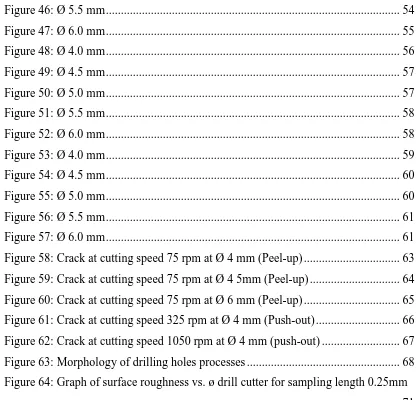
[image:22.612.186.439.391.608.2]application for naval aircraft. [1]
Figure 1: Sandwich construction. [1]
Composite materials are replacing and supple- menting metallic materials in
8
replacement of metallic materials with more advanced composite materials has rapidly
accelerated. This has become particularly evident with the advent of the F/A-18,
AV-8B, SH-60B, and CH 53E aircraft; and it is anticipated that composite materials will
continue to comprise much of the structure in future aircraft. As a result, there is a
growing requirement to train you in the use of advanced composite materials.
There are numerous combinations of composite materials being studied in
laboratories and a number of types currently used in the production of aircraft
components. Examples of composite materials are as follows: graphite/epoxy,
Kevlar®/epoxy, boron poly- amide, graphite polyamide, boron-coated boron
aluminum, coated boron titanium, boron graphite epoxy hybrid, and boron/epoxy. The
trend is toward minimum use of boron/epoxy because of the cost when compared to
current generation of graphite/epoxy composites.
Composites are attractive structural materials because they provide a high
strength/weight ratio and offer design flexibility. In contrast to traditional materials of
construction, the properties of these materials can be adjusted to more efficiently
match the requirements of specific applications. However, these materials are
highly susceptible to impact damage, and the extent of the damage is difficult to
determine visually. Nondestructive inspection (NDI) is required to analyze the
extent of damage and the effectiveness of repairs. In addition, repair differs from
2.2 Principle of Machining Process
Machining is essentially the process of removing unwanted material from
wrought (roller) stock, forgings, or casting to produce a desire shape, surface finish and
dimension. It is one of the four major types of manufacturing processes used to create
product component. Machining is done by shaving away material in small pieces, called
chips using very hard cutting tools powerful, rigid machine tools. The cutting tools may
be held stationary and moved across the rotating workpiece as on a lathe or a rigid held
work piece may move into a rotating cutting tool as a milling machine.
Historically, machining process probably began with Besson in 1569 when he
invented the screw-cutting lathe and later when a practical version was built by Henry
Maudslay in 1800. Horizontal milling machine first appeared in 1820 when Eli Whitney
used them for the manufacture of firearm, and the vertical milling first appeared in 1860.
Machining processes remove material in the form of chips that are disposed or recycled.
Machining is more costly than casting, molding, and forming processes, which are
generally quicker and waste less material, but machining is often justified when
precision is needed. [3]
2.2.1 Drilling Process
The drilling machine (drill press) is a single purpose machine for the production
of holes. Drilling is generally the best method of producing holes. The drill is a
cylindrical bar with helical flutes and radial cutting edges at one end. The drilling
operations simply consist of rotating the drill and feeding it into the work piece being
drilled. The process is simple and reasonably accurate and the drill is easily controlled
both in cutting speed and feed rate. The drill is probably one of the original machining
![Figure 1: Sandwich construction. [1]](https://thumb-us.123doks.com/thumbv2/123dok_us/141023.18167/22.612.186.439.391.608/figure-sandwich-construction.webp)
