BEHAVIOUR OF RECTANGULAR RC COLUMNS
RETROFITTED BY FIBRE REINFORCED
POLYMERS UNDER AXIAL AND CYCLIC LOADING
H Shaheen T Elrakib
Housing and Building Research Centre
I Shaaban A Abdelrahman
Zagazig University Ain Shams University Egypt
ABSTRACT. Retrofitting of reinforced concrete elements with fibre reinforced polymers, (FRP), wraps is one of the repair techniques used successfully for the last few years. Previous investigations have been concerned with the behaviour of rectangular RC columns strengthened by FRP wraps under axial loading. Consequently, a comprehensive study of the different parameters affecting the seismic behaviour of RC columns is important. The objectives of the research described in this paper are to carry out an experimental investigation to study the behaviour of rectangular RC columns wraped with FRP sheets under cyclic lateral and axial loading. The main parameters investigated in the research are: different anchorage systems, volumetric ratio of FRP and spacing between FRP layers. Five columns with dimensions 150x 450x2300 mm were tested under both cyclic lateral and axial loading. Different recommendations are provided for the use of FRP in strengthening rectangular columns.
Keywords: CFRP, Columns, Cyclic loading, Seismic, Anchorage
H Shaheen is a Professor and Head of Department of RC, HBRC, Giza, Egypt. His research interests include the structural behavior of RC, seismic analysis of such structures , advanced composite materials (ACM) and nonlinear static and dynamic analysis of RC structures. I Shaaban is an Associate Professor for the analysis and design of RC structures in Civil Engineering Deptartment at Zagazig Univ.,Cairo,Egypt. He obtained his MSc from Ain Shams University, Cairo, Egypt, in 1988 and his PhD from University of Dundee, Scotland, in 1993. His research interests include the structural behavior of RC, seismic analysis of such structures and repair of RC structures.
A Abdelrahman is an Associate Professor for the analysis and design of RC structures in Civil Engineering Department at Ain Shams University, Cairo, Egypt. He is an associate member of ACI 440 code committee and his research interests include the structural behavior of RC, retrofitting of RC structures and the use of ACM.
INTRODUCTION
Recently, attention has been focused on the use of fibre reinforced polymers FRP composite materials for structural rehabilitation. If correctly used, FRP composites can result in significant enhancement to both ductility and strength of RC members. Also, FRP can generally be applied while the structure is in use and with negligible changes in the member dimensions. Several studies on various aspects related to the subject have been published recently. The confinement of RC columns with FRP tubes, sheets and straps is among those research topics considered. Most of the previous work was undertaken on small columns, circular columns or columns subjected to axial loading only [1, 2, 5]. Rectangular columns, with aspect ratio 1 up to 5, are commonly used for residential buildings. Consequently, a comprehensive study of the seismic behaviour of rectangular RC columns retrofitted by FRP is important.
This paper investigates the performance of rectangular RC columns wrapped by FRP sheets and subjected to a combined axial compression and cyclic flexural loading. Rectangular RC columns of aspect ratio 1 to 3 were tested under constant axial load and increasing cyclic lateral load up to failure. Carbon FRP, (CFRP) wraps were used with different volumetric ratio, spacing and with or without anchors. The displacement ductility, strength, stiffness and energy dissipation capacity were evaluated and compared for different techniques of retrofitting.
TEST PROGRAM
The test program includes five specimens with rectangular cross section designated as Cl to C5. The columns were tested horizontally under constant axial load combined with cyclic lateral load. The columns have a total height of 2300 mm and a cross section of 150x450 mm. It consisted of the right part of 1300 mm long and the left part with a length of 700 mm and a beam stub in the middle as shown in Fig.l. The right part of each specimen constituted the test portion. It represents a column extending from the beam-column connection to the point of infliction. The beam stub, which was heavily reinforced, provided a point of application for the lateral load.The dimensions of the beam stub were chosen so that the failure would occur in the column rather than at the joint. The left portion was also heavily reinforced and provided with two 6mm thick steel plates, which were anchored to the specimen by steel bolts of 16 mm diameter, in order to force hinging into the right part and thereby reducing the amount of instrumentation needed. The longitudinal reinforcement ratio of the columns, in the right part, was 1% and the bars were uniformly distributed around the core perimeter. Stirrups in the same right part were 6mm diameter bars every 150 mm with a volumetric ratio of 0.3%. For the left part, stirrups were 8mm diameter bars every 100 mm. CFRP laminates were applied to strengthen the columns C2 through C5 with different schemes.The thickness of CFRP laminates was 0.11 mm, while its tensile strength and modulus of elasticity were 2400 MPa and 240 GPa, respectively. The characteristic compressive cube strength of the concrete after 28 days was 25 MPa while the yield stress of the steel was 420 MPa for the long reinforcement and 310 MPa for stirrups.
Test Specimens
2.
Behaviour of Retrofitted CFRP Columns 341
Specimen Cl is the reference specimen. A constant axial compression load of 0.15fcuAc
was applied on the specimen up to failure. This axial compression load was kept constant for all specimens.
Specimen C2 was wrapped in the transverse direction with two layers of lateral CFRP laminates of 100 mm width .The clear distance between laminates was 100 mm and the volumetric ratio of FRP was 0.2%.
3. Specimen C3 was wrapped with one CFRP layer with a FRP volumetric ratio of 0.1%. 4. Specimen C4 was wrapped with one layer of CFRP with no spacing between the layers.
The volumetric ratio of FRP was 0.2%.
[image:3.612.64.414.259.577.2]5. Specimen C5 was wrapped with one layer of CFRP as for specimen C3. Steel plates of 50mm width, 190mm length, 12mm thickness and 240 MPa yield stress, were used to anchor the lateral laminates. The plates were discontinuous, this is to investigate the steel plates contribution to concrete confinement and increasing the ductility of columns, independently from their contribution to the flexural capacity of columns
Table 1 Details of the tested specimens
No.
COLUMN
DIMENSIONS (mm)
NO. SPACING WIDTH ANCHORAGE
(mm) (mm) SYSTEM TYPE
AXIAL COMPRESSION
RATIO OF CFRP As/Ac
% Cl C2 C3 C4 C5 150x450 150x450 150x450 150x450 150x450 100 100 0 100 100 100 100 100 CFRP CFRP CFRP 2 steel plates CFRP
0.15 ^ 0.15 feu 0.15 feu 0.15 fou 0.15 f™ 0 0.2 0.1 0.2 0.1 1.0 1.0 1.0 1.0 1.0 200 _i_ 450
200 -
V
7002 steel plate
•
• •
U i -1300
300
03
U
150
two layers of CFRP for C2 one layer of CFRP for C3
700 11x100
:<oo 200
Specimen Cl Specimen C2&C3
One layer of CERP
300
Specimen C4
one layer Steel plates ofCFRP
700 11x100
300 200
Specimen C5
CFRP sheets were wrapped after the concrete reached an age of 28 days. The wrapping procedure included surface preparation of the columns by removing a layer of concrete of thickness 10 to 15 mm around the specimen at the predetermined locations using a manual hammer followed by a blower to remove the loose particles. Then, a suitable grout was used in leveling the sides of the roughened locations and in rounding their sharp corners. The epoxy adhesive resin (S&P Resin 55) was mechanically-mixed and applied evenly on the surface using a roller. Then, the CFRP sheets were smoothly hand-laid to achieve a wrinkle-free surface and provide a complete wrapping of the columns.
Instrumentation
Two linear variable differential transducers (LVDTs) with stroke +/- 200 mm and sensitivity 0.1 mm were mounted at the top and bottom sides of the critical section of each column adjacent to the stub. The LVDTs were used to measure the concrete strain and the average section curvature over 200mm length in the plastic hinge region. The lateral displacement control sensor used in testing is a long LVDT +/-100mm stroke with 0.1mm sensitivity. The sensor was mounted on a handling unit, which was located on the ground under the lateral load head. All the LVDTs were attached to the specimen using 6mm bolts. Four electrical strain gages were glued on the longitudinal and transverse reinforcement of each specimen, hi addition, six electrical strain gages were glued on the CFRP sheets after cleaning and smoothing the surface.
Test Setup and Procedure
Two independent reaction frames were used in the testing setup, as shown in Figure 2 . The first frame was a 2000 kN, large-scale testing double portal, open reaction frame, while the second frame was a 3000 kN, closed, horizontal, reaction frame.
[image:4.612.94.378.373.576.2]Rigid floor
Behaviour of Retrofitted CFRP Columns 343
The lateral reversed cyclic displacement was applied at the stub of the beam-column joint using a double acting hydraulic cylinder of 600 kN compression capacity and tension capacity of 400 kN. The hydraulic cylinder was attached to the cross girder of the double portal frame. The cylinder was equipped with a tension/compression load cell of +/- 680 kN capacity to measure lateral load. The compression and tension lateral loads were transmitted to the specimen by two rigid plates located at the top and bottom of the stub and tied together with four threaded bars around the stub. The axial compression load was applied by a manual hydraulic cylinder of 900 kN capacity. At the beginning of each test, the required axial load was applied at the target value and kept constant throughout the test. The reversible hydraulic jack was used to apply an increasing cyclic lateral load in displacement increments according to the history shown in Figure 3.
I 20
[image:5.612.61.409.198.318.2]Cycle number
Figure 3 Nominal lateral loading history
OBSERVED BEHAVIOUR
The lateral load-displacement hysteresis loops of the control specimen are shown in Figure 4. The ultimate lateral load was 237.1 kN. The load-displacement relationship was linear until the ultimate load was achieved. Progressive drop in the strength occurred at a lateral displacement of 4 mm. Failure load was reached at a lateral displacement of 6.75 mm. The specimen failed in a brittle shear failure mode. A major diagonal tension crack appeared at a lateral load of 114.0 kN and extended up to failure as shown in Figure 5.
400
400
4 0 -30 -20 -10 0 10 20 30 40 LATERAL DIS., mm
[image:5.612.244.408.462.576.2] [image:5.612.72.225.465.577.2]The lateral load-displacement hysteresis loops of specimens strengthed by CFRP are shown in Figures 6 to 9. For all the strengthed specimens a major flexural crack initially appeared at the critical section adjacent to the beam stub and extended up to failure. Gradual decrease in lateral load occurred after reaching the ultimate load.
No shear cracks were observed as the CFRP wraps prevented diagonal tension cracks even at high lateral displacement. At onset of flexure failure, crushing of concrete, buckling of the longitudinal bars and rupture of the CFRP sheets at the corners of the specimens were observed.
The ultimate lateral load of the wrapped specimens ranged from 1.2 to 1.46 times the strength of the control column Cl. It should be noted that crushing of concrete was observed for the entire full depth of all specimens at the critical section adjacent to the beam stub, however, for specimen C5, crushing of concrete was limited to 100 mm of the top and bottom of the cross section. The concrete core of C5 did not crush due to the confinement provided by the steel plates anchorage Figures 10 and 11 show the failure mode of columns C2 and C4.
-400
[image:6.612.62.401.264.502.2]-40 -30 -20 -10 0 10 20 30 40 LATERAL DIS.,mm
Figure 6 Lateral load-displacement of C2
-40 -30 -20 -10 0 10 20 30 40 LATERAL DIS,mm
Figure 7 Lateral load-displacement of C3
400
-40 -30 -20 -10 0 10 20 30 40 LATERAL DIS.,mm
-40 -30 -20 -10 0 10 20 30 40 LATERAL DIS,mm
Figure 8 Lateral load-displacement of C4 Figure 9 Lateral load-displacement of C5
Table 2 gives the load corresponding to first cracking Pcr and the associated lateral
displacement Acr. Also given in the table are the ultimate lateral load Pu, its displacement Au
Behaviour of Retrofitted CFRP Columns 345
[image:7.612.60.414.251.354.2]Figure 10 Failure of Specimen C2 Figure 11 Failure of Specimen C4
Table 2 Lateral load-displacement test results
SPECIMEN
Cl C2 C3 C4 C5
VISIBLE CRACKING LEVEL Pcr kN
114.0 275.0 200 230 215
Acr mm
3.5 8.5 4.8 6.4 5.5
ULTIMATE LOAD LEVEL Pu kN
237.1 348.5 284.8 329.8 319.1
Au mm
4.04 27.80
16.09 12.10 11.85
Pu/(PuofCl)
1 1.46 1.20 1.39 1.34
FAILURE CYCLE
4 11
8 9 9
ANALYSIS OF TEST RESULTS
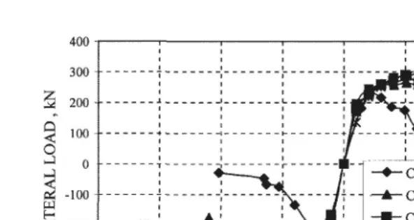
The strength envelope, which is the relationship between the peak load at each cycle and the corresponding displacement, is presented for the tested columns in Figure 12. The lateral strength increases considerably for all the wrapped specimens.
The highest strength was that of specimen C2 with two CFRP wraps, 46% higher than the control column. Specimen C3, with one layer of CFRP, produced the lowest increase which was 20% higher than the control column. This increase in the flexural strength is attributed to the confinement provided by CFRP which resulted in an increase in the concrete strength and strain. It should also be noted that the longitudinal reinforcement bars reached the strain hardening, consequently the stress in the steel bars exceeded the yield stress leading to an increase in the overall strength of the retrofitted columns.
400
300
2 200
o
J
0
2 -100 w
< -200 -300 - • -400
•
1
- - i 1
J _ ... ^ J l r ^ * > v
ml
i\ \ i i V i V i
- • - C l Control • A C3 with one sheet
M C5 one sheet with steel plates —•— Ot continuous wrapping
X C2double wrapping
. . i
-40 -30 -20 -10 0 10 20 LATERAL DISPLACEMENT, mm
[image:8.612.88.384.70.227.2]30 40
Figure 12 Hysteresis loops envelope of lateral load against displacement
Yield Displacement
The yield displacement Ay of an equivalent elasto-plastic system with reduced cracked
stiffness was calculated from the lateral load-displacement curve as the corresponding displacement at the intersection of the secant stiffness at a load level of 75% of the ultimate lateral load and the tangent at the ultimate load. The strength envelope is used to determine the yield displacement [3].
Displacement Ductility Factor
The failure load was taken equal to 75% of the ultimate load on the descending branch on the strength envelope and the corresponding displacement Af was computed. The displacement ductility factor is defined as the ratio between the displacement at failure load, Af, and the yield displacement, Ay as given by Equation (1).
Displacement Ductility factor = Af /Ay (1)
The control column failed in a brittle shear mode at a low ductility factor of 2.3 as shown in Table 3. All the strengthed columns failed in a ductile mode with ductility factors more than 4.5. It should be noted that the satisfactory level of ductility is achieved by a minimum of ductility factor of 3 [4]. Specimen C2 with double layer produced the highest value of ductility factor (3 times that of Cl).
Behaviour of Retrofitted CFRP Columns 347
Table 3 Ductility analysis and energy index
SPECIMEN
Cl C2 C3 C4 C5
YIELD DISPLACEMENT,
Ay mm
2.85 4.40 3.94 4.10 4.85
FAILURE DISPLACEMENT Af
mm 6.75 31.91 18.91 26.42 25.80
DUCTILITY FACTOR Af/Ay
2.36 7.25 4.78 6.44 5.31
ENERGY INDEX
8.9 204.3
66.3 122.9 114.5
Energy Dissipation
The dissipated energy was computed for each cycle as the area enclosed by the lateral
load-displacement hysteresis loop for the given cycle. The accumulated dissipated energy is
plotted versus the lateral displacement for the tested specimens in Figure 13.
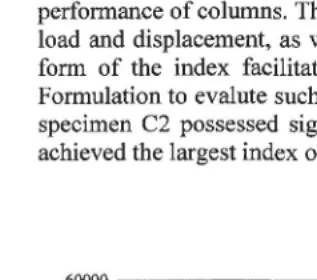
A non-dimensional energy index based on Ehsani [5] was also used to evaluate the energy
dissipated for the tested specimens. The index appears to be a reliable indicator of the
performance of columns. This is due to the fact that it accounts for the cracked stiffness, yield
load and displacement, as well as the dissipated energy of each cycle. The non-dimensional
form of the index facilitates the comparison of specimens of different sizes and scales.
Formulation to evalute such index is explained in [5].Compared with the retrofitted columns,
specimen C2 possessed significantly larger energy dissipation than the other columns as it
achieved the largest index of 204. Column C3 had the lowest index of 66.
60000
0 5 10 15 20 25 30 LATERAL DISPLACEMENT,mm
0 5 10 15 20 25 30 LATERAL DISPLACEMENT,mm
Figure 13 Accumulated energy
[image:9.612.61.220.406.546.2] [image:9.612.239.406.407.542.2]Stiffness Analysis
The cracked stiffness of each tested specimen, Ki, is calculated for every loading cycle. The cracked cycle stiffness is computed as the ratio of the sum of the peak tension and compression loads to the sum of the corresponding tension and compression displacements as illustrated in [1]. It can be seen from Figure 14 that the initial stiffness of all columns including the control one was approximately the same. At high load levels, the retrofitted columns showed higher stiffness than that of the control column. This presents a good advantage of the CFRP wrapping technique, as the strengthed columns will not attract more horizontal force at low load levels during any seismic loading. Also, a close examination of these plots indicates that the rate of stiffness deterioration of the retrofitted columns under large reversed cyclic oading was lower than that of the control column.
CONCLUSIONS
CFRP wraps showed an excellent enhancement to the overall behavior of the columns and the following conclusions can be summarized for the studied cases:
1. All the wrapped specimens failed in a ductile flexural mode, instead of the brittle shear mode of the original column.
2. Increasing the CFRP volumetric ratio improved the overall behaviour of the column and increased the lateral strength. However, it is recommended that the number of layers be increased instead of reducing the spacing between the layers.
3. It was observed that the behaviour of columns C4 and C5 was similar although the CFRP ratio was 50% less for column C5. This suggests that a proper choice of the anchorage system may be more feasible than reducing the spacing between sheets. 4. Unlike the conventional techniques for column strengthening, the initial stiffness of the
retrofitted columns was similar to that of the original one.
REFERENCES
1. SAADATMANESH, H., EHSANI, M., AND JEST, L. (1997) " Repair of Earthquake-Damaged RC Columns with FRP wraps ", ACI structural Journal, V. 94, No. 2.
2. HOSNY, A., SHAHEEN, H., ABDELRAHMAN, A., AND EL-AFANDY, T. (2002) " Strengthening of Rectangular RC Columns Using CFRP", M.Sc.Thesis, Faculty of Eng. Ain Shams Univ.
3. PARK, R., AND PAULAY, T. (1975) " Reinforced Concrete Strucrutes" , John Wiely and Sons, New York, N.Y.
4. PRIESTLY, M., AND PARK, R. (1986) " Strength and Ductility of Concrete Bridge Columns under Seismic Loading", ACI Structural Journal, V. 84, No. 1.