UNIVERSITI TEKNIKAL MALAYSIA MELAKA
PROJECT TITLE: OPTIMIZATON OF REAR SUSPENSION
DYNAMIC PERFORMANCE BY USING VIRTUAL FORMULA
This report submitted in accordance with requirement of the Universiti
Teknikal Malaysia Melaka (UTeM) for the Bachelor Degree of Engineering
Technology (FTKM)
By
STUDENT NAME: MUHAMMADAMIR FUAD BIN MUHALITH
MATRIX NUMBER: B071310173
IC NUMBER: 910215045349
i
DECLARATION
I hereby, declared this report entitled “OPTIMIZATON OF REAR SUSPENSION DYNAMIC PERFORMANCE BY USING VIRTUAL FORMULA” is the results of my
own research except as cited in references.
Signature : ………
Author’s Name : Muhammad Amir Fuad Bin Muhalith
ii
APPROVAL
This report is submitted to the Faculty of Engineering Technology of UTeM as a partial fulfillment of the requirement for the Degree of Engineering Technology (Automotive
Technology) with Honors. The member of the supervisory is as follow:
iii
ABSTRAK
iv
ABSTRACT
v
DEDICATION
vi
ACKNOWLEDGEMENT
Firstly, I am grateful to the Allah S.W.T for the good health and well being that were necessary to complete this PSM project. I have completed this project even though there are many difficulties during the project occur.
I wish to express my sincere thanks to my supervisorMr. Mohd Hafizi bin Abdul Rahman for sharing expertise and valuable guidance during the project. Thank you also for the consistence guidance and support during my project writing is invaluable to me and continuous direction and opinion regarding the flow of the project has invaluable contribution to achieve the objectives of this project.
I take this opportunity to express gratitude to all of the department faculty members for their help and support. I also thank my parents for the encouragement, support and attention. Their support is meant so much to me in finishing this report.
vii
TABLE OF CONTENT
Abstrak iii
Abstract iv
Dedication v
Acknowledgement vi
Table of content vii List of Figures x List of Tables xii
List of Abbreviations, Symbols and Nomenclatures xiii
CHAPTER 1: INTRODUCTION 1.0Introduction 1
1.1Problem Statement 2 1.2Objective 2
1.3Scope 3
CHAPTER 2: LITERATURE REVIEW 2.0 Introduction of suspension 4 2.1 Type of Suspension 5
2.1.1 Double Wishbone 5
2.1.2 Pushrod Suspension 9
2.2 Parameter Involve in Suspension 13
2.2.1 Camber angle 14
viii
2.2.3 Spring Stiffness 18
2.2.4 Anti-Roll Bar 19
CHAPTER 3: METHODOLOGY 3.0 Introduction 22
3.1 Software VI-Grade 22
3.2 Rules and Regulation 23
3.3 Research Design 23 3.4 System Selection 25
3.5 Parameter Selection 25 3.6 Simulation Testing 25 3.7 Optimization 26
3.7.1 Suspension 26
3.7.1.1 Spring stiffness 27
3.7.1.2 Jounce Start and Jounce End (Damper) 28
3.7.1.3 Camber Angle 29
3.7.1.4 Anti-Roll Bar 30
CHAPTER 4: RESULT AND DISCUSSION 4.0 Introduction 31
4.1 Software Setup 31
4.2 Virtual Race Track Analysis 32 4.3 Suspension Result and Discussion 33 4.3.1 K spring 34
ix
4.3.3 Camber Angle 44
4.3.4 Torsion Stiffness 47 4.3.5 Summary 51
CHAPTER 5: CONCLUSION 5.0 Conclusion 52
5.1 Problem and Limitation 53
5.2 Recommendation 53
APPENDICES 55
x
LIST OF FIGURES
Figure 2.1: A First Type Coil is Mount (Güler, 2006) 6
Figure 2.2: A Second Type Coil is Mount (Güler, 2006) 6
Figure 2.3: Equal length Double Wishbone and parallel (Unlusoy, 2000) 7
Figure 2.4: Unequal Double Wishbone and parallel (Unlusoy, 2000) 8
Figure 2.5: Unequal Double Wishbone and parallel (Unlusoy, 2000) 8
Figure 2.6: Position of Pushrod is Mount (www.locostusa.com) 10
Figure 2.7: Pushrods Suspension System Configuration (www.f1fanatic.co.uk) 10
Figure 2.8: Toe Link position in Double Wishbone (Moto-concept.de) 11
Figure 2.9: left and rear view of the wheel and its suspension Showing the Force line runs through tire contact Patch (van de Bos, 2010) 12
Figure 2.10: Pushrod Actuated Shock Design (www.pinterest.com) 12
Figure 2.11: Direct Acting Shock Design (thefactoryfiveforum.com) 13
Figure 2.12: Contact surface of the tires with a camber angle position (performancetrends.com) 14
Figure 2.13: Figure 2.13: Positive and Negative camber angle position (www.vikingspeedshop.com) 15
Figure2.14: The Graph of Lateral Force versus Camber angle (Fundamentals of Vehicles Dynamic” Gillespie 1997; pg127) 16
Figure 2.15: Jounce and Rebound of the damper (Formula1-dictionary.ne) 17
Figure 2.16: Anti-Roll Bar Position (speed. Academy) 20
xi
Figure 3.1: System selection Flow 25 Figure 4.1: VI-Grade Virtual Track) 33 Figure 4.2: List Type of Suspension 36 Figure 4.3: Graph of Time Laps vs. Rear K Spring
(Lower Upper Control Arm) 36
Figure 4.4: Graph of Time Laps vs. Rear K Spring
(Double Wishbone with Push Rod & U-bar) 37
Figure 4.5: Graph of Max Speed vs. K Spring
(Lower Upper Control Arm) 38
Figure 4.6: Graph of Max Speed vs. K Spring
(Double Wishbone with Push Rod & U-bar) 38
Figure 4.7: Graph of Time Laps vs. Rear Jounce Start
(Lower Upper Control Arm) 41
Figure 4.8: Graph of Time Laps vs. Rear Jounce End
(Lower Upper Control Arm) 41 Figure 4.9: Graph of Time Laps vs. Rear Jounce Start
(Double Wishbone with Push Rod & U-bar) 42 Figure 4.10: Graph of Time Laps vs. Rear Jounce End
(Double Wishbone with Push Rod & U-bar)) 43
Figure 4.11: Graph of Max Speed vs. Rear Jounce
(Lower Upper Control Limit) 43 Figure 4.12: Graph of Max Speed vs. Rear Jounce
(Double Wishbone with Push Rod & U-bar) 44 Figure 4.13: Graph of Time Laps & Max Speed vs. Camber Angle
(Lower Upper Control Arm) 46
Figure 4.14: Graph of Time Laps & Max Speed vs. Camber Angle
(Double Wishbone with Push Rod & U-bar) 47
Figure 4.16: Graph of Time Laps & Max Speed vs. Camber Angle
xii
LIST OF TABLES
Table 3.1: Default Parameter of LUCA and Double Wishbone
with Push Rod & U-bar 27
Table 3.2: Default Parameter of LUCA and Double Wishbone with Push Rod & U-bar 28
Table 3.3: Jounce Start and Jounce End 29
Table 3.4: Camber Angle 30
Table 3.5: Torsion Stiffness 31
Table 4.1: Parameter and Result of Default Suspension 34
Table 4.2: Result of Time Laps and Maximum Speed for K spring 36
Table 4.3: Result of Time Laps, Maximum Speed and Fuel consumption for Jounce Start and Jounce End for the both type of suspension 40
Table 4.4: Result of Time Laps and Maximum Speed for Camber Angle 45
Table 4.5: Result of Time Laps & Maximum Speed of Camber Angle (Double Wishbone with Push Rod & U-bar) 47
Table 4.6: Result of Time Laps and Maximum Speed of Torsion (Lower Upper Control Arm) 49
Table 4.7: Result of Time Laps and Maximum Speed of Camber Angle (Double Wishbone with Push Rod & U-bar) 50
xiii
LIST OF SYMBOLS ANDABBREVIATIONS
LSD Limited Slip Differential
DOE Design of Experiment
FIT Approximation
RSM Response Surface Method
LSR Least Squares Regression
MLSM Moving Least Squares Method
HK Hyper Kriging
RBF Radial Basic Function
1
CHAPTER 1
INTRODUCTION
1.0 Introduction
2
1.1 Problem Statement
The suspension system that commonly used on the racing car are usually have a fixed parameter which is difficult to tune in order to achieve high performance and might be far away from its optimum setting. Therefore, to test the suspension on the real car would cost a lot of money and time. There is many software can be used such as ADAMS, Carsim and MatLab. Currently there is new Multi-Body Simulation (MBS) software named VI-Grade in the market which is more accurate, variety of setup and also due to its flexible parameters that can be change easily. VI-Grade offer more parameter that can be tested and the result is more precise and in-depth compare to the other software. VI-grade competition gives the default model and its must optimize the default model in order to get the better result from default model. To optimize the default model it must follow the rules and regulation in vi-grade virtual formula. It must refer the other journal to know the method need to use to get the best setup. In Grade virtual formula it’s give the Vi-Grade software, the software can tune the parameter and test directly in virtual formula race track. The software can help to understand the problem and can give the correct value or setting to parameter.
1.2 Objective
The objective is:
1. To get the best lap time, maximum speed and low fuel consumption.
2. Performed DOE analysis on RR suspension to get the optimum value of max
3
1.3 Scope
The scope are:
1. Optimize the rear suspension characteristic to achieve the best lap time. 2. Only involve simulation using the software vi-grade.
3. Other specification is according to default.
4
CHAPTER 2
LITERATURE REVIEW
2.0 Introduction of suspension
Suspension that include tires, tire air, springs, shock absorbers and linkages that connects a vehicle to its tires and allows comparative movement between the two. Suspension systems serve a dual purpose contributing to the vehicle's road holding/handling and avoiding completely efficient safety and driving pleasure, and keeping vehicle occupants comfortable and a quality of drive reasonably well separated from road disturbance, bumps, and vibrations. It is important for the suspension to keep the wheel get in contact with surface much as possible, because all the road or ground forces operating on the car do so through to get in contact with patches of the tires. The suspension also protects the vehicle itself and any shipping or luggage from damage, broken and wear.Suspension system is generally designed in relationship with the steering system. (Chinmaya Acharya, 2014)
5
generally not an interference problem since most of the component to Stiff portion of the chassis to correctly distribute the load that will be passed through these components (Edmund et al. 1996).
- In vehicle suspension system it consists of wishbone, spring stiffness and the absorber that is used to absorb, transmit and filter all forces between the road and body. Spring stiffness responsible to carry the body mass separately the chassis from the road that lead to comfortable of driving. Similarity damper is used to achieve driving safety and driving comfort (Edmund et al, .1996).
2.1 Type of Suspension
Type of suspension used for this literature review is double wishbone and solid axle. Each type of suspension has their own function and will be discussed in details in this chapter.
2.1.1 Double Wishbone
6
The geometry of double wishbone suspension system design with spring and absorber to give an importance role to improve the stability of the vehicle. This suspension also gives more stability to the movement during the high speed, where the camber angle can be reducing as the wheel is moving in rough surface road (Patil, 2013). This adjustment for this type of suspension is easy, the parameter such as camber can be adjusting, it will give the camber angle to become more negative (Vivekananda et al., 2014).
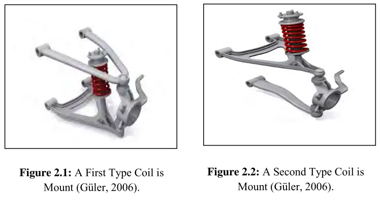
The design of the coil spring will give advantage to the suspension system. There are two type of technique for coil spring is mounting. First, the spring located between frame and lower control arm as shown in figure 2.1. In this case, most of the load was carried by the lower arm. Second type of mounting where the spring is located between upper control arms. Second types of mounting where the spring is located between upper control arms and above of the frame as shown in figure 2.2. Upper arm and the spring mount to absorb almost the load. However, the second type is not popular since it is consuming a lot of space (Güler, 2006).
[image:20.612.140.514.408.613.2]
There are advantages when using the unequal length of double wishbone suspension system. Unequal length of double wishbone suspension is used to maintain stabilization and have suitable center (Shun-Kai et al. 2006).
Figure 2.2: A Second Type Coil is
Mount (Güler, 2006).
Figure 2.1: A First Type Coil is
7
Unequal length of double wishbone suspension also can maintain good traction between the roads and tire to reduce the interference between suspension and steer bar. With the proper structural parameter and arrangements, it affects the parameter of wheel spin and wheel location floating in permissible range. For formula SAE car, stabilization with high speed is more important than the ride the comfort (Liu et al., 2013).
To reach maximum grip when cornering, suspension plays important roles to keep the tires perpendicular to the ground under the entire condition road surface including bumps so the contact patch area between area between tire and ground is maintained at its maximum. Generally double wishbone suspension does the job well for keeping the tire perpendicular to the ground (Attia et al., 2001).
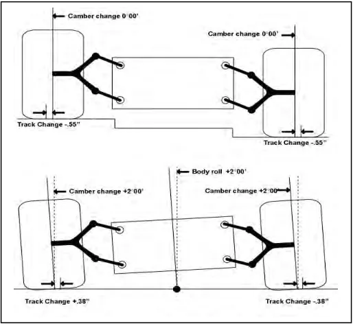
[image:21.612.205.462.411.647.2]Double wishbone suspension has three type of arm. The first one is the wishbone are equal length and parallels shown in Figure 2.3. The second one is the wishbone with unequal length and parallel suspension system as shown in Figure 2.4. Lastly, unequal length and non-parallel wishbone suspension system as shown in Figure 2.5 (Unlusoy, 2000).
8
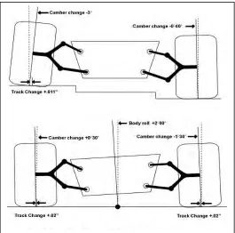
Figure 2.4: Unequal Double Wishbone and parallel (Unlusoy, 2000)
[image:22.612.201.466.393.655.2]9
Refer to figure 2.3, the equal length of arm and parallel in double wishbone suspension, camber has no change under bump but when there is some change in boy roll, camber changes same degree as the body roll. If the body rolls change in 2 degrees, camber also follows the same degree change; the changing of camber will reduce the contact patch area between the tire and ground. The tires tend to be slip and the gripping will reduce. Then, unequal length double wishbone a parallel was invented by engineers, the changing of camber and track width give huge effect of reducing the body roll, but under bump there are some small trade –off in wheel control as shown in Figure 2.4. For unequal length a non-parallel double wishbone, camber angle during heavy loaded does not much effect the outsides wheel an also it is not too good under the bumpy surface as shown in Figure 2.5 (Unlusoy, 2000).
2.1.2 Pushrod Suspension
10
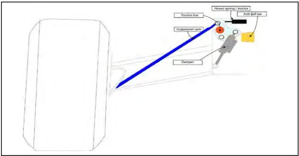
Figure 2.6: Position of Pushrod is Mount (www.locostusa.com)
There is other alternative for a race car suspension;one of them is a pushrod system. This system is widely used in many race car, it is because of the positioning and adjustment can be made easily. The pushrod was mounted below the lower A-arm position together with a bell crank near the top of the frame which can be seen on Figure 2.6. There are a few ways to mounted the damper, one of the way is by mounted in a vertically position. The pushrod is installed at the upper or lower A-arm. The rod is specially made by a carbon and coated with aluminum to hold the rod end. Furthermore, the strength and the stiffness of the rod can be achieved in a high level of compression and tension. However, it cannot stand from bending (Van Den Bos, 2001).
[image:24.612.190.490.491.648.2]