Design Optimization of a Lower Control Arm
of Suspension System in a LCV by using
Topological Approach
Swapnil S. Khode1, Prof. Amol N. Patil2, Prof. Amol B. Gaikwad3
P.G. Student, Department of Mechanical Engineering, Dr. D. Y. Patil School of Engineering Pune, Maharashtra, India1 Professor, Department of Mechanical Engineering, Dr. D. Y. Patil School of Engineering Pune, Maharashtra, India2 Professor, Department of Mechanical Engineering, Dr. D. Y. Patil School of Engineering Pune, Maharashtra, India3
ABSTRACT: The most important component in vehicle is a suspension system, which directly affects the safety, performance and noise level. The unsprung mass is the mass of the suspension components which is directly connected to them, rather than supported by the suspension. High unsprung weight exacerbates issues like wheel control, ride quality and noise. Unsprung weight includes the mass of components such as the wheel axles, wheel bearings, wheel hubs, springs, shock absorbers, and Lower Control Arm. The lower control arm is a wishbone-shaped metal strut that attaches the wheel to the vehicle's frame. Different optimization techniques under various load conditions have been widely used in automobile sector for lightweight and functioning enhancement. This study deals with Finite Element Analysis of the Lower control arm of Mac-pherson suspension system and its optimization under static loading condition. The existing design of lower control arm from one of the light commercial vehicle is selected for the study. In order to determine the deformation and stress distribution in the current design, the finite element analysis is carried out. The main aim of this paper is to optimize the lower control arm of Mac-pherson suspension system under the current boundary conditions for weight reduction. The baseline model of the lower control arm is created by using solid modeling software viz. CATIA. ANSYS Workbench is used for Finite Element Analysis and OPTISTRUCT solver module is used to generate the optimized model. The present study is used to reduce the weight and cost of the lower control arm by keeping the factor of safety within permissible limits. The weight reduction in one lower control arm is observed to be 17.5%.
KEYWORDS: FEA, LCA, Optimization, Topology.
I. INTRODUCTION
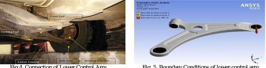
steering vibration. The control arm is prominent component of McPherson Strut Suspension nearly flat and roughly triangular member, that pivots in two places. The broad end of triangle is attached at the frame and pivots on bushing. The narrow end attaches to the steering knuckle and pivots on the ball joint [5]
II. LITERATURE REVIEW
A short history of suspension field has been documented in the present review. It reviews early development of various types of suspension system such as double-wishbone suspension, Mac Pherson Strut suspension. It also reviews design and developments, simulation analysis for a vehicle suspension system. According to Christianah O. Ijagbemi [2] et al. “Design and simulation of fatigue analysis for a vehicle suspension system (VSS) and its effect on global warming” 9 June 2016, this study shows that for every gallon of gasoline burnt, 12.7kg of CO2 is released. Fuel economy improvement is almost linear with a reduction in weight of a car. Therefore, reducing vehicle weight results in less fuel consumption and a decrease in CO2 emission which in turn has an effect on global warming. Car manufacturers are facing increasingly stringent CO2 emission standard. In this paper, an investigation was carried out on vehicle suspension system (VSS) by employing Finite Element Analysis (FEA) to analyze the fatigue life, von misses stress, factor of safety and stability of the suspension system and how the weight and size can be reduced.
According to VinayakKulkarni [3] et al. “Finite Element Analysis and Topology Optimization of Lower Arm of Double Wishbone Suspension using RADIOSS and Optistruct” May 2014, this paper deals with calculating the forces acting on lower wishbone arm while vehicle subjected to critical loading conditions. Suspension geometry and suitable materials for the suspension arm has been identified. Lower arm suspension has been modeled using Pro-Engineer. Von mises stress –strain is carried out in order to find out maximum induced stress and strain. These analysis were carried using Altair Hyperworks and solver used is Radioss. From the analyzed results, design parameters were compared for two different materials and best on was taken out. From result obtained it was found that current design is safe and is somewhat overdesign. So in order to save material and reduce weight of component, Topology optimization analysis is carried out in Hyperworks which yielded in optimized shape. The higher factor of safety leads to optimization of component. Topology optimization generates an optimized material distribution for a set of loads and constraints within a given design space. Optimization reduces weight, product design cycle time and cost.
From the previous studies, it can be noted that, even though several works are filed on Wishbone and Mac pherson suspension, most of the work are focused on improvement of efficiency and performance
III.PROBLEM DEFINITION AND OBJECTIVE
The unsprung weight of a wheel controls a trade-off between a wheel's bump-following ability and its vibration isolation. A heavier wheel which moves less will not absorb as much vibration; the irregularities of the road surface will transfer to the cabin through the geometry of the suspension and hence ride quality and road noise are thus worse. For longer bumps that the wheels follow, greater unsprung mass causes more energy to be absorbed by the wheels and makes the ride worse. High unsprung weight also complicate wheel control issues under hard acceleration or braking. The high unsprung mass can lead to severe wheel hop, compromising traction and steering control. This is unsprung weight which increase the overall weight of suspension system and finally of vehicle. Also it effects on performance & efficiency, handling capabilities. It also has substantial impact on emissions control as well as overall cost.In order to solve above mentioned problem, main aim of the project is summarize below:
To optimize the lower control arm for weight reduction” (unsprung weight) upto 15-20% and suggest alternate design.
To carry out static structural analysis of existing model using FEA based software ANSYS workbench.
To carry out topological optimization of lower control arm by OPTISTRUCT solver.
To compare the factor of safety for optimized and baseline design of lower control arm by keeping factor of safety for optimized design within permissible limits.
To validate the FEA and Experimental results.
IV.THEORETICAL ANALYSIS
A. The dimensions of Lower Control arm
Dimension of Lower Control Arm is as follows:Overall length is 463mm, width is 241.9mm and thickness is 3mm
B .The material properties of steel
The material is AISI 1040, which is having all these characteristics. TABLEI MATERIAL PROPERTIES
Material AISI 1040 Young’s modulus 2.1e5MPa Poisson’s ratio 0.3
Density 7850Kg/m3 Yield strength 415MPa Tensile strength 620 MPa
C. Static Load calculation of Lower Control Arm
Gross Weight of Wagon R =1350 Kg (considering passengers and accessories weight),Total Weight in Newton W = 1350 x 9.81=13243.5 N. It is assumed that 52% of weight taken by front axle, due to mounting of engine on front side and remaining 48% weight taken by rear axle. Therefore,Weight on Front axle(F1) = 0.52 x 13243.5 N= 6886.62 N
Weight on Rear axle(F2) = 0.48 x 13243.5 N = 6356.88 N.Reaction at each front wheel,Rw= Weight on Front
axle/2= 6886.62/2=3443.31 N. This load is constituted by spring, stub axle and lower control arm. While stub axle of the wheel takes 50% of the total load acting on each wheel. Therefore, force acting on the stub axle of wheel is given by,F= 1721.6 N. Following line diagram is a representation of the spring, and lower arm.
Fig.1. Line diagram for force distribution Where,
R1=Reaction for spring in Newton.,R2=Reaction for lower arm in Newton.,F = Force acting on stub axle in Newton
Therefore, from equilibrium condition, taking moment at A is equal to zero.∑MA = 0, We get, R2 =765.15 N .This is
vertical load acting on the lower control arm.Now, R1 + R2 =F,Hence R1 =956.45 N.This reaction is acting vertically
upward at spring.Therefore, the Reaction R2 = 765.15 N. Approximately taken as R2≈765N, which is acting in
V. FINITE ELEMENT ANALYSIS
ANSYS software is used to mesh the solid model. CAD model which is in IGES format is imported to ANSYS.
Fig. 2. Baseline Lower Control Arm for FEA Fig. 3. Meshing of Lower Control Arm
A. Meshing of baseline geometry
The conventional model which was developed in CATIA software has to be meshed for analysis. For this ANSYS workbench software is used. It is a high-performance finite element pre-processor that provides a highly interactive and visual environment to analyze product design performance. With the broadest set of direct interfaces to commercial CAD and CAE systems. The solid tetrahedron elements are used to generate the meshing of the control Arm.
TABLE II DETAILS OF MESHING
Sr. No. Description Values 1 Number of Nodes 53002 2 Number of Elements 26694
3 Element Size Maximum 5 mm Minimum 3 mm
B. Design parameters
In case of vehicle in actual running conditions forces acting on it are of dynamic in nature and changes as per driving conditions. In order to make preliminary analysis steady state operating conditions are assumed.
C. Boundary conditions of baseline geometry
to tie rod of steering mechanism and lower arm is connected to wishbone or lower control arm by a ball joint. The other two ends of LCA are connected to chassis frame, out of which one is fixed and other end turn about a pivot.
D. Analysis Result of Baseline model
After Finite Element analysis on ANSYS workbench 18.0 following results have been find out. The displacement contour plots are shown in the below figure10.
Fig. 6. Maximum Deformation Plot Fig.7. Equivalent Stress Plot Fig.8. Safety factor
The maximum displacement shown by the baseline lower control arm is 8.32 mm.The above figure 6 shows contour plot of the von-Mises stressAs per distortion energy theory, the maximum equivalent stress observed in the lower arm model is 512 MPa.The tensile strength of the material is 620 MPa. According to results, the von-Mises stress 512 MPa is lower tensile strength of the material. The factor of safety of the baseline lower Arm is 1.21.Mass of the Baseline design = 1.2 Kg
D. Topology Optimisation by FEA
Topology Optimization is defined as finding out the best possible solution of problem by considering the given sets of objective and number of constraints. For solving any topology optimization problem it have to specify three parameters that is Design Variables (material density), Design objective (Weight reduction) and design constraints (Volume)[6].Topology optimization is performed on a model to create a new topology for the structure, removing any unnecessary material. The resulting structure is lighter and satisfies all design constraints.
The topology optimisation of control arm model is carried out in OPTISTRUCT software. The Material data for carbon steel remain same as used in the static structural analysis. The optimisation model includes same boundary conditions as used in the static analysis of baseline model. Topology optimization carried out for the following objective
Objective To minimize volume (reduce weight)
Constraints von-Mises stress < 620 MPa (Tensile strength of material) Design Variables The density of each element in the
design space.
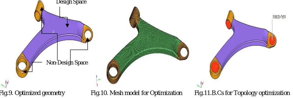
E. Optistruct Model
design space and nondesign Space. The design space is the region where design optimisation will be carried out. The nondesign space is the region where, no design change will be done by the software.
Fig.9. Optimized geometry Fig.10. Mesh model for Optimization Fig.11.B.Cs for Topology optimization The optimised CAD model is meshed in HYPER MESH with CTETRA elements is shown in above figure
TABLE III DETAILS OF MESHING
Sr. No. Description Values 1 Number of Nodes 32537 2 Number of Elements 98130 3 Element Size 2 mm
The rigid body motion of the Lower control arm are restrained by constraining the faces of the holes where it is fixed with the screw connections as shown in the figure below in red colour region. The x, y, z translation and ROTX, ROTY, ROTZ rotations are fixed in all directions.
F. Analysis result for optimised model
The element density plots shows the optimized pattern of the model. The white region in lower control arm indicates the unnecessary material to be removed from the design. The optimized design is extracted from the raw design obtained through analysis. The optimized design is prepared in the CATIA software.
Fig.12. Element Density Plot Fig.13. Element Density Contour Plot
Design Space
Above figure shows that low stess blue region can be removed from the design space while keep the red region in the design space as it is. Mass of the optimised design is obsereved to be 0.99 Kg. The total reduction in mass is observed by 17.5%. Since, Mass of the model is decreased from 1.2 Kg to 0.99 Kg. As per Element Density plot new optimized LCA model is designed in CATIA and it is analysed in ANSYS for same boundary and loading conditions.
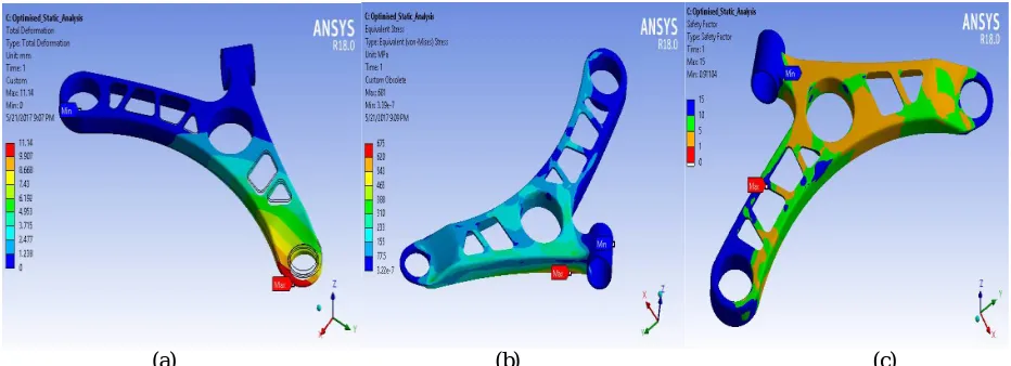
(a) (b) (c)
Fig.14. (a)Deformation Plot - Optimized design, (b) Max. von-Mises stress, (c)Safety factor for optimized design The maximum deformation for the optimised design is observed up to 11.14 mm.The von-Mises stress is observed upto 555Mpa for optimised model.Factor of safety of optimized model=620/555=1.11
VI.EXPERIMENTAL ANALYSIS
Universal testing machine also known as Universal tester or material testing machine which is used to test the tensile strength and compressive strength of materials. For mounting of LCA on UTM for testing, proper fixture has been design. Following figure shows assembly of LCA and fixture
.
(a) (b) Fig. 15(a)Fixture, (b) Experimental Setup
by using of load cells of universal testing machine. The peak 765N load is applied on both arm models to find out deflection value on that peak load. A deflection value for the baseline arm is 7.7 mm and for new model is 10.4 mm.
VII. RESULTSANDDISCUSSION
Static analysis of existing and modified LCA is carried out by experimentally and Finite element method. Following graph shows the results of both model by Finite element method.
(a) (b) (c)
Fig.16.(a) Graph plot of Force vs.Deflection, (b) Plot of Stress vs.Deflection,(c)Graph plot of Safety factor vs. Force
From the above graph it is observed that deformation of a optimized model as compared to baseline model is varies upto 11.14mm with the gradual application of load, maximum stress induced in both model is below the ultimate tensile strength of material. This indicates that design is safe for the applied load, also it is observed that there is a increase in stress occur in optimized model due to reduction in mass but this increased stress is below the ultimate limit.
Above graph shows that there is slight variation in factor of safety by 10% can leads to 17.5% reduction of mass of single lower control arm.Total weight reduction in one control arm is found to be 210gm. There is presence of two lower control arm in Mac pherson suspension system. So overall weight reduction in front suspsension system is 420gm.The cost of AISI 1040 is Rs.51.36 per Kg. According to this baseline lower control arm(LCA) of 1.2Kg requires material of Rs.61.95 whereas optimized LCA of 0.99 Kg requires material of Rs.51.11. So total cost saving in material of one arm is as follows
CT= CB-CO=61.95-51.11=Rs.10.84
Where, CT = Total cost saving in material of one arm.CB = Cost of material for baseline LCA.CO = Cost of material for
optimized LCA.Let say in mass production company manifactures 1000 parts per week, so total cost saving per 1000 parts will be Rs.10842.75 which is good achievement in company prospective.
0 200 400 600 800 1000
0 5 10 15
Fo rc e , N Deflection, mm Baseline-Force Vs Deflection 0 200 400 600
0 5 10 15
St re ss , M P a Deflection, mm
Baseline- Stress Vs Deflection
UltimateTensile Strngth=620 MPa
0 5 10 15 20
0 500 1000
Sa fe ty fa ct o r Force, N
Baseline-Safety Factor Vs Force
TABLEIV RESULT ANALYSIS
Sr. No. Method Description Baseline Design Optimised Design 1
ExperimentalMethod
Deflection, mm 7.7 10.4 2 Von-Mises stress, MPa 475 520
3 Mass, Kg 1.20 0.99
4
FEAMethod
Deflection, mm 8.33 11.14 5 Von-Mises stress, MPa 512 555
6 Mass, Kg 1.20 0.99
7 Theoretical analysis Factor of Safety 1.21 1.11 VIII. CONCLUSION
As deflection and stress of modified LCA is within the range. Thus, the modified design is safe. Weight of the final optimized model is 0.99 kg. The total reduction in mass is observed 17.5% by keeping Factor of safety for optimized design within permissible limits. Thus the objective of weight reduction of unsprung mass and cost reduction has been achieved.
ACKNOWLEDGMENT
I take this opportunity to thanksProf. A. N. PatilandProf A. B. Gaikwad for valuable guidance and for providing all the necessary facilities, which were indispensable in completion of this work.
REFERENCES
1.Nikita Gawai et al. “Design, Modeling& Analysis of Double Wishbone Suspension System “International Journal on Mechanical Engineering and Robotics (IJMER) ISSN (Print) : 2321-5747, Volume-4, Issue-1,2016.
2.Christianah O. Ijagbemi et al. “Design and simulation of fatigue analysis for a vehicle suspension system (VSS) and its effect on global warming” Humanitarian Technology: Science, Systems and Global Impact 2016, HumTech2016, 7-9 June 2016, Massachusetts, USA.
3.VinayakKulkarni et al. “Finite Element Analysis and Topology Optimization of Lower Arm of Double Wishbone Suspension using RADIOSS and Optistruct” International Journal of Science and Research (IJSR) ISSN (Online): 2319-7064 Volume 3 Issue 5, May 2014
4.SagarDarge et al. “Finite Element Analysis and Topography Optimization of Lower Arm of Double Wishbone Suspension Using Abacus and Optistruct” International Journal of Engineering Research and Applications www.ijera.com ISSN : 2248-9622, Vol. 4, Issue 7( Version 6), July 2014, pp.112-117.