Author for Correspondence:
1PG Scholar,CAD/CAM Engineering, KSR Institute For Engineering & Technology, Tiruchengode, Tamilnadu,
India.
APR-2015
International Journal of Intellectual Advancements
and Research in Engineering Computations
ANALYSIS AND OPTIMIZATION OF LOWER CONTROL ARM USING
FRONT SUSPENSION SYSTEM
1
S.Suresh
,
2P.Manikandan
ABSTRACT
Suspension systems are used to provide good ride and handling performance in providing chassis isolation of vertical compliance. It ensures that the wheels follow the road profile with little tire load fluctuation. Suspension steering control is maintained during maneuvering wheels to be maintained in proper position. It achieves longitudinal braking, accelerating forces, lateral cornering forces, braking and accelerating torques responds favorably to control forces produced by the tires. It prevents the transmission of „road noise‟ to the vehicle body so that it requires appropriate isolation in the suspension joints to provide isolation from high frequency vibration from tire excitation. The design has been modified by reducing the thickness of profile. It accomplishes the optimization that would placate customer‟s anticipations.
INTRODUCTION
The suspension system caries the vehicle body and transmit all forces between the body and the road without transmitting to the driver and passengers. The suspension system of a car is used to support its weight during varying road conditions. The suspension system is made of
several parts and components. These include the front and rear suspensions, the shock absorbers, and the Macpherson strut system. The suspension system is further classified into two subgroups, dependent and independent. These terms refer to
the ability of opposite wheels to move
independently of each other.
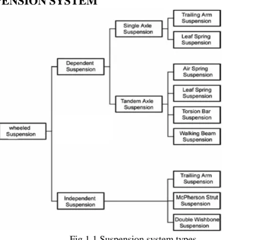
TYPES OF SUSPENSION SYSTEM
Fig 1.1 Suspension system types
DEPENDENT SUSPENSION SYSTEM
A dependent suspension normally has a beam (a simple 'cart' axle) or (driven) live axle that holds wheels parallel to each other and perpendicular to the axle. When the camber of one wheel changes, the camber of the opposite wheel
changes in the same way (by convention on one side this is a positive change in camber and on the other side this a negative change). De Dion suspensions are also in this category as they rigidly
connect the wheels together.
Fig 1.2 Hotchkiss suspension and trailing arm suspension
INDEPENDENT SUSPENSION SYSTEM
Fig 1.3 Macpherson struts and Double wishbone system
An independent suspension allows wheels to rise and fall on their own without affecting the opposite wheel. In this case, the wheels are connected through universal joints with a swing axle. Suspensions with other devices, such as sway bars that link the wheels in some way are still classed as independent
(Example: The two important types of independent systems are Macpherson strut and Double wishbone system)
TYPES
OF
INDEPENDENT
SUSPENSION SYSTEM
Double Wishbone
Trailing Arm Suspension
DOUBLE WISHBONE
The double wishbone suspension can also be referred to as double 'A' arms, and short long arm (SLA) suspension if the upper and lower arms are of unequal length. A single wishbone or A-arm can also be used in various other suspension types, such as McPherson strut and Chapman strut. The upper arm is usually shorter to induce negative
camber as the suspension jounces (rises). When the vehicle is in a turn, body roll results in positive camber gain on the inside wheel. The outside wheel also jounces and gains negative camber due to the shorter upper arm. The suspension designer attempts to balance these two effects to cancel out and keep the tire perpendicular to the ground. This is especially important for the outer tire because of the weight transfer to this tire during a turn.
Fig 1.4 Double wishbone
Between the outboard ends of the arms is a knuckle with a spindle (the kingpin) hub or upright which carries the wheel bearing and wheel. Knuckles with an integral spindle usually do not allow the wheel to be driven. A bolt on hub design is commonly used if the wheel is to be driven. In order to resist fore-aft loads such as acceleration and braking, the arms need two bushings or ball joints at the body. At the knuckle end single ball joints are typically used in which case the steering loads have to be taken via a steering arm, and the wishbones look A or L shaped. An L shaped arm is generally preferred on passenger vehicles because it allows a better compromise of handling and comfort to be tuned in. The bushing in line with the wheel can be kept relatively stiff to effectively handle cornering loads while the off-line joint can be softer to allow the wheel to recess under for aft impact loads. For a rear suspension, a pair of joints can be used at both ends of the arm, making them more H-shaped in plain view. Alternatively, a fixed-length driveshaft can perform the function of a wishbone as long as the shape of the other
wishbone provides control of the upright. This arrangement has been successfully used in the Jaguar IRS. In elevation view the suspension is a 4-bar link and it is easy to work out the camber gain (see camber angle) and other parameters for a given set of bushing or ball joint locations.
TRAILING ARM SUSPENSION
The trailing arm system is literally that a shaped suspension arm is joined at the front to the chassis, allowing the rear to swing up and down. Pairs of these become twin trailing arm systems and work on exactly the same principle as the double wishbones in the systems described above.
Fig 1.5 Trailing arm suspension
MACPHERSON STRUT SUSPENSION
Fig 1.6Macpherson strut suspension
The McPherson strut is a type of car suspension system which uses the axis of a telescopic damper as the upper steering pivot, widely used in modern vehicles and named after Earle S. McPherson who developed the design.
It consists of a wishbone or a substantial compression link stabilized by a secondary link which provides a bottom mounting point for the hub or axle of the wheel. This lower arm system provides both lateral and longitudinal location of the wheel. The upper part of the hub is rigidly fixed to the inner part of the strut proper, the outer part of which extends upwards directly to a mounting in the body shell of the vehicle.
The McPherson strut required the
introduction of unibody (or monocoque)
construction, because it needs a substantial vertical space and a strong top mount, which unibodies can provide, while benefiting them by distributing stresses. The strut will usually carry both the coil spring on which the body is suspended and the
good handling as a double wishbone suspension, because it allows the engineers less freedom to choose camber change and roll center. The wheel tends to lean with the body, leading to under steer. Another drawback is that it tends to transmit noise and vibration from the road directly into the body shell, giving higher noise levels and a "harsh" feeling to the ride compared with double wishbones, requiring manufacturers to add extra noise reduction or cancellation and isolation mechanisms. Also, because of its greater size and robustness and greater degree of attachment to the vehicle structure, when the internal seals of the shock absorber portion wear out replacement is expensive compared to replacing a simple shock absorber. However, despite these drawbacks, the strut setup is still used on high performance cars. McPherson strut designs not to use a coil spring, the springing medium being torsion bars in the lower wishbone the strut part providing only damping
LOWER CONTROL ARM
The lower control arm is the most vital component in a suspension system. There are two control arms, lower control arm and upper control arm. Lower control arm allows the up and down motion of the wheel. It is usually a steel bracket that pivots on rubber bushings mounted to the chassis. The other end supports the lower ball joint. Significant amount of loads are transmitted through the control arm while it serves to maintain the contact between the wheel and the road and thus providing the precise control of the vehicle. There
are many types of control arms are available. The selection of the arm is mainly based on the type of suspension system.
Control arm are designed to allow necessary movement required for steering and bump control but cannot allow free play, slacks which will because un controlled tire and wheel motion. The control arm which is taken to optimize in this project is Macpherson type. The control arm is connected one end with ball joint and other two ends are connected with bushes.
BALL JOINT
In an automobile, ball joints are spherical bearings that connect the control arms to the steering knuckles. More specifically, a ball joint is steel bearing stud and socket enclosed in a steel casing. The bearing stud is tapered and threaded. It fits into a tapered hole in the steering knuckle. Control arm is connected with wheel by using the ball joint. It is acting as a link. All loads acting on the wheels are transferred to the control arm only through the ball joint end only.
BUSHES
A bushing is a type of bearing. It is a cylindrical lining designed to reduce friction and wear inside a hole, or constrict and restrain motion of mechanical parts. In the control arm mounding bush is act as a spring which is permitted the up and down motion of the control arm to some extent. The bushes used for the suspension is different from the bushes which are used for other purposes.
LOCATION OF LOWER CONTROL ARM
CONTROL ARM GEOMETRY
Control arm design is matched with the size of the spring to provide optimum control arm position, tire to travel over bumps, and comfortable car ride characteristics. In a static position (i.e. no bump condition), the lower control arm is horizontal or, in a new car, slightly lower at the outer end.
The ball joint at the end of this arm travels in a arc, pivoting at the inner bushing as the tire and wheel move up and down. The centre point of this arc is the inner bushings; the radius of the arc s the length of the lower control arm. This arc is not only up and down but also slightly horizontal,
depending on the midpoint and the end locations of the arc. The more the control arm is inclined, the more the side motion will occur. In a car, this side motion causes tire side scrub. If the springs sag, the lower control arm incline more and more upward at the outer end, resulting in more tire scrub and wear.
The amount of side scrub resulting from movement of the lower control arm can be reduced by the length and mounting angle of the upper control arm. The arc of the travel for the upper ball joint is designed not to match that of the lower ball joint. As a consequence of the arc differences, the steering knuckle changes vertical position during the wheel travel, this results in a change of the
camber tire.
Fig 1.8 Photographic view of suspension with lower control arm
PURPOSE OF SUSPENSION
Table 1.1 Dual purpose of Suspension
Principle Definition Goal Solution
Road Isolation
The vehicle's ability to absorb or isolate road
shock from the
passenger compartment
Allow the vehicle body to
ride undisturbed while
traveling over rough roads.
Absorb energy from road
bumps and dissipate it
without causing undue
oscillation in the vehicle.
Road Holding
The degree to which a car maintains contact with the road surface in
various types of
directional changes and in a straight line
Keep the tires in contact with the ground, because it is the friction between the tires and the road that affects a vehicle's ability to steer, brake and accelerate.
Minimize the transfer of vehicle weight from side to side and front to back, as this transfer of weight reduces the tire's grip on the road.
Cornering
The ability of a vehicle to travel a curved path
Minimize body roll, which occurs as centrifugal force pushes outward on a car's
center of gravity while
cornering, raising one side of the vehicle and lowering the opposite side.
FRONT SUSPENSION KINEMATICS
The stability and effective handling of a vehicle depends upon the designers‟ selection of the optimum steering and suspension geometry
which particularly includes the suspension
kinematics. The suspension kinematics can characterize by different values such as camber, caster and kingpin inclination. The most important
suspension kinematics are shown below.
Fig 1.9Kinematics of suspension
INDEPENDENT SUSPENSION
As a result of these limitations, American cars in 1935 generally adopted independent front suspension. Poor roads on the European continent encouraged Ford and General Motors to transfer this US technology across the Atlantic to their subsidiaries in Germany and Britain. Some European companies such as Lancia and Morgan had anticipated the Americans moves and quickly all manufacturers adopted independent front wheel suspension even for commercial vans. Over the years many types of independent front suspension have been tried. Many of them have been discarded for a variety of reasons, with only two basic concepts, the double wishbone and the McPherson strut, finding widespread success in many varying forms
An example of a recent passenger car front suspension is the double wishbone front suspension of the Honda models Prelude and Accord shown in Figure 1.10 with short upper wishbones with widely spaced bearings, lower
transverse control arms and longitudinal rods whose front mounts absorb the dynamic rolling stiffness of the radial tyres. The shock absorbers are supported via fork-shaped struts on the transverse control arms and are fixed within the upper link mounts. This point is a good force input node. Despite the fact that the upper wheel carrier joint is located high, which gives favorable wheel kinematics, the suspension is compact and the bonnet can be low to give aerodynamic advantages. The large effective distance between the upper and lower wheel hub carrier joints results in low forces in all mounts and therefore less elastic deflection and better wheel control
described expectations with respect to the ride comfort will be extensively tested using a
multi-body model of the double wishbone suspension
compared to the existing one.
Fig 1.10 Double wishbone front suspension
PROBLEM IDENTIFICAT
IONChassis parts are a critical part of a vehicle, leaving no room for error in the design and quality the present process relates to a computer-aided structure analysis and design graphic display device and method, and more particularly, to a
computer aided structure analysis of LOWER
CONTROL ARM and which is analyzed and designed, thereby meet the customer requirements of LCA.
Our project is to optimize the lower control arm by suggesting suitable material, and reducing sheet metal thickness. To reduce the batch production cost and to increase the strength of LCA.
All parts manufactured by Rare Parts will meet or exceed original equipment manufacturers specifications (OEM). Some of the most critical factors in LOWER CONTROL ARM are to choose right materials, and ensure greater strength at lower cost of production
In this case the project work is to modeling and to perform the structural Analysis of lower control arm in Automotive front Suspension System by the process of CAE to determine the BUCKLING LOAD OF LCA Assembly. To find out the maximum load at which the failure occurs
ANALYSIS OF LOWER CONTROL
ARM
FINITE ELEMENT ANALYSIS
The finite element analysis is a
computational scheme to solve field problems in engineering and science. The technique has very wide application, and has been used on problems involving stress analysis, fluid mechanics, heat transfer, diffusion, vibrations, electrical and magnetic fields, etc. The fundamental concept involves dividing the body under study into a finite number of pieces (sub domains) called elements. Particular assumptions are then made on the variation of the unknown dependent variable(s) across each element using so-called interpolation or approximation functions. This approximated variation is quantified in terms of solution values at special element locations called nodes. Through this discretization process, the method sets up an algebraic system of equations for unknown nodal values which approximate the continuous solution. Because element size, shape and approximating scheme can be varied to suit the problem, the method can accurately simulate solutions to problems of complex geometry and loading and thus this technique has become a very useful and practical tool.
DISCRETIZATION OF PROBLEM
All real life objects are continuous. Means there is no physical gap between any two consecutive particles. As per material science, any object is made up of small particles, particle of molecule; and so on they are bounded together by of force of attraction. Solving a real life problem with continuous material approach is difficult and basic of all numerical methods is to simplify the problem by discretizing it. In simple words nodes work like atoms and with gap in between filled by entry called element. Calculations are made at nodes and results are interpolated for elements. We restrict our discussion to structural analysis
FINITE ELEMENT PHASES
PREPROCESSING
Model Generation
Types of analysis
Mesh
Material properties
Boundary Conditions
MODEL GENERATION
Model generation in this discussion means the process of defining the geometric configuration of the model's nodes and elements. There are following approaches to model generation
1. Creating a solid model within ANSYS.
2. Using direct generation
3. Importing a model created in a computer-aided design (CAD) system
TYPE OF ANALYSIS
LINEAR STATIC ANALYSISWhen loads are applied to a body, the body deforms and the effect of loads is transmitted throughout the body. The external loads induce internal forces and reactions to render the body into a state of equilibrium. Linear Static analysis calculates displacements, strains, stresses, and reaction forces under the effect of applied loads. Linear static analysis makes the following assumptions:
STATIC ASSUMPTION
All loads are applied slowly and gradually until they reach their full magnitudes. After reaching their full magnitudes, loads remain constant (time-invariant). This assumption allows us to neglect inertial and damping forces due to negligibly small accelerations and velocities.
WHEN TO USE LINEAR STATIC
ANALYSIS
LINEARITY ASSUMPTION
The relationship between loads and induced responses is linear. For example, if you double the loads, the response of the model (displacements, strains, and stresses), will also double, You can make the linearity assumption if:
All materials in the model comply with Hooke‟s law that is stress is directly proportional to strain.
The induced displacements are small
enough to ignore the change in stiffness caused by loading.
Boundary conditions do not vary during the application of loads. Loads must be constant in magnitude, direction, and distribution. They should not change while
Fig.4.1 Force-Displacement curve
DYNAMIC ANALYSIS
Static studies assume that loads are constant or applied very slowly until they reach their full values. Because of this assumption, the velocity and acceleration of each particle of the model is assumed to be zero. As a result, static studies neglect inertial and damping forces. For many practical cases, loads are not applied slowly or they change with time or frequency. For such cases, use a dynamic study. Linear dynamic studies are based on frequency studies. The software calculates the response of the model by accumulating the contribution of each mode to the loading environment. In most cases, only the lower modes contribute significantly to the response. The contribution of a mode depends on the load‟s frequency content, magnitude, direction, duration, and location.
NON LINEAR STATIC ANALYSIS
Linear static analysis assumes that the relationship between loads and the induced response is linear. For example, if you double the magnitude of loads, the response (displacements, strains, stresses, reaction forces, etc.), will also double. All real structures behave nonlinearly in one way or another at some level of loading. In some cases, linear analysis may be adequate. In many other cases, the linear solution can produce erroneous results because the assumptions upon which it is based are violated. Nonlinearity can be
caused by the material behavior, large
displacements, and contact conditions. You can use a nonlinear study to solve a linear problem. The results can be slightly different due to different procedures. In the nonlinear static analysis, dynamic effects like inertial and damping forces are not considered.
BUCKLING ANALYSIS
model. The mode shapes can help you modify the model or the support system to prevent buckling in a certain mode. A more vigorous approach to study the behaviour of models at and beyond buckling requires the use of nonlinear design analysis.
WHEN TO USE BUCKLING ANALYSIS
Slender parts and assemblies with slender components that are loaded in the axial direction buckle under relatively small axial loads. Such structures can fail due to buckling while the stresses are far below critical levels. For such structures, the buckling load becomes a critical design factor. Buckling analysis is usually not required for bulky structures as failure occurs earlier due to high stresses.
MESHING
Finite Element Analysis (FEA) provides a
reliable numerical technique for analyzing
engineering designs. The process starts with the creation of a geometric model. Then, the program subdivides the model into small pieces of simple shapes (elements) connected at common points (nodes). Finite element analysis programs look at the model as a network of discrete interconnected elements. The Finite Element Method (FEM) predicts the behaviour of the model by combining the information obtained from all elements making up the model. Meshing is a very crucial step in design analysis. The automatic masher in the software generates a mesh based on a global element size, tolerance, and local mesh control specifications. Mesh control lets you specify different sizes of elements for components, faces, edges, and vertices.
The software estimates a global element size for the model taking into consideration its volume, surface area, and other geometric details. The size of the generated mesh (number of nodes and elements) depends on the geometry and dimensions of the model, element size, mesh tolerance, mesh control, and contact specifications. In the early stages of design analysis where approximate results may suffice, you can specify a
larger element size for a faster solution. For a more accurate solution, a smaller element size may be required. Meshing generates 3D tetrahedral solid elements, 2D triangular shell elements, and 1D beam elements. A mesh consists of one type of elements unless the mixed mesh type.
BOUNDARY CONDITIONS
Concentrated load (at a point or single node).
Force on line or edge.
Distributed load (force varying as
equation)
Bending moments
Torque
Geometry based boundary condition (for geometry based meshing).
SELECTION OF MATERIAL FOR LOWER CONTROL ARM
Material chosen for lower control arm is depending upon the purpose. Generally low carbon steel is chosen as the material for LCA. Since low carbon steel are low cost and full fill the strength requirements.
This Material Is Chosen Depending Upon The Following Characteristics.
Availability
Malleability, formability,
Mechanical properties
SOCKET, ROD, SLEEVE
Material chosen for socket, rod, and sleeve are EN8. Since these components are solid rolled component shape. EN8 will be more suitable material because of its mechanical properties.
SHEET METAL (IS 513)
Table.4.1 IS 513 material properties
MATERIAL STD C% Mn% Y.s(N/mm2) T.S(N/mm2)
IS:513‟O‟ 0.15 0.6 - -
Cold drawn
IS:513‟D‟ 0.12 0.5 280 270-410
IS:513‟DD‟ 0.1 0.45 250 270-370
IS:513‟EDD‟ 0.08 0.4 220 270-350
CHARACTERISTICS OF COLD AND HOT ROLLED
Table.4.2 Characteristics of cold and hot rolled
Cold rolled Hot rolled
Grain size Fine High
Recrystalation temp 50˚C Above 1000˚C
Forming Best Size reduced (thickness)
Cost & strength High -
LOWER CONTROL ARM OF SUGGESTED MATERIAL (SAE 1020)
Material for lower control arm profile ismodified and suggested material standard of SAE 1020 (cold rolled). It has following characteristics
Table.4.3 SAE material properties
MATERIALS
STD C% Mn% P% S% Si%
Y.S (N/m m2)
T.S (N/m m2)
SAE:1020/AISI 0.18-0.23 0.3-0.6 0.04 0.05 210 30 Hot
Rolled
0.18-0.23 0.4-0.6 0.03 0.03 0.05 350 460 Cold
rolled
ANALYSIS & OPTIMIZATION
Better design is identified
Influencing parameters which are
affecting the response are identified
The results obtained are compared with the existing LCA. Finally the analysis
PROCESS CHART
Fig.4.2 Process flow chart
MODELLING OF LCA
Fig 4.4 Ball joint
Fig.4.6 Bush sleeve
Fig.4.8 Rod
ASSEMBLY VIEW OF LCA
RESULT AND DISCUSSION
MESH OF ASSEMBLYFig.5.1.Mesh assembly
Table.5.1 Mesh details of IS 513 & SAE 1020
Mesh information IS 513 SAE 1020
Mesh type Solid Mesh Solid Mesh
Mesher Used Curvature based mesh Curvature based mesh
Jacobian points 4 Points 4 Points
Maximum element size 2.5 mm 0mm
Minimum element size 0.833325 mm 0mm
Mesh Quality High High
Total Nodes 36744 57804
Total Elements 22480 30312
Maximum Aspect Ratio 13.248 135.68
% of elements with Aspect Ratio < 3 96.1 84.2
STRESS ANALYSIS RESULTS
Fig.5.2 Stress Analysis of IS 513
The stress analysis plot in solidworks stimulation of lower control arm is shown in
VON MISES STRESS PLOT
Inference from the result that BUCKLING LOAD CALCULATION:
10,000 Kgs =10 SECONDS 1 seconds =1000 kgs
Then for stress result for IS 513 „D‟ it shows 1.612 seconds = 1.612*100=1612 Kgs is the maximum buckling load.
The stress analysis plot in solidworks stimulation of lower control arm is shown in VON MISES STRESS PLOT.
Inference from the result that BUCKLING LOAD CALCULATION: 10,000 Kgs =10 SECONDS 1 seconds =1000 kgs
Then for stress result for SAE 1020 it shows 1.538 seconds = 1.538*1000 =1538 Kgs is the maximum buckling load.
DISPLACEMENT RESULT
Fig.5.4 Displacement Analysis IS 513
The displacement result of lower control arm due to the BUCKLING LOAD By
URES = Resultant displacement plot.
Table.5.2 FEA results
FEA RESULTS IS 513’D’ SAE 1020
Maximum Buckling load 1612 Kgs 1538kgs
Maximum stress by
(VON MISES ) stress plot
412.5 N/mm2 476.5 N/mm2
Maximum Displacement 10.53 mm 9.69 mm
STRENGTH ANALYSIS
Optimization of lower control arm by suggesting better material than existing leads to Strengthening
the LCA
Table.5.3 Strength Analysis
S.NO
Existing material
IS 513’D’
Modified material
SAE 1020
Yield stress (Syt) 280 N/mm2 380 N/mm2
Tensile stress(Sut) 350 N/mm
2
460 N/mm2
STRESS STRAIN CURVES
Fig.5.7 SAE 1020
ANALYSIS OF MATERIALS
Optimization of lower control arm results lead to two important following characteristics, they are 1. Cost reduction.
2. Strengthening the lower control arm.
Table.5.4 Cost Analysis
S.No Material Cost/ Kg
Total mass of sheet metal
1 IS 513‟D‟ (For 3.6mm thickness) Rs.52.00 2.46 kg
2 SAE 1020 (for 3mm thickness) Rs.50.00 2.12 Kg
Comparing the above two values the difference in the total mass / product is (2.46kg – 2.12kg = 0.34 kg). Since by reducing the thickness we saved 0.34 kg of material / product & their corresponding cost is (0.34 * 50 = Rs.17) is reduced from the existing one.
When considering in batch production
(Assuming for one month)
(1 Batch = 2000 product), 17 * 2000 = Rs.34,000
is saved
CONCLUSION
The existing design has been modified, by reducing the thickness of the existing profile. The optimization of lower control arm is done by FEA. The sheet metal thickness of the new design has been reduced from 3.6mm to 3mm, and material is modified from low carbon steel of IS513 to
REFERENCES
[1]. M. Patil (2013) “Experimental& Finite Element Analysis of Left Side Lower Wishbone Arm of Independent Suspension System” IOSR Journal of Mechanical and Civil Engineering (Pg.No 43-48).
[2]. Nithin etal (2013) “Analysis of Front
Suspension Lower Control Arm of an Automobile Vehicle” International Journal of Science andResearch (Pg.No51-56).
[3]. AfshinGhanbarzadehetal (2012) “Optimization
of semi-trailing arm suspension for improving handling and stability of passenger car” International Journal of Science and Research (Pg.No 309-317).
[4]. S. Abdullah1etal (2011)Dynamic Analysis of an Automobile Lower Suspension Arm Using Experiment and Numerical Technique. In tech (Pg.No 232-244).
[5]. Zamanzadeh, 2004, Nonlinear static and
analysis of automotive lower control arm, Ms&M Engineering Inc, Farmington Hills, MI, USA.
[6]. Atiqullah, Deign and mass optimization of independent multi link suspension for ride performance GM India Pvt, ltd., ITPB, Whitefield Road, Bangalore.
[7]. Al-Asady. Al-Asady, Dept of mechanical
Engineering. UKM, Malasiys Automobile
body reinforcement by finite element
optimization.
[8]. Crosheck, A primer on the Taguchi method. [9]. Bae, K.-U. (2008, July 1). Front Lower Arm
Creation and Modification. (S. Francis, & D. Silsbee, Interviewers).
[10]. Fisher, R. A. (1951). The Design of
Experiments (6th ed.). New York: Hafner Publishing Company.
[11]. Kang, B., Sin, H.-C., & Kim, J. (2007). Optimal shape design of lower control arm considering dynamics effect. International Journal of Automotive Technology, 8(3), 309-317.
[12]. Roy, R. K. (2001). Design of Experiments Using the Taguchi Approach. New York, New York, United States of America: John Wiley & Sons, Inc.
[13]. R. Ilankamban, P. R. Perumalswamy, Buckling load calculation. Ford Motor Company.
[14]. Iinshiou and Miguel Crashworthiness,
Simulation of Lower Control Arm sae journal Date Published: April 2005.
[15]. M. M. Noor and M. M. Rahman, Fatigue Life
Prediction of Lower Suspension Arm Using
strain-life approach, © Euro Journals
Publishing, Inc. 2009.
[16]. Haiba, M., Barton, D., Brooks, P., and Levesley, M., 2003. “The development of an optimization algorithm based on fatigue life”. International Journal Fatigue, 25(4), 299-310 [17]. Choi, B. LH., Choi, J. H. and Choi, D. H.
(2004). Reliability based design optimization
of automotive suspension systems for
enhanced kinematics and compliance
characteristics. Int. J. Automotive Engineering
6, 3, 235–242.
[18]. Chun, H. H., Kwon, S. J. and Tak, T. (2007). Reliability based design optimization of
automotive suspension systems. Int. J.